Table of Contents
Advertisement
Quick Links
Advertisement
Table of Contents

Related Manuals for Strongway 54413

Summary of Contents for Strongway 54413
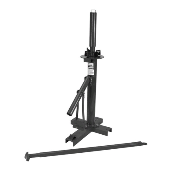
- Page 1 Large Manual Tire Changer Owner’s Manual WARNING: Read carefully and understand all ASSEMBLY AND OPERATION INSTRUCTIONS before operating. Failure to follow the safety rules and other basic safety precautions may result in serious personal injury. Item #54413 SAVE THESE INSTRUCTIONS...
- Page 2 Thank you very much for choosing a Strongway™ product! For future reference, please complete the owner’s record below: Serial Number/Lot Date Code: ________________________________ Purchase Date: ____________________________________________ Save the receipt, warranty, and this manual. It is important that you read the entire manual to become familiar with this product before you begin using it.
-
Page 3: Table Of Contents
Table of Contents Intended Use ............................4 Technical Specifications ........................4 Important Safety Information ....................... 4 Specific Operation Warnings ....................... 5 Assembly Instructions .......................... 6 Operating Instructions .......................... 8 Troubleshooting ..........................13 Parts Diagram ............................14 Parts List .............................. 14 Replacement Parts .......................... -
Page 4: Intended Use
Intended Use Strongway’s Large Manual Tire Changer allows you the freedom and ease of changing your own tires. Technical Specifications Property Specification Max. Rim Width (in.) Up to 16.5 Plate Diameter (in.) 11 13/16 Spindle Diameter (in.) 2 3/8 Base Dimensions (in.) 27 1/2 x 18 1/2 Dimensions L x W x H (in.) -
Page 5: Specific Operation Warnings
Do not use the tire changer where there is a risk of causing a fire or an explosion; e.g., in the presence of flammable liquids, gases, or dust. The product can create sparks, which may ignite the flammable liquids, gases, or dust. -
Page 6: Assembly Instructions
Wear ANSI Z871. Compliant safety goggles. Do not exceed the rated capacity. Use on a hard level surface. Use an adequate amount of lubricant while mounting and dismounting tire. Be sure that the bead is in the center of the rim during this process. ... - Page 7 3. Connect the casting pipe (#4) into the post (#3) with the lock pin (#5) and hair pin (#6). 4. Connect the shovel (#7) to the casting pipe (#4) with the lock pin (#5) and hair pin (#6). Page 7 of 17...
-
Page 8: Operating Instructions
5. Slip the slotted press plate (#8) into the top of the post (#3). 6. Rotate the threaded rod (#9) into the top of post (#3). Operating Instructions ⚠WARNING Release tire air pressure before using this tire changer. Wear ANSI Z871. - Page 9 Bead Breaking Before beginning, use a rubber lubricant (not included). It makes bead breaking, mounting, and demounting easier. 1. Place one piece of the pad on the base of the product. 2. To break the bead from the rim, lay the tire flat on the long leg base (#1). Page 9 of 17...
- Page 10 3. Insert the flat end of the mount /demount bar (#10) into the casting pipe (#4). Set the shovel (#7) on the tire against the edge of the rim. As you work with different sized tires you may need to adjust the shovel height.
- Page 11 2. Place the slotted press plate (#8) over the center post. 3. Screw the threaded rod (#9) onto the center post. Lock the slotted press plate into place by tightening by hand. Hand tightening should be enough but if you want a little more pressure, place the flat end of the dismount tool through the top of the threaded rod and use the extra leverage to tighten the threaded rod even more.
- Page 12 4. Once the tire is held securely in place, force demounting in between the tire and the rim. This should be done with the flat of the demount end against the rim. Pull the bar toward you across the tire to force the edge of the bead over the rim. 5.
-
Page 13: Troubleshooting
6. Pull the tire up toward the top bead, place the flat end of the demounting bar between the tire and the rim as before, and repeat. 7. To mount the tire back on the rim, with the other hand, pull the bar clockwise around the center post until the bead starts to mount onto the rim. -
Page 14: Parts Diagram
Parts Diagram Parts List Part Number Description Quantity Long Leg Short Leg Post Casting Pipe Lock Pin Hair Pin Arc Shovel Slotted Press Plate Threaded Rod Crowbar Bolt M10x25 Nut M10 Lock Washer 10 Flat Washer 10 Replacement Parts For replacement parts and technical questions, please call Customer Service at 1-800-222-5381. - Page 15 When ordering parts, the following information will be required: item description, item model number, item serial number/item lot date code, and the replacement part reference number. The distributor reserves the rights to make design changes and improvements to product lines and manuals without notice.
-
Page 16: Limited Warranty
Northern Tool and Equipment Company, Inc. ("We'' or "Us'') warrants to the original purchaser only ("You'' or “Your”) that the Strongway product purchased will be free from material defects in both materials and workmanship, normal wear and tear excepted, for a period of one year from date of purchase. - Page 17 Distributed by: Northern Tool & Equipment Company, Inc. Burnsville, Minnesota 55306 www.northerntool.com Made in China Page 17 of 17...