Table of Contents
Advertisement
Quick Links
Advertisement
Table of Contents
Troubleshooting

Related Manuals for Immergas NIKE MYTHOS 24 4 ERP


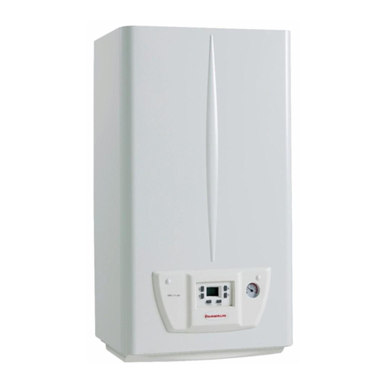
Summary of Contents for Immergas NIKE MYTHOS 24 4 ERP
- Page 1 NIKE MYTHOS Instruction and warning book 24 4 ERP...
- Page 2 Read the following pages carefully: you will be able to draw useful suggestions regarding the correct use of the appliance, the respect of which, will con rm your satisfaction for the Immergas product.
-
Page 3: Table Of Contents
INDEX INSTALLER page USER page MAINTENANCE TECHNICIAN page Instructions for use and maintenance ..11 Boiler installation ........4 Boiler commissioning (initial check) ...14 2.1 Cleaning and maintenance....11 1.1 Installation recommendations....4 3.1 Hydraulic diagram........14 2.2 Ventilation of the rooms......11 1.2 Main dimensions. -
Page 4: Boiler Installation
N.B.: the hex head screws supplied in the blister e NIKE MYTHOS 24 4 ERP boiler has been and contact an authorised company (e.g. the pack are to be used exclusively to x the relative... -
Page 5: Main Dimensions
MAIN DIMENSIONS. 1.3 CONNECTIONS OPTIONAL . Gas connection (Appliance category II 2H3+ Our boilers are designed to operate with methane gas (G20) or LPG. Supply pipes must be the same as or larger than the 3/4”G boiler tting. Before connecting the gas line, carefully clean inside all the fuel feed system pipes to remove any residue that could impair boiler e ciency. -
Page 6: Hydraulic Connection
1.5 ELECTRICAL CONNECTION. e chrono-thermostat is powered by two 1.5V e NIKE MYTHOS 24 4 ERP boiler has an LR 6 type alkaline batteries. IPX4D protection rating for the entire appliance. • Comando Amico Remoto Remote Control... -
Page 7: Ventilation Of The Rooms
1.7 VENTILATION OF THE ROOMS. FLUES/CHIMNEYS. 1.10 SYSTEM FILLING. In the room in which the boiler is installed it is For the appliances with natural draught Once the boiler is connected, proceed with necessary that at least as much air ows as that individual chimneys and branched flues can system filling via the filling valve (Fig. -
Page 8: Circulation Pump
1.13 CIRCULATION PUMP. e boiler is supplied with circulator tted with speed regulator. ese settings are suitable for most systems. In fact, the pump is equipped with electronic Key: control to set advanced functions. For proper op- 1 - Function selection button eration one must select the most suitable type of 2 - Green (G) / red (R) LED operation for the system and select a speed in the... -
Page 9: Kits Available On Request
Total head available to the system. Closed bypass Key: V2 = Total head available to the system with pump at speed 2 V3 = Total head available to the system with pump at speed 3 V4 = Total head available to the system with pump at speed 4 A2 = Power absorbed by the pump at speed 2 A3 = Power absorbed by the pump at speed 3... -
Page 10: Boiler Components
1.15 BOILER COMPONENTS. Key: 11 - Combustion chamber 1 - Fumes hood 12 - Ignition and detection electrodes 2 - System pressure switch 13 - System expansion vessel 3 - Boiler circulator pump 14 - Burner 4 - Domestic hot water ow switch 15 - Vent valve 5 - Gas valve 16 - By-pass... -
Page 11: Instructions For Use And Maintenance
INSTRUCTIONS FOR USE In the case of work or maintenance to structures - if the appliance is not to be used for a certain located in the vicinity of ducting or devices period, disconnect the main power switch. AND MAINTENANCE for flue extraction and relative accessories, 2.1 CLEANING AND MAINTENANCE. -
Page 12: Troubleshooting
When the winter position is selected ( ) the in the lower part of the boiler (Fig. 2-2). technician for assistance (e.g. Immergas A er- system water temperature is adjusted with the Sales Service). N.B.: close the lling cock a er the operation. -
Page 13: Anti-Freeze Protection
2.8 ANTI FREEZE PROTECTION. e boiler features an antifreeze function that automatically ignites the burner when the tem- perature falls below 4°C and stops once 42°C have been exceeded. e antifreeze function is ensured if the appliance is in perfect working order in all its parts, if it is not “blocked”, and if it is not in “o ”... -
Page 14: Boiler Commissioning Initial Check
BOILER COMMISSIONING - make sure the gas maximum, intermediate - ensure activation of all adjustment devices; and minimum ow rate and pressure values INITIAL CHECK - seal the gas ow rate regulation devices (if correspond to those given in the handbook settings are modi ed);... -
Page 15: Wiring Diagram
In this case, make the boiler run at higher temperatures. N.B.: maintenance interventions must be carried - Frequent interventions of the flue safety out by an authorised company (e.g. Immergas A er-Sales Technical Assistance Service). thermostat. is can be caused by obstructions in the fumes circuit. -
Page 16: Converting The Boiler To Other Types Of Gas
- Open the domestic hot water cock in order to out by an authorised company (e.g. Immergas N.B.: a er a period of time, without touching prevent modulation intervention. A er-Sales Technical Assistance Service). -
Page 17: Automatic Slow Ignition Function With Timed Ramp Delivery
3.9 "CHIMNEY SWEEP FUNCTION". SIT 845 GAS Valve When activated, this function forces the boiler at max. output for 15 minutes. In this state all adjustments are excluded and Key: only the temperature safety thermostat and the 1 - Coil limit thermostat remain active. -
Page 18: Casing Removal
3.14 CASING REMOVAL. - undo the 2 front screws (2) and the 2 lower To facilitate boiler maintenance the casing can be screws (3) which fasten the casing (4); completely removed as follows (Fig. 3-4): - pull the casing (4) towards yourself and - remove the frame (1) holding the edges and upwards at the same time in order to detach it pulling it towards you as indicated by the... -
Page 19: Yearly Appliance Check And Maintenance
3.15 YEARLY APPLIANCE CHECK AND - Check that, a er discharging system pressure MAINTENANCE. and bringing it to zero (read on boiler pressure e following checks and maintenance should gauge), the expansion vessel load is at 1.0 bar. be performed at least once a year. - Check that the system static pressure (with - Clean the ue side of the heat exchanger. -
Page 20: Combustion Parameters
3.17 COMBUSTION PARAMETERS. Gas nozzle diameter 1.30 0.80 0.80 supply pressure mbar (mm H 20 (204) 29 (296) 37 (377) Flue ow rate at nominal heat output kg/h Flue ow rate at min heat output kg/h at Nom./Min. Q. 5.20 / 1.80 6.20 / 2.34 6.00 / 2.21 CO with 0% O... -
Page 21: Data Plate Key
3.19 DATA PLATE KEY. Cod. Md Sr N° Cod. PIN Type n min. max. n min. n max. Class Note: the technical data are shown on the boiler data plate Model Cod. Md Model code Sr N° Serial Number Check Cod. -
Page 22: Technical Parameters For Combination Boilers In Compliance With Regulation 813/2013
Contact information IMMERGAS S.p.A. VIA CISA LIGURE, 95 - 42041 BRESCELLO (RE) ITALY (*) High temperature mode means 60°C on return and 80°C on ow. (**) Low temperature mode for condensation Boilers means 30°C , for low temperature boilers 37°C and for other appliances 50°C of return tempera- ture. -
Page 23: Che
In case you should wish to install an assembly, to make up the assembly (e.g. solar devices, starting from the NIKE MYTHOS 24 4 ERP boil- integration heat pumps, temperature controllers). er, use the assembly charts in Fig. 3-7 and 3-10. - Page 24 Parameters for lling in the assembly chart. Parameter NIKE MYTHOS 24 4 ERP ‘I’ ‘II’ ‘III’ 1,11 ‘IV’ 0,44 * to be established by means of table 5 of Regulation 811/2013 in case of “assembly” including a heat pump to integrate the boiler. In this case the boiler must be considered as the main appliance of the assembly.
- Page 25 Facsimile for lling in domestic hot water production system package che.
- Page 26 Parameters for lling in DHW package assembly chart. Parameter NIKE MYTHOS 24 4 ERP ‘I’ ‘II’ ‘III’ * to be determined according to Regulation 811/2013 and transient calculation methods as per Notice of the European Community no. 207/2014. Domestic hot water production system package che.
- Page 28 Follow us Immergas Italia immergas.com Immergas S.p.A. 42041 Brescello (RE) - Italy Tel. 0522.689011 Fax 0522.680617 Certi ed company ISO 9001...