
Related Manuals for Vaisala HUMICAP HMT130


Summary of Contents for Vaisala HUMICAP HMT130
- Page 1 M211280EN-D User Guide â Vaisala HUMICAP Humidity and Temperature Transmitter Series HMT130...
- Page 2 English versions are This product contains software developed applicable, not the translations. by Vaisala or third parties. Use of the The contents of this document are subject software is governed by license terms and to change without prior notice.
-
Page 3: Table Of Contents
Table of contents Table of contents About this document..................7 Version information..................7 Related manuals....................7 Documentation conventions................8 Trademarks......................8 Product overview.................... 9 Introduction to HMT130................... 9 Accessories......................9 Fixed and remote probe models..............10 Optional display....................10 Interchangeable probe................... 10 Constant output probe.................. - Page 4 HMT130 User Guide M211280EN-D Maintenance....................55 Removing and fastening fixed probe............55 Removing and fastening remote probe............56 Testing analog outputs.................. 56 Replacing the HUMICAPâ sensor..............57 Calibration and adjustment..............58 Calibration and adjustment overview ............58 Push-button calibration.................59 6.2.1 Adjusting humidity and temperature with push buttons....59 Adjusting RH and T with MI70 handheld indicator........
- Page 5 Table of contents Recycling......................85...
- Page 6 HMT130 User Guide M211280EN-D List of figures Figure 1 Main transmitter parts..................12 Figure 2 Opening the transmitter cover..............14 Figure 3 Wall mounting measurements..............15 Figure 4 Installation with rain shield................16 Figure 5 Probe Installation with radiation shield............17 Figure 6 Probe installation with the duct installation kit........18 Figure 7...
- Page 7 List of tables List of tables Table Document versions (English)................7 Table 2 Related manuals....................7 Table 3 Wiring Table......................23 Table 4 Default serial interface settings..............25 Table 5 List of serial commands.................. 28 Table 6 ? command......................30 Table 7 CALCS command....................30 Table 8 CDATE command....................
- Page 8 HMT130 User Guide M211280EN-D Table 46 SDELAY command....................52 Table 47 INTV command....................53 Table 48 ADDR command....................53 Table 49 SEND command....................53 Table 50 OPEN command....................54 Table 51 CLOSE command....................54 Table 52 Error codes, descriptions, and texts............67 Table 53 Problems and solutions...................68 Table 54 HMT130 measurement performance............
-
Page 9: About This Document
1.2 Related manuals Table 2 Related manuals Document code Description M210185EN Vaisala Humidity Calibrator HMK15 User Guide M210297EN Vaisala Handheld Humidity and Temperature Meter HM70 User Guide M211060EN Vaisala Humidity and Temperature Probes HMP60 and HMP110 Series User Guide... -
Page 10: Documentation Conventions
Indicates that you need to take some notes during the task. 1.4 Trademarks Vaisalaâ and HUMICAPâ are registered trademarks of Vaisala Oyj. All other product or company names that may be mentioned in this publication are trade names, trademarks, or registered trademarks of their respective owners. -
Page 11: Product Overview
0 … 10 V range. HMT130 has also an RS-485 digital interface and a relay. The HMP110 series measurement probes used with HMT130 incorporate the reliable Vaisala HUMICAPâ humidity sensor technology. The HMT130 transmitter's output parameters are configurable. Available parameters for outputs are limited to two at a time. -
Page 12: Fixed And Remote Probe Models
Vaisala: • Order a new probe and keep your current one. • Order a new probe and return the old one to Vaisala (replacement probe). Only probes that have a compatible digital output (VDIGI mode) can be used with the transmitter. -
Page 13: Constant Output Probe
Chapter 2 – Product overview 2.6 Constant output probe The constant output probe HMP110REF is a testing accessory that can be used to check the transmitter's functions and measurement signal transfer chain all the way to the control system. The constant output probe does not measure humidity and temperature; instead, it outputs constant humidity and temperature readings. -
Page 14: Safety
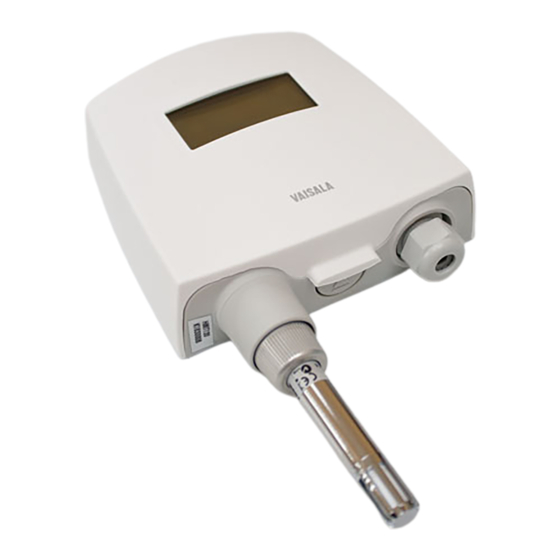
HMT130 User Guide M211280EN-D Figure 1 Main transmitter parts Transmitter enclosure Probe cable Probe Plastic grid filter Cable bushing: cable gland, cable grommet, or conduit fitting More information ‣ Spare parts and accessories (page 73) 2.8 Safety The transmitter delivered to you has been tested for safety and approved as shipped from the factory. -
Page 15: Esd Protection
2.8.1 ESD Protection Electrostatic Discharge (ESD) can cause immediate or latent damage to electronic circuits. Vaisala products are adequately protected against ESD for their intended use. It is possible to damage the product, however, by delivering electrostatic discharges when touching, removing, or inserting any objects inside the equipment housing. -
Page 16: Installation
HMT130 User Guide M211280EN-D 3. Installation 3.1 Opening the transmitter cover Figure 2 Opening the transmitter cover To open the transmitter cover: 1. If the transmitter is not mounted already, hold it against a flat surface. 2. Push on the cover with your thumb, and pull the bottom part of the cover towards yourself. -
Page 17: Figure 3 Wall Mounting Measurements
Chapter 3 – Installation 1. Remove the transmitter cover. 2. Make sure that the transmitter is correctly aligned and attach it directly to the wall with up to four screws (not included in the package). Figure 3 (page 15) shows the distances between attachment points. -
Page 18: Installation With Rain Shield
HMT130 User Guide M211280EN-D 3.3 Installation with rain shield The installation kit with rain shield (Vaisala item code 215109) includes a metal mounting plate and a rain shield for the transmitter. Figure 4 Installation with rain shield To install the transmitter with the rain shield: 1. -
Page 19: Installation With Radiation Shield
Chapter 3 – Installation 3.4 Installation with radiation shield DTR504 with probe installation kit (Vaisala item code DTR504A) includes the rain/ solar radiation shield DTR504 and a plastic installation support for the humidity probe. If you already have the DTR504 shield and... -
Page 20: Duct Installation Kit
M211280EN-D 3.5 Duct installation kit The duct installation kit includes a plastic pipe with a flange (Vaisala item code 215619). To install the probe with the duct installation kit, drill a hole in the duct wall, assemble the probe to the duct installation kit, slide the probe head through the hole, and attach the flange to the duct wall with four screws. -
Page 21: Probe Assembly With Duct Installation Kit
Chapter 3 – Installation 3.5.1 Probe assembly with duct installation kit Figure 7 Probe assembly with duct installation kit Probe Duct installation kit Probe cable 1. Slide the probe cable through the plastic pipe in the duct installation kit. 2. Attach the probe cable to the probe. 3. -
Page 22: Drilling Instructions For Duct Installation Kit
The optional mounting clamp makes it easy to install the probe on the wall of the measurement environment. The probe can be detached for calibration simply by loosening the lower screw. You can order a single clamp (Vaisala order code 225501) or a set of 10 clamps (226067). -
Page 23: Probe Mounting Flange
3.7 Probe mounting flange The probe mounting flange (Vaisala item code 226061) is a general purpose mounting flange for 12 mm (0.47 in) diameter probes. It can be used to hold the probe in a through-wall installation. -
Page 24: Connections
HMT130 User Guide M211280EN-D 3.8 Connections Figure 11 (page 22) shows the main parts of the HMT130 component board, including the wiring connectors. 485 TERM 485- SERVICE PORT 485+ Figure 11 HMT130 component board Optional LCD display Indicator LEDs Adjustment buttons Service port RS-485 bus termination switch Relay terminals RS-485 bus... -
Page 25: Wiring
Chapter 3 – Installation 3.8.1 Wiring 485- 485+ 10 ... 35 V DC 24 V AC Figure 12 Power supply and voltage outputs (A), and serial communication and relay (B) 15 … 35 V DC or 24 V AC is needed when using the 0 … 10 V output. Table 3 Wiring Table Description Terminal... -
Page 26: Rs-485 Bus Termination
HMT130 User Guide M211280EN-D Description Terminal Relay Numbers 1 … 6 in the first column of the wiring table refer to section (A) and numbers 7 … 11 to section (B) in Figure 12 (page 23). There is an internal connection between numbers 1 and 5 on section (A) and number 9 on section (B). -
Page 27: Serial Line Operation
4.1 Using the service port The transmitter's component board has an 8-pin RJ-45 connector for service use. The service port uses RS-232 signaling levels. Vaisala offers an optional USB cable (Vaisala item code 219685) for connecting the transmitter to your computer. -
Page 28: Connecting With A Computer
3. Locate the cable in the list of devices: • If the device is listed as Vaisala USB Device with a COM port number in brackets, the cable is ready for use. Note the COM port number, you will need it later. - Page 29 The steps below describe how to connect to the transmitter using the PuTTY terminal application for Windows and a USB computer connection cable. 1. If you have not used the Vaisala USB cable before, install the driver before attempting to use the cable.
-
Page 30: List Of Serial Commands
HMT130 User Guide M211280EN-D 7. To open the connection window and start using the serial line, select Open. If PuTTY is unable to open the serial port you selected, it shows you an error message instead. If this happens, restart PuTTY and check the settings. 4.5 List of serial commands All commands can be issued either in uppercase or lowercase. - Page 31 Chapter 4 – Serial line operation Command Description CTCLR Restore probe T factory calibration CTEXT Set/show calibration info DSEL Set/show displayed parameters ECHO Set/show terminal echo mode Set/show environmental parameters ERRS Display active errors FORM Set/show output formatting FRESTORE Restore all transmitter settings to factory defaults HELP List available commands INTV...
-
Page 32: Device Information And Status
HMT130 User Guide M211280EN-D 4.6 Device information and status Table 6 ? command Syntax Description ?<cr> Show listing of device information. ??<cr> Show listing of device information even if device is in poll mode and connection has not been opened using the open command. -
Page 33: Table 8 Cdate Command
Chapter 4 – Serial line operation Syntax Description Examples: >calcs RH Td > calcs td t > The TMT130 temperature transmitter model has only one measurement parameter, T. Measurement parameters are referred to as 'quantities' in the transmitter's software. Table 8 CDATE command Syntax Description cdate<cr>... -
Page 34: Table 9 Ctext Command
[text]<cr> Set a new calibration information text to be shown after the automatic text "Calib. info". Example: ctext Calib. info: "VAISALA HELSINKI" > Example (set a new information text): ctext Calibration lab 2 Calib. info: "Calibration lab 2" >... -
Page 35: Table 11 System Command
Chapter 4 – Serial line operation Syntax Description Example (no active errors): >aout *** ANALOG OUTPUT 1 *** Ch1 Analog out mode : 0_10V Ch1 Error level : 10.8 Ch1 Quantity : RH Ch1 Status : ON RH lo RH hi : 100 : 36.64 % Ch1 Voltage... -
Page 36: Serial Line Output And Communication
HMT130 User Guide M211280EN-D 4.7 Serial line output and communication Table 13 R command Syntax Description r<cr> Use the r command to start the continuous outputting of measurement values as an ASCII text string to the serial line. The output always includes the readings of the currently selected analog output parameters. -
Page 37: Calibration Commands
Chapter 4 – Serial line operation Syntax Description intv [iii uuu]<cr> Set the output interval. iii = interval, range 0 ... 255. u = unit for interval setting: • s = seconds • min = minutes • h = hours If you set the interval to 0, the output messages are output as quickly as they are generated, without additional delay. -
Page 38: Table 17 Crh Command
HMT130 User Guide M211280EN-D Table 17 CRH command Syntax Description crh<cr> Use the crh command to perform a 1-point or 2-point humidity (RH) calibration. When performing a 1-point calibration, you need to place the probe in a single humidity reference with RH < 50%. Run the command and enter the exact RH of the reference after the measurement has stabilized. -
Page 39: Table 19 Ct Command
Chapter 4 – Serial line operation Syntax Description Example: >crhclr > Table 19 CT command Syntax Description ct<cr> Use the ct command to perform a 1-point or 2-point temperature calibration. When performing a 1-point calibration, you need to place the probe in a single temperature reference. Run the command and enter the exact temperature of the reference after the measurement has stabilized. -
Page 40: Table 20 Ctclr Command
HMT130 User Guide M211280EN-D Table 20 CTCLR command Syntax Description ctclr<cr> Use the ctclr command to restore the probe temperature factory calibration. Example: >ctclr > Table 21 ACAL command Syntax Description acal<cr> Use the acal command to calibrate the analog current loop outputs. -
Page 41: Configuring Serial Line Operation
Chapter 4 – Serial line operation 4.9 Configuring serial line operation Table 22 SERI command Syntax Description seri [b p d s]<cr> Use the seri command to show or set the serial line settings for the serial port that you are currently using. Use where the SAVE command after changing the settings to store baud rate (9600, 19200, 38400,... -
Page 42: Measurement Parameter Configuration Commands
HMT130 User Guide M211280EN-D Table 24 SMODE command Syntax Description smode [stop/run]<cr> Use the smode command to show or set the serial interface mode. Note that a separate save command is not needed to store the new serial interface mode setting. STOP outputting only when command is issued, mode... -
Page 43: Analog Output Configuration Commands
Pressure (bar) : 0.98 >save Saving settings...done > You can use the Vaisala Humidity Calculator to simulate the effect of pressure change to dew point. The Humidity Calculator is available at: www.vaisala.com/humiditycalculator 4.11 Analog output configuration commands Table 26 AMODE command Syntax... -
Page 44: Table 27 Aerr Command
HMT130 User Guide M211280EN-D Syntax Description Example: User prompted to accept currently used channel limits or enter new limits >amode x_yv Ch1 Analog out mode : X_YV Ch2 Analog out mode : 0_10V ? Ch1 low limit : 0 ? Ch1 high limit : 10 ? 1 >... - Page 45 Chapter 4 – Serial line operation Syntax Description Examples: >asel Ch1 Quantity : RH RH lo RH hi : 100 Ch2 Quantity T lo : -60 T hi : 100 > >asel rh td Ch1 Quantity : RH RH lo RH hi : 100 Ch2 Quantity...
-
Page 46: Relay Output Configuration
HMT130 User Guide M211280EN-D Table 29 ATEST command Syntax Description atest [val1 val2]<cr> Use the atest command to test the analog outputs. The atest command will force the where output to the given value, which can then be val1 val2 Analog channel output value (V) measured with a calibrated multimeter. -
Page 47: Table 31 Rmode Command
Chapter 4 – Serial line operation Table 31 RMODE command Syntax Description rmode [xxxx] [lo] [hi]<cr> Use the rmode command to set/show relay mode, low and high limits. Relay modes are OFF, where LO_OPEN and HI_OPEN. Low and high values xxxx OFF, LO_OPEN or HI_OPEN specify relay operation limits for the selected Low limit... -
Page 48: Other Commands
HMT130 User Guide M211280EN-D 4.13 Other commands Table 33 DSEL command Syntax Description dsel [q1 q2]<cr> After you have defined the measurement parameters with the calcs command, use the where dsel command to show or set the displayed q1 q2 Measurement parameters to be shown parameters. -
Page 49: Table 34 Form Command
Chapter 4 – Serial line operation Table 34 FORM command Syntax Description form <format><cr> After you have defined the measurement parameters with the calcs command, use the where format is a formatting string that form command to set the output format for the consists of one of the following fields: send and r commands. -
Page 50: Table 35 Help Command
HMT130 User Guide M211280EN-D Syntax Description Examples: >form "RH= " 3.2 U2 rh #r #n >send RH= 32.16 % > >form "t=" 4.1 U3 t \t "rh=" 3.2 U2 rh \r \n >send 22.5 'C rh= 29.12 % > >form "t=" 4.1 U3 t \t "rh=" rh \r \n >send 22.3 'C 29.5%... -
Page 51: Table 37 Save Command
Chapter 4 – Serial line operation Syntax Description Example (no active errors): >errs No errors. > Table 37 SAVE command Syntax Description save<cr> Use the save command to save changed settings to the transmitter FLASH memory. Most settings have to be saved or the changes are lost at the next reset or power down. -
Page 52: Table 39 Reset Command
HMT130 User Guide M211280EN-D Table 39 RESET command Syntax Description reset<cr> Use the reset command to reset the transmitter. Upon reset or power-up, the transmitter enters the serial mode that has been set with the smode command. After a reset, the configuration is loaded from FLASH memory. -
Page 53: User Port (Rs-485) Commands
Chapter 4 – Serial line operation Syntax Description Examples: >unit Unit : METRIC > >unit non_metric Unit : NON_METRIC > 4.14 User port (RS-485) commands The RS-485 interface enables communication between RS-485 network and HMT130 transmitter. The RS-485 interface is not isolated. Set the RS-485 interface by using the commands listed in this section. -
Page 54: Table 44 Echo Command
HMT130 User Guide M211280EN-D Table 44 ECHO command Syntax Description echo [x]<cr> Use the echo command to enable/disable echo of characters received over the serial line. where ON or OFF (default=OFF) When using a 2-wire connection, echo must be always disabled (OFF). -
Page 55: Table 47 Intv Command
Chapter 4 – Serial line operation Table 47 INTV command Syntax Description intv [n xxx]<cr> Use the intv command to set the RUN mode output interval. where 1 ... 255 The time interval is used only when the RUN S, MIN or H mode is active. -
Page 56: Table 50 Open Command
HMT130 User Guide M211280EN-D Table 50 OPEN command Syntax Description open [aa]<cr> When all transmitters on the RS-485 bus are in POLL mode, the open command sets one where transmitter temporarily to STOP mode so that address of the transmitter (set with the other commands can be entered. -
Page 57: Maintenance
Chapter 5 – Maintenance 5. Maintenance 5.1 Removing and fastening fixed probe To remove or replace the probe: 1. Loosen the metal locking bushing by carefully turning it counterclockwise. 2. Remove the probe from the transmitter by pulling it gently downwards. 3. Attach the new probe to the 4-pin M8 panel connector at the transmitter (only one position possible). -
Page 58: Removing And Fastening Remote Probe
HMT130 User Guide M211280EN-D 5.2 Removing and fastening remote probe To remove or replace the probe: 1. Unscrew the small sleeve that secures the probe in place at the end of the probe cable and pull out the probe. 2. Replace the probe and screw the small sleeve back on, securing the probe tightly in place. Figure 14 Removing the probe (remote probe model) Probe cable Sleeve securing the probe to the cable... -
Page 59: Replacing The Humicapâ Sensor
Chapter 5 – Maintenance 3. Press the - adjustment button. This sets the output voltage level to the low point of the analog output range (for example 0 V). The output stays at this level for about 30 seconds after the - adjustment button has been pressed. 10 ... -
Page 60: Calibration And Adjustment
In case the probe is outside its adjustment/trim range due to, for example, chemical exposure, the calibration cannot be completed. In this case, it is recommended that you change the probe or contact Vaisala technical support. More information ‣... -
Page 61: Push-Button Calibration
Chapter 6 – Calibration and adjustment 6.2 Push-button calibration 485 TERM 485- SERVICE PORT 485+ Figure 16 Adjustment buttons You can calibrate and adjust the transmitter with the adjustment buttons on the transmitter component board. The 2-point humidity adjustment is carried out by using two relative humidity references: for example saturated salt points 11 %RH (LiCl) and 75 %RH (NaCl). - Page 62 HMT130 User Guide M211280EN-D 3. The transmitter is now in RH calibration state. Analog output and optional display will still follow the actual measured RH value. If you do not wish to perform the RH adjustment at this time, press the ADJ button one more time.
- Page 63 Chapter 6 – Calibration and adjustment 8. Insert the probe into a known reference temperature (if Vaisala Humidity Calibrator HMK15 is not used) and let the temperature reading stabilize. Do not touch the adjustment buttons before the conditions have stabilized.
-
Page 64: Adjusting Rh And T With Mi70 Handheld Indicator
• MI70 handheld indicator (included in, for example, the HM70 package) • MI70 connection cable (Vaisala item code 211339) You can check and adjust the transmitter's relative humidity and temperature measurement with the MI70 handheld indicator, which is included in the HM70 handheld humidity and temperature meter. -
Page 65: Field Checking And Adjustment Using A Calibrated Reference Probe
Chapter 6 – Calibration and adjustment 5. Press the ADJ button on the transmitter's component board to open the adjustment mode. Both LEDs on the component board remain in OFF state and the text Starting adjustment mode for HMP110 is shown on the MI70 display. In transmitters with the optional display, the text MI70 adjustment mode is shown on the upper row of the display. -
Page 66: 1-Point Adjustment Using A Calibrator
HMT130 User Guide M211280EN-D 6.3.2 1-point adjustment using a calibrator Complete the steps listed in Adjusting RH and T with MI70 handheld indicator (page 62) before continuing with this adjustment option. 1. Remove the filter from the transmitter's probe and insert the probe head into the reference condition. -
Page 67: Licl-Nacl Adjustment
Chapter 6 – Calibration and adjustment 3. Choose 2-point adjustment from the MI70 adjustment menu and press SELECT. 4. Press READY when the reading has stabilized in the first reference condition (can take 30 minutes or more). You can follow the stabilization from the GRAPH display. 5. -
Page 68: Temperature Field Check And Adjustment Using A Calibrated Reference Probe
HMT130 User Guide M211280EN-D 6.3.5 Temperature field check and adjustment using a calibrated reference probe Complete the steps listed in Adjusting RH and T with MI70 handheld indicator (page 62) before continuing with this adjustment option. 1. Check that the probes are located in equal conditions and wait until the readings have stabilized (can take 30 minutes or more). -
Page 69: Troubleshooting
Chapter 7 – Troubleshooting 7. Troubleshooting 7.1 Error codes The transmitter's software provides a variety of self diagnostics information, for example, FLASH and program memory checksum, probe communication status, probe checksum, operation voltage check, and oscillator fault check. At startup, the transmitter's software checks the factory/user settings checksum, program memory checksum, and oscillator fault status. -
Page 70: Solving Typical Problems
2. Return the module to factory settings with the frestore serial line command. Check again. 3. If the error is still active, contact a Vaisala service center. Any of the following errors is active: Faulty transmitter, contact a Vaisala service •... -
Page 71: Analog Output Error Notification
Chapter 7 – Troubleshooting Problem or message Likely causes and solutions Any of the following errors is active: • In case of Analog output quantity invalid error, select the correct output quantities (set • Analog output quantity invalid with the calcs command) with the asel •... -
Page 72: Technical Data
HMT130 User Guide M211280EN-D 8. Technical data 8.1 Specifications Table 54 HMT130 measurement performance Property Description/Value Relative humidity Measurement range 0 … 100 %RH 2) 3) Accuracy At 0 … +40 °C (+32 … +104 °F) ±1.5 %RH (0 … 90 %RH) ±2.5 %RH (90 … 100 %RH) With HMP110 probe: At −40 …... -
Page 73: Table 55 Hmt130 Operating Environment
Chapter 8 – Technical data Property Description/Value HMP113: At 0… +40 °C (+32 … +104 °F) ±0.2 °C (±0.36 °F) At −40 … 0 °C and +40 … +60 °C ±0.4 °C (±0.72 °F) (−40 … +32 °F and +104 … +140 °F) Other output parameters (optional) Dew point/frost point, wet bulb temperature, enthalpy, absolute humidity, mixing ratio, vapor pressure, saturation vapor pressure... -
Page 74: Table 57 Hmt130 Mechanical Specifications
HMT130 User Guide M211280EN-D Property Description/Value Supply voltage 10 … 35 V DC 15 … 35 V DC (when output 0 … 10 V) 24 V AC (±20 %) Current consumption at 24 V DC 8 mA, if relay closed 15 mA Max. -
Page 75: Spare Parts And Accessories
Chapter 8 – Technical data 8.2 Spare parts and accessories Table 58 HMT130 spare parts and accessories Description Item code Probes Humidity and temperature probe HMP110 Humidity and temperature replacement probe HMP110R Temperature-only probe HMP110T Constant output probe HMP110REF Humidity and temperature probe HMP113 Sensors Standard humidity sensor... -
Page 76: Transmitter Dimensions
HMT130 User Guide M211280EN-D Description Item code Probe cable 5 m (16 ft) HMT120Z500 Probe cable 10 m (33 ft) HMT120Z1000 Probe cable 20 m (66 ft) HMT120Z2000 HM70 connection cable 211339 USB serial interface cable 219685 Transmitter protection and installation Radiation shield DTR504A Rain shield with installation kit... -
Page 77: Figure 18 Remote Probe Model Dimensions In Mm [In]
Chapter 8 – Technical data 120 [4.72] 37 [1.46] Ø12 [0.47] [in] Figure 18 Remote probe model dimensions in mm [in]... -
Page 78: Appendix A: Calculation Formulas
HMT130 User Guide M211280EN-D Appendix A. Calculation formulas A.1 Calculation formulas overview The transmitter receives the relative humidity and temperature values from the HMP110 probe. Based on these temperature and relative humidity values, the transmitter calculates dew point, frost point, absolute humidity, mixing ratio, enthalpy, wet bulb temperature, saturation vapor pressure and vapor pressure in normal pressure. -
Page 79: Dew/Frost Point Temperature Calculation
Appendix A – Calculation formulas 100 ... 150 °C 5.8493 7.2756 225.00 150 ... °C 6.2301 7.3033 230.00 A.3 Dew/frost point temperature calculation Dew/frost point temperature (T ) is calculated with the following formula: T d ≥ 0 T df = T d T d <... -
Page 80: Water Vapor Pressure Calculation
HMT130 User Guide M211280EN-D Water vapor saturation pressure (P ) is calculated with the following 2 formulas: ∑ C i T i Θ = T − ℎPa i = 0 where Temperature in K Coefficients 0.49313580 -0.46094296 * 10 0.13746454 * 10 -0.12743214 * 10 ∑... -
Page 81: Enthalpy Calculation
Appendix A – Calculation formulas where 216.679 gK/J A.8 Enthalpy calculation Enthalpy (h) can be calculated from the mixing ratio (x) using the following formula: ℎ = T ⋅ 1.01 + 0.00189 ⋅ x + 2.5 ⋅ x kJ/kg A.9 Accuracies of calculated variables Accuracies of the calculated variables depend on the calibration accuracy of the humidity and temperature sensors;... -
Page 82: Accuracy Of Mixing Ratio G/Kg (Ambient Pressure 1013 Mbar)
HMT130 User Guide M211280EN-D A.9.2 Accuracy of mixing ratio g/kg (ambient pressure 1013 mbar) Table 62 Accuracy of mixing ratio g/kg (ambient pressure 1013 mbar) Relative humidity (%RH) Temp -40 °C 0.003 0.003 0.003 0.003 0.003 0.004 0.004 0.004 — — -20 °C 0.017 0.018 0.019... -
Page 83: Accuracy Of Absolute Humidity G/M
Appendix A – Calculation formulas A.9.4 Accuracy of absolute humidity g/m Table 64 Accuracy of absolute humidity g/m Relative humidity (%RH) Temp -40 °C 0.004 0.004 0.005 0.005 0.005 0.006 0.006 0.006 -20 °C 0.023 0.025 0.027 0.029 0.031 0.032 0.034 0.036 0 °C 0.10 0.11... -
Page 85: Index
Index Index HMT130 overview............. 9 absolute humidity calculation......78 accessories..............9 accuracies of calculated variables.....79 indexterm..............56 accuracy of absolute humidity g/m3....81 installing with radiation shield......17 accuracy of dew point temperature °C....79 installing with rain shield........16 accuracy of mixing ratio g/kg (ambient interchangeable probe..........10 pressure 1013 mbar)..........80 introduction............... - Page 86 HMT130 User Guide M211280EN-D relay output configuration........44 removing and fastening fixed probe....55 removing and fastening remote probe....56 replacing the HUMICAP sensor......57 RS-485 bus termination........24 safety..............12, 13 saturation vapor pressure calculation....77 serial interface settings........25 serial line operation commands......39 serial line output and communication commands.............
-
Page 87: Warranty
Please see the applicable supply contract or Conditions of Sale for details of the warranty for each product. Technical support Contact Vaisala technical support at helpdesk@vaisala.com. Provide at least the following supporting information as applicable: • Product name, model, and serial number •... - Page 90 www. v aisala.com...