Advertisement
Quick Links
Advertisement

Related Manuals for Drive Ultra Light Plus


Summary of Contents for Drive Ultra Light Plus
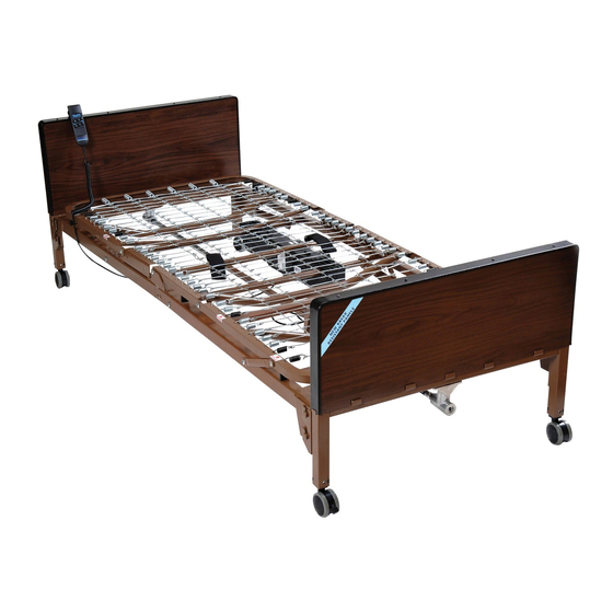
- Page 1 Competitor Ultra Light Plus, Semi Electric Bed Item # 15560 Owner’s Assembly And Operating Manual...
- Page 2 Assembly Instructions 1. Remove contents from carton. 2. Place both ends of the sleep surface on their side and align the flange with the receptacle as shown. 3. To attach the head and foot spring, pull the black knob away for the frame and slide the two sides together. The lock knob is spring loaded and will lock into position when released and the two sections of the bed are flush together. To disassemble the head and foot section, pull the black lock knob out and rotate the knob a quarter turn. The lock knob will remain open to allow the head section to be removed from the foot section.
- Page 3 Assembly Instructions Cont. 4. Secure the sleep surface with the cotter pin as shown. 5. Lock the cotter pin with the attached clasp. Repeat on the opposite side.
- Page 4 Assembly Instructions Cont. 6. Lay the sleep surface flat on the ground. NOTE: Before installing motor, plug hand pendant cable into motor as shown...
- Page 5 Assembly Instructions Cont. 7. Connect the 9V battery (sold separately) to the battery clip on the motor. It is stored in the recess under the motor cover. With this battery installed, the motor can be operated to return the sleep surface to the horizontal position in the event of a power failure. 8. To install motor, remove locking caps on top of the motor.
- Page 6 Assembly Instructions Cont. There are two methods for the installation of the motor Method A The motor is installed on the bed frame when the frame is standing on its side. Installation instructions can be found on pages 8-9. Method B The motor is installed from underneath the bed frame (horizontal to the ground) Installation instructions can be found on pages 10-11.
- Page 7 Assembly Instructions Cont. Method A Installation of the motor when bed frame is on its side A1. Prior to installation, make sure that the 2 white motor blocks are in the retracted position. CORRECT INCORRECT A2. Align the opening on the head end of the Actuator Bar motor with the flange on the head section of the bed and insert the flange into the motor compartment. A3. With the palm of your hand, snap the motor flush to the actuator bar. A4. Align the opening on the foot end of the motor with the flange on the foot section of the bed and insert the flange into the motor compartment.
- Page 8 Assembly Instructions Cont. A5. Once in place, replace the motor covers to secure the motor. A6. Be sure the sleep surface is locked securely to the head/foot board by as shown.
- Page 9 Assembly Instructions Cont. A7. Repeat for the other side. End Method A...
- Page 10 Assembly Instructions Cont. Method B Installation of the motor from underneath the frame B1. Be sure the sleep surface is locked securely to the head/foot board by as shown. B2. Repeat for the other side.
- Page 11 Assembly Instructions Cont. B3. Prior to installation, make sure that the 2 white motor blocks are in the retracted position. CORRECT INCORRECT B4. Remove the covers from the motor and place under the bed and aligned with the actuator under the head section. There are labels on the motor that provide direction and placement in relation to the head section. B5. With both hands, lift the motor and insert into the actuator and frame as shown.
- Page 12 Assembly Instructions Cont. B6. Once in place, replace the motor covers to secure the motor. End Method B...
- Page 13 Assembly Instructions Cont. 9. To install bed rails, lift the head section and find the rail receptacle located on the frame of the bed as shown. 10. Pull receptacle outward and return head section to the flat position. 11. Turn the receptacle in order to receive the rail. Repeat for all four rail receptacles.
- Page 14 Assembly Instructions Cont. 12. Insert the bed rail into the receptacle. Repeat for the other rail. 13. The Competitor bed has two height adjustments. 13A. Adjustment one is located on the frame as indicated below. There is a high position and a low position.
- Page 15 Assembly Instructions Cont. 13B. Adjustment two is on the leg of the head and foot board. To adjust, loosen the thumb screw on the leg and pull on the spring loaded knob with one hand and slide the leg to the desired height with the other hand. Once the desired position is found, turn the thumb screw until tight. Adjust other legs to the same position.
- Page 16 Assembly Instructions Cont. The chart below indicates the height adjustments as they relate to the two adjustment options. Headboard Hooks Leg Hole Wheels Deck Height Upper High Upper Middle 19.25 Upper 16.125 Lower High 20.875 Lower Middle 17.152 Lower Upper High Upper Middle 16.25 Upper 13.125 Lower High 17.875 Lower Middle 14.152 Lower...
- Page 17 Assembly Instructions Cont. 14. The Competitor bed comes with a caster accessory (sold separately, model # 15044SET). To install the casters, insert the stem of the caster into the leg receptacle as shown. It is recommended to install 1 non-locking caster on each bed end. The locking casters should be installed diagonally from each other. HAND CONTROL The Competitor bed comes with a hand control that will illuminate when the bed is plugged into a grounded wall outlet, or with 2 AA batteries (sold separately) installed in the hand control. As a safety feature, the hand control will not illuminate if the power supply from the bed motor is not plugged into a grounded wall outlet. NOTE: The Competitor Bed can ONLY be used with a floor model trapeze. A trapeze cannot be mounted on the Competitor head board.
-
Page 18: Maintenance & Safety Checks
Maintenance & Safety Checks Drive recommends the following maintenance and cleaning procedures be conducted between users. ELECTRONICS • Check all controls to make sure all functions work properly. • Foot control • Head control • Check all cables for damaged or frayed wires. • Power cord • Pendant cord • Check to make sure all plugs are fully inserted or attached. • Check 9V battery on motor and replace annually. BED FRAME & SLEEPING SURFACE • Visually check all welds. • Head section • Foot section • Main Frame • Check joints between sleeping surface sections for loose fasteners. CLEANING • The metal parts of the bed are covered with a powder coating. Clean all coated parts with mild detergent and warm water. Periodically raise head and feet sections of the bed and remove dust... - Page 19 99 Seaview Boulevard Port Washington, NY 11050 Phone: 516-998-4600 Toll Free: 877.224.0946 Fax: 516.998.4601 www.drivemedical.com...