Table of Contents
Advertisement
Quick Links
Advertisement
Table of Contents

Related Manuals for Strongway 46270


Summary of Contents for Strongway 46270
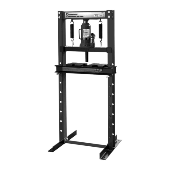
- Page 1 12 TON HYDRAULIC SHOP PRESS OWNER’S MANUAL WARNING: Read carefully and understand all ASSEMBLY AND OPERATION INSTRUCTIONS before operating. Failure to follow the safety rules and other basic safety precautions may result in serious personal injury. Item# 46270...
-
Page 2: Intended Use
Thank you very much for choosing a Strongway product! For future reference, please complete the owner’s record below: Model: _______________ Purchase Date: _______________ Save the receipt, warranty and these instructions. It is important that you read the entire manual to become familiar with this product before you begin using it. -
Page 3: General Safety Rules
GENERAL SAFETY RULES WARNING: Read and understand all instructions. Failure to follow all instructions listed below may result in serious injury. CAUTION: Do not allow persons to operate or assemble this Jack until they have read this manual and have developed a thorough understanding of how the Jack works. WARNING: The warnings, cautions, and instructions discussed in this instruction manual cannot cover all possible conditions or situations that could occur. -
Page 4: Safety Markings
DO NOT OPERATE OR REPAIR THIS EQUIPMENT WITHOUT READING THIS MANUAL. To maintain the Shop Press and user safety, the responsibility of the owner is to read and follow these instructions. Inspect the service shop press for proper operation and function. Keep instructions readily available for equipment operators. - Page 5 PLEASE READ THESE INSTRUCTIONS CAREFULLY.NOTE SAFETY INSTRUCTIONS WARNING.USE THE PRODUCT CORRECTLY AND WITH CARE FOR THE PURPOSE OF WHICH IT IS INTENDED.FAILURE TO DO SO MAY CAUSE DAMAGE TO PROPERTY AND/OR SERIOUS PERSONAL INJURY. PLEASE KEEP THIS INSTRUCTION MANUAL SAFE FOR FUTURE USE. We’ve done all we can to assure this press offers the utmost in safety, but you have to do your part.
- Page 6 ASSEMBLY Use the exploded drawing as your guide to assemble, Lay all parts and assemblies out in front of you before beginning. The following procedure is recommended: All numbers in parenthesis () refer to the index number from the parts breakdown. 1.
- Page 7 3. Put the frame in an upright position, and attach the upper crossbeam (14) and attached the springs (15). Then attach eye hooks (17), using nuts (20) to middle bolster (18). The attach springs to middle bolster. (Middle Bolster will then suspend between left and right frame posts.) 4.
- Page 8 5. Insert lower bolster pins (8) into the holes in the posts. Then insert the lower bolster (7) into press frame and onto lower bolster pins. 6. Check that all fasteners are tightened and insert the handle into the handle socket. 7.
- Page 9 BOTTLE JACK ASSEMBLY 1. Familiarize yourself with the jack. 2. Attach the handle pieces making sure to align the holes on both the lowering valve and the handle socket. 3. Line up the handle to the handle socket located on the side of the jack, then insert the handle inside the handle socket.
- Page 10 2. Pump handle 6 to 8 full strokes. Leave handle in down position to expose oil fill plug. 3. Turn release valve clockwise to the closed position. 4. Pump handle until the ram reaches maximum height and continue to pump several times to remove trapped air in the ram.
- Page 11 5. Carefully and slowly pinch oil fill plug to release trapped air. 6. Turn release valve counterclockwise to the open position one full turn and lower ram to the lowest position. 7. Turn release valve (R7) clockwise to the closed position and check for proper pump action. It may be necessary to perform the above step more than once to assume air is evacuated totally.
-
Page 12: Before Use
BEFORE USE 1. Before using this product, read the owner's manual completely and familiarize yourself thoroughly with the product and the hazards associated with its improper use. 2. Perform the air purge procedure. (See previous instructions for system purge procedure.) 3. - Page 13 5. Insert jack handle into handle socket and pump until ram nears work piece. 6. Align ram and work piece to ensure center-loading. 7. Apply load to work piece by pumping handle. Do not overload work piece. 8. Stabilize work piece in a manner which will not allow it to inadvertently fall from the bed frame when the load is removed.
-
Page 14: Maintenance Instructions
MAINTENANCE INSTRUCTIONS If you use and maintain your equipment properly, it will give you many years of service. Follow the maintenance instructions carefully to keep your equipment in good working condition. Never perform any maintenance on the equipment while it is under a load. Inspection You should inspect the product for damage, wear, broken or missing parts (e.g.: pins) and that all components function before each use. - Page 15 TO ADD OIL: The hydraulic cylinder assembly contains hydraulic fluid that must be kept at approximately 80% full at all times for proper operation. To check the level and to fill remove oil filler plug. 1. Position the jack on level ground and lower the saddle. 2.
- Page 16 4. Replace oil plug. 5. Perform the Air Purge Procedure. TO REPLACE JACK OIL: 1. Position the jack on level ground and lower the saddle. 2. Open release valve by turning handle counter-clockwise (4 full turns).
- Page 17 3. Remove the oil fill plug. 4. Turn the jack on its side so that old oil will drain from the oil fill hole. Note: Dispose of hydraulic fluid in accordance with local regulations. 5. Position the jack on level ground and lower the saddle.
- Page 18 6. Fill the oil case until oil level is just beneath the lower rim of the oil fill hole. KEEP DIRT AND OTHER MATERIAL CLEAR WHEN POURING. 7. Replace oil plug. 8. Perform the Air Purge Procedure. ADDITIONAL WARNINGS: DO NOT USE MOTOR OIL IN THE JACK.
-
Page 19: Troubleshooting
LUBRICATION A periodic coating of light lubricating oil to pivot points will help to ensure that pump piston linkages move freely. Note: Never apply oil to the saddle. If saddle extension threads require lubrication; clean thread surfaces with a clean, dry cloth, then apply a drop of bearing grease to the threads. Distribute as evenly as possible along the threaded post. -
Page 20: Assembly Diagram
ASSEMBLY DIAGRAM PARTS LIST Index # Description Part Number. Qty. Nuts Bolt M12x110 GB5782 Washer 12 GB97.1 Spring Washer 12 GB93 Nuts M12 GB6170 Post TY12003-01 Bolster Plates TY12003-02 Lower Bolster TY12003.1 Lower Bolster Pins TY12003-03 Nuts Bolt M10x30 GB5783 Washer 10 GB97.1 Spring Washer 10... - Page 21 HYDRAULIC BOTTLE JACK ASSEMBLY DIAGRAM AND PARTS LIST Index # Description Part Number. Qty. Index # Description Part Number. Qty. QYL10-04 Top Cap QYL10-17 Piston 42.5X3.55G O-Ring QYL12.5D-06 Piston Rod QYL10-03 Rectangular Ring QYL10-02A Screw Thread T91203.1 Reservoir QYL10-01A Extension Screw TF1201C-29 Oil Plug T91203-33...
-
Page 22: Replacement Parts
Safe Operating Temperature is between 40°F – 105°F (4°C - 41°C) REPLACEMENT PARTS For replacement parts Customer Service at 1-800-222-5381. Not all equipment components are available for replacement; illustrations provided are a convenient reference of location and position in the assembly sequence. - Page 23 Northern Tool and Equipment Company, Inc. ("We'' or '"Us'') warrants to the original purchaser only ("You'' or “Your”) that the Strongway product purchased will be free from material defects in both materials and workmanship, normal wear and tear excepted, for a period of one year from date of purchase.