Table of Contents
Advertisement
Quick Links
Advertisement
Table of Contents

Related Manuals for Comtrend Corporation GS-7405


Summary of Contents for Comtrend Corporation GS-7405
- Page 1 GS-7405 Smart- Lite Switch User Manual Version 1.0.0, December 2016...
- Page 2 FCC Compliance This equipment has been tested and found to comply with the limits for a Class B Digital Device, pursuant to part 15 of the FCC Rules. These limits are designed to provide reasonable protection against harmful interference in a residential installation. This equipment generates, uses and can radiate radio frequency energy and, if not installed and used in accordance with the instruction, may cause harmful interference to radio communication. However, there is no guarantee that interference will not occur in a particular installation. If this equipment does cause harmful interference to radio or television reception, which can be determined by turning the equipment off and on, the user is encouraged to try to correct the interference by one or more of the following measures: • Reorient or relocate the receiving antenna • Increase the separation between the equipment and receiver • Connect the equipment into an outlet on a circuit different from that to which the receiver is connected • Consult the dealer or an experienced radio/TV technician for help. The changes or modifications not expressly approved by the party responsible for compliance could void the user's authority to operate the equipment. To comply with the FCC RF exposure compliance requirements, this device and its antenna must not be co-located or operating to conjunction with any other antenna or transmitter. This equipment should be installed and operated with minimum distance 20cm between the radiator & your body. Copyright Copyright© 2017 Comtrend Corporation. All rights reserved. The information contained herein is proprietary to Comtrend Corporation. No part of this document may be translated, transcribed, reproduced, in any form, or by any means without the prior written consent of Comtrend Corporation. This program is free software: you can redistribute it and/or modify it under the terms of the GNU General Public License as published by the Free Software Foundation, either version 3 of the License, or (at your option) any later version. This program is distributed in the hope that it will be useful, but WITHOUT ANY WARRANTY; without even the implied warranty of MERCHANTABILITY or FITNESS FOR A PARTICULAR PURPOSE. See the GNU General Public License for more details. You should have received a copy of the GNU General Public License along with this program. If not, see http://www.gnu.org/licenses/ NOTE: This document is subject to change without notice.
- Page 3 Protect Our Environment This symbol indicates that when the equipment has reached the end of its useful life, it must be taken to a recycling center and processed separately from domestic waste. The cardboard box, the plastic container in the packaging, and the parts that make up this router can be recycled in accordance with regionally established regulations. Never dispose of this electronic equipment along with your household waste; you may be subject to penalties or sanctions under the law.
-
Page 4: Table Of Contents
Table of Contents Contents ........................ 4 Table of Contents Safety and Regulatory ......................5 Audience ........................5 Conventions ........................5 Introduction ........................6 Overview ........................6 Package contents ......................6 Features ........................6 Product Components ......................7 Switch Views ........................7 LED Indicators ......................... 7 Installation ........................9 Desktop Installation ......................9 Getting Started ........................ -
Page 5: Safety And Regulatory
Safety and Regulatory Audience This manual is for networking professionals managing the standalone GS-7405 gigabit network switch. It is recommended that only professionals with experience working with Comtrend’s networking devices attempt to configure this device. Experience with Ethernet and local area networking terminology and service equipment is recommend. Conventions The following conventions are used in this manual to convey instructions and information: Command descriptions use these conventions: • Commands and keywords are in boldface text. • Parameters for which you supply values are in italic text. • Square brackets ([ ]) mean optional elements. • Braces ({ }) group required choices, and vertical bars ( | ) separate the alternative elements. • Braces and vertical bars within square brackets ([{ | }]) mean a required choice within an optional element. Interactive examples use these conventions: • Nonprinting characters, such as passwords or tabs, are in angle brackets (< >). Notes and cautions use the following conventions and symbols: Note: Means additional information. Notes contain additional useful information or references to material available outside of this document. Caution: Indicates that the reader must be careful. In a situation where a Caution is listed, a user may cause equipment damage or loss of data. -
Page 6: Introduction
Introduction Thank you for purchasing a Comtrend Gigabit Ethernet Smart-Lite switch. The GS-7405 is powered by Comtrend’s Web Smart interface. This document is intended to provide hardware installation instructions as well as an overview of the interface and management functions of the Web Smart web-based software. Overview The Comtrend GS-7405 is a fanless smart-lite switch supporting 5 Gigabit Ethernet ports. Package contents Before using the product, check that the items listed below are included and in good condition. If any items are missing, please contact your dealer. • Comtrend GS-7405 Gigabit Ethernet Switch • External Power Adapter • Quick Installation Guide • Manual CD • Foot pads Features • Supports up to 5 10/100/1000Mbps Gigabit Ethernet ports • IEEE 802.1Q VLAN allows network segmentation to enhance performance and security • IEEE 802.1p QoS with 4 priority queues • Supports access control list (ACL) • Switch capacity: 10Gbps, forwarding rate: 11.9Mbps • Supports IGMP Snooping V1 / V2 / V3 • 2K MAC address table and 9K jumbo frames... -
Page 7: Product Components
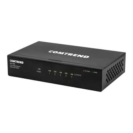
Product Components Switch Views The following view applies to the GS-7405. GS-7405 Rear View No. Name Description Reset button Press (10 sec.) to restore factory default parameters. Designed to connect to network devices with a bandwidth of 10Mbps, Ethernet (LAN) ports 100Mbps or 1000Mbps. Each has a corresponding 10/100/1000Mbps LED. DC power in Supports 5V DC/1A LED Indicators The following view applies to the GS-7405. 1000M 10/100M LINK/ACT... - Page 8 GS-7405 LED Indicators No. Name Description Green LED: • Off: power off or fail • On: power on Power • Blinking: system rebooting LINK/ACT bi-color LED: • Off: port disconnected or link fail • Green on: 1000M connected • Port LED Amber on: 10/100M connected • Blinking: sending or receiving data...
-
Page 9: Installation
Installation This chapter describes how to install and connect your Comtrend GS-7405 Switch. Read the following topics and perform the procedures in the indicated order. Incorrect installation may cause damage to the product. Placement Tips • Ambient Temperature - To prevent the switch from overheating, do not operate it in an area that exceeds an ambient temperature of 122°F (50°C). • Air Flow - Assure that there is adequate air flow around the switch. • Mechanical Loading - Assure that the switch is level and stable to avoid any hazardous conditions. • Circuit Overloading – Avoid powering the switch from an overloaded power circuit. Desktop Installation To place the switch on a desktop: Install the four foot pads (included) on the bottom of the switch. Place the switch on a flat surface. Desktop Installation... -
Page 10: Getting Started
Getting Started This section provides an introduction to the web-based configuration utility, and covers the following topics: • Powering on the device • Connecting to the network • Starting the web-based configuration utility Power Installing Power Power down and disconnect the power cord before wiring a switch. Do not disconnect modules or cabling unless the power is first switched off. The device only supports the voltage outlined in the type plate. Do not use any other power components except those specifically designated for the switch. Disconnect the power cord before installation or cable wiring. The Gigabit Ethernet Smart-Lite switch is powered by an external power adapter (5V DC/1A). Connect the power adapter to an external power source and check the power LED is on. -
Page 11: Connecting To The Network
Connecting to the Network To connect your switch to the network: Connect the switch to local power with the included power adapter. Use a standard Cat 5/5e Ethernet cable to connect the switch to end devices as shown below. Switch ports will automatically adjust to the link rate of the device to which it’s connected. Optionally, any port can be used to uplink to an existing network. Application Diagram Switch Gateway VoIP Access Phone Camera Point... -
Page 12: Browser Restrictions
Starting the Web-based Configuration Utility This section describes how to navigate the web-based switch configuration utility. If you are using a pop-up blocker, make sure it is disabled. Browser Restrictions • If you are using older versions of Internet Explorer, you cannot directly use an IPv6 address to access the device. You can, however, use the DNS (Domain Name System) server to create a domain name that contains the IPv6 address, and then use that domain name in the address bar in place of the IPv6 address. • If you have multiple IPv6 interfaces on your management station, use the IPv6 global address instead of the IPv6 link local address to access the device from your browser. Launching the Configuration Utility To open the web-based configuration utility: Open a Web browser. Enter the IP address of the device you are configuring in the address bar on the Browser (the factory default IP address is 192.168.169.1) and then press Enter. Your computer’s IP address must be in the same subnet as the switch. For the default IP address this is any IP address in the range 192.168.169.x (x= 2 – 254). Modify the IP address of your computer as need. The login window displays. -
Page 13: Logging In
Logging In To log in to the device configuration utility: Enter the default user ID (admin) and the default password ( admin). If this is the first time that you logged on with the default user ID (admin) and the default password (admin) it is recommended that you change your password immediately. See Password for additional information. When the login attempt is successful, the System Status window displays. If you entered an incorrect username or password, the “Login” page remains displayed on the window. If you are having problems logging in, please see the “Launching the Configuration Utility” section in the User Manual for additional information. -
Page 14: Logging Out
Logging Out By default, the application logs out after ten minutes of inactivity. To manually logout, click Logout on the bottom of the menu sidebar. When a timeout occurs or you intentionally log out of the system, a message appears and the Login page appears, with a message indicating the logged-out state. After you log in, the application returns to the initial page. -
Page 15: Web-Based Switch Configuration
Web-based Switch Configuration The Smart-Lite switch software provides rich Layer 2 functionality for switches in your network. This chapter describes how to use the web-based management interface (Web UI) to configure the switch’s features. For the purposes of this manual, the user interface is separated into two sections, as shown in the following figure: No. Name Description Configuration menu Navigate to locate specific switch functions. Configuration settings Edit specific function settings. -
Page 16: System
System Use this page to view status information such as Device Name, MAC address, IP Address and Firmware Version. To view the System menu, navigate to System. Item Description Model Name Switch model name. Device Name System name of the switch. Configurable per user’s convenience. Firmware Version Current firmware version of the device. Build Date Device production date. A unicast MAC address for which the switch has forwarding and/or filtering information. The format is a six-byte MAC address, with each byte separated by MAC Address colons. IPV4 Address Switch IPV4 address on the network. Subnet Mask A 32-bit number that masks an IP address. Loop Status Displays whether or not loops exist in the network. -
Page 17: Management
Management Use this page to reset the switch to original factory default settings, reboot the switch, backup and restore switch settings and upgrade firmware. To view the Management menu, navigate to Management. Item Description Management Reset Restore switch to original factory default settings. Reboot Reboot switch. Configuration Restore/Backup Click to browse a remote TFTP server or on local storage, to locate a file with Choose File a previously saved switch setting configuration. Restore Install selected switch setting configuration file. Backup Save current switch setting configuration as a backup file. Firmware Upgrade Click to “Upgrade” enter “Loader Mode”. Once in “Loader Mode”, click “Choose File” and navigate to the firmware file you intend to load. Click “Upgrade” to being Upgrade the firmware upgrade process. -
Page 18: Port
Port Use this page to view traffic information such as Link Status, TX, RX, Loop Status and Loop Reset, on each port. The tracking data on each port can also be reset. To view the Port menu, navigate to Port. Item Description Port Designated port number. Displays whether or not port is in use and link speed if it is in use. Link Status The total number of packets transmitted by the port. The total number of packets received by the port. Clear Counters Click to reset tracking data. -
Page 19: Vlan
VLAN Use this section to create and modify VLANs. IEE 802.1Q VLAN To view the IEE 802.1Q VLAN menu, navigate to VLAN > IEE 802.1Q VLAN. Item Description IEE 802.1Q VLAN Click to enter IEE 802.1Q VLAN settings. Port-Based VLAN Click to enter port-based VLAN settings. Apply Click Apply to save the values and update the screen. Port Designated port number. PVID Enter a VLAN ID for each port. Create New VLAN Click Create New VLAN to enter new VLAN settings. VLAN ID Virtual LAN ID. Non-Member Port is not a member of a VLAN. Tag Egress Member Tag outgoing packets of a port that is a member of the VLAN. Untag Egress Untag outgoing packets of a port that is a member of the VLAN. Member Modify Modify port settings of a specific VLAN. Delete Delete a specific VLAN. - Page 20 Port-Based VLAN To view the Port-Based VLAN menu, navigate to VLAN > Port-Based VLAN. Item Description Add VLAN Click Add VLAN to enter new VLAN settings. Apply Click Apply to save the values and update the screen. Member Port Click to assign specific ports as members of a VLAN. Group ID Identifier of the group of ports in a VLAN. Delete a specific VLAN. Delete...
-
Page 21: Trunking
Trunking Use this option to aggregate multiple Ethernet ports together to form a logical port. This feature supports static allocation and Link Aggregation Control Protocol (LACP). To view the Trunking menu, navigate to Trunking. Item Description Apply Click Apply to save the values and update the screen. LACP Global State Enable/disable LCAP. Select a link aggregation algorithm: • MAC SA & DA: distribute traffic based on a combination of the packet’s source and destination MAC addresses. Link Aggregation Algorithm • MAC DA: distribute traffic based on the packet’s destination MAC • MAC SA: distribute traffic based on the packet’s source MAC address. Select link group activity status: • Passive Link Group Activity • Active Link Group Members The ports that are members of a port channel. 1. You must connect all ports point-to-point to the same Ethernet switch and configure the ports for LACP trunking. 2. LACP only works on full-duplex links. 3. All ports in the same trunk group must have the same media type, speed, duplex mode and flow control settings. 4. Configure trunk groups or LACP before you connect the Ethernet switch to avoid causing network topology loops. -
Page 22: Mirror
Mirror Port mirroring selects the network traffic for analysis by a network analyzer. This is done for specific ports of the switch. As such, many switch ports are configured as source ports and one switch port is configured as a destination port. To view the Mirror menu, navigate to Mirror. Item Description Enable Mirror Enable/disable port mirroring. Select the mirror direction: • Ingress Mirror Direction • Egress Monitor Port Select the mirror destination port. The ports or configured to mirror traffic to the destination. Multiple source Mirrored Port List ports can be configured. Apply Click Apply to save the values and update the screen. -
Page 23: Qos
QoS Use this section to configure Quality of Service (QoS) settings. Disable QoS To view the Disable QoS menu, navigate to QoS > Disable QoS. Item Description Disable QoS Enable/disable QoS. Port-Based Qos Click to select port-based QoS settings. IEEE 802.1p QoS Click to enter IEE 802.1Q QoS settings. Port-Based QoS To view the Port-Based QoS menu, navigate to QoS > Port-Based QoS... - Page 24 Item Description Disable QoS Enable/disable QoS. Port-Based Qos Click to select port-based QoS settings. IEEE 802.1p QoS Click to enter IEE 802.1Q QoS settings. Port Designated port number. Queue priority value. More packets are sent from a queue with a higher weight value. Weight Queues used to store traffic until it can be processed or Queue 0-3 serialized. IEEE 802.1p QoS To view the IEEE 802.1p QoS menu, navigate to QoS > IEEE 802.1p QoS.
-
Page 25: Broadcast Storm Control
Item Description Disable QoS Enable/disable QoS. Port-Based Qos Click to select port-based QoS settings. IEEE 802.1p QoS Click to enter IEE 802.1Q QoS settings. Port Designated port number. Queue priority value. More packets are sent from a queue with a higher weight value. Weight Queues used to store traffic until it can be processed or Queue 0-3 serialized. Broadcast Storm Control This page allows you to set ingress port monitoring. To view the Broadcast Storm Control menu, navigate to Broadcast Storm Control. Item Description Set Broadcast storm control limit: • No limit Broadcast • 512K/s to 512M/s Set Multicast storm control limit: • No limit Multicast • 512K/s to 512M/s Set DLF storm control limit: • No limit DLF • 512K/s to 512M/s Apply Click Apply to save the values and update the screen. -
Page 26: Rate Limiting
Rate Limiting This page allows you to display and configure ingress and egress port monitoring settings. Rate Limiting This page displays ingress and egress port limits. To view the Rate Limiting menu, navigate to Rate Limiting. Item Description Designated port number. Click individual port numbers to enter rate limit Port configuration menu for each port. Ingress rate The upper limit on how much traffic can enter a port. Egress rate The upper limit on how much traffic can exit a port. - Page 27 Change Rate Limit Use this page to configure ingress and egress rate limit settings. To view the Change Rate Limit menu, navigate to Rate Limiting > port number. Item Description Apply Click Apply to save the values and update the screen. Port Designated port number. Select to configure the upper limit on how much traffic can enter a port: • No limit Ingress rate • 512K/s to 512M/s Select to configure the upper limit on how much traffic can exit a port: • No limit Egress rate • 512K/s to 512M/s...
-
Page 28: Loop Detect/Prevent
Loop Detect/Prevent Use this section to enable/disable and configure network routing loop detection. Select the desired setting from the drop down menu. To view the Loop Detection/Prevention menu, navigate to Loop Detection/Prevention. Item Description Off Disable loop detection and prevention. Enable loop detection. When it detects a loop, this feature does not repair the Loop Detection loop, but only issues a warning. Enable loop prevention. When it detects a loop, this feature will disable loop Loop Prevention ports and down port LED, and the system LED will be blinking. Apply Click Apply to save the values and update the screen. -
Page 29: Igmp Snooping
IGMP Snooping Use this section to create an IGMP Snooping Profile. Internet Group Management Protocol (IGMP) Snooping is a feature that allows a switch to forward multicast traffic intelligently on the switch. Multicast IP traffic is traffic that is destined to a host group. Host groups are identified by class D IP addresses, which range from 224.0.0.0 to 239.255.255.255. Based on the IGMP query and report messages, the switch forwards traffic only to the ports that request the multicast traffic. This prevents the switch from broadcasting the traffic to all ports and possibly affecting network performance. To view the IGMP Snooping menu, navigate to IGMP Snooping. Item Description Blocking Unknown Multicast Block unknown multicast packets. Enable IGMP Enable/disable IGMP snooping. Snooping Select a static port on which to snoop, either No Static Router Port, or one of IGMP Static Router Port ports 1-5. Apply Click Apply to save the values and update the screen. -
Page 30: Password
Password Use these settings to change an account password. To view the password menu, navigate to Password. Item Description Confirm Click Confirm to save the values and update the screen. Old Password, New User Name Enter new user name. New Password Enter new password. Confirm New Enter new password again to confirm. Password Logout Click Logout to leave the switch management menu and close the web management session. FOR MORE INFORMATION: YouTube: https://www.youtube.com/user/ComtrendConnection Facebook: https://facebook.com/Comtrend Website: http://us.comtrend.com/ Support: Visit our website or call 1-877-COMTREND (1-877-266-8736)