
Related Manuals for Comtrend Corporation PowerGrid-9171n


Summary of Contents for Comtrend Corporation PowerGrid-9171n
- Page 1 PowerGrid-9171n Powerline Ethernet Adapter User Manual Version A2.0, November 3, 2015 261072-035...
- Page 2 Comtrend Corporation. No part of this document may be translated, transcribed, reproduced, in any form, or by any means without prior written consent of Comtrend Corporation. This program is free software: you can redistribute it and/or modify it under the terms of the GNU General Public License as published by the Free Software Foundation, either version 3 of the License, or (at your option) any later version.
- Page 3 Protect Our Environment This symbol indicates that when the equipment has reached the end of its useful life, it must be taken to a recycling centre and processed separate from domestic waste. The cardboard box, the plastic contained in the packaging, and the parts that make up this Ethernet Adapter can be recycled in accordance with regionally established regulations.
-
Page 4: Table Of Contents
Table of Contents Chapter 1 Product Information..........................5 1.1 Front Panel and LED indicators ........................5 1.2 Bottom Panel .............................6 1.3 How to understand the COVERAGE LED colors ..................7 1.4 Point-to-Point Network..........................8 1.5 Point to Multipoint Network ........................9 Chapter 2 Log In Procedure ..........................10 2.1 Configure STATIC IP MODE........................10 2.2 Logging In..............................11 Chapter 3 G.hn Interface ...........................12... - Page 5 13.5.1 Time Zone Setting ...........................37 13.5.2 Password............................38 13.5.3 TR-069 Client...........................39 13.5.4 LAN Settings............................41 13.6 Wireless ..............................42 13.6.1 Basic settings ..........................42 13.6.2 Advanced settings...........................45 13.6.3 Security settings..........................47 13.6.4 Access Control ..........................50 13.6.5 WPS..............................51 13.7 Tools ...............................53 13.7.1 Configuration Tools.........................53 13.7.2 Firmware Upgrade ..........................54 13.7.3 Factory Defaults ..........................55...
-
Page 6: Chapter 1 Product Information
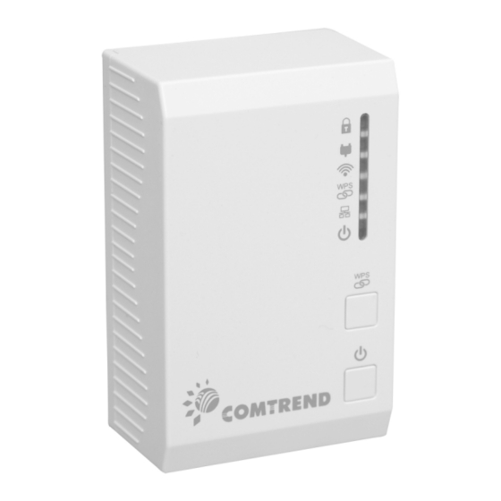
Chapter 1 Product Information 1.1 Front Panel and LED indicators WPS Button: Press for 2 – 10 seconds to start the WPS function. Press for over 10 seconds to reset to factory defaults. Power Button: Push once to power up the PG-9171n Push once to power down the PG-9171n COLOR MODE... -
Page 7: Bottom Panel
WPS function is disabled or there is no activity Green Blink There is activity occurring LAN connection established Ethernet LAN connection is not established Green Blink Data transmitting/receiving Power The device is powered up Green The device is powered down 1.2 Bottom Panel Item Name Description... -
Page 8: How To Understand The Coverage Led Colors
1.3 How to understand the COVERAGE LED colors The COVERAGE LED displays quality of the network and provides important information that will provide solutions to common questions, such as why a High Definition (HD) movie is not showing or shows with pixels. The COVERAGE LED indicator will vary its color depending on the estimated speed of the Powerline connection. -
Page 9: Point-To-Point Network
1.4 Point-to-Point Network CASE 1: Estimated throughput is less than 20 Mbps. The PLC channel is not able to transmit an SDTV channel. The COVERAGE LED will be RED as shown in the following figure: CASE 2: Estimated throughput is greater than 20 Mbps but less than 40 Mbps. The PLC channel is able to transmit an SDTV channel, but not two SDTV channels simultaneously or one HDTV channel. -
Page 10: Point To Multipoint Network
1.5 Point to Multipoint Network In the case where the PLC network is composed of three or more adapters, similar situations could arise as with a point-to-point network. CASE 1: The COVERAGE LED in G.hn adapter 2 and G.hn adapter 3 will show the estimated level of ... -
Page 11: Chapter 2 Log In Procedure
Chapter 2 Log In Procedure 2.1 Configure STATIC IP MODE In static IP mode, you assign IP settings to your PC manually. Follow these steps to configure your PC IP address to use subnet 192.168.0.x. NOTE: The following procedure assumes you are running Windows XP. However, the general steps involved are similar for most operating systems (OS). -
Page 12: Logging In
2.2 Logging In Perform the following steps to login to the web user interface. STEP 1: Start the Internet browser and enter the default IP address for the device in the Web address field. For example, if the default IP address is 192.168.0.5, type http://192.168.0.5 STEP 2: A dialog box will appear, such as the one below. -
Page 13: Chapter 3 G.hn Interface
Chapter 3 G.hn Interface... -
Page 14: Basic Configuration
3.1 Basic Configuration MAC Address Displays the MAC address of the device. Device ID Device ID of this node. Domain Name string of all nodes in the network. Force node Type force the modem to have a particular role (END POINT or DOMAIN MASTER) ... -
Page 15: Chapter 4 Ip Interface
Chapter 4 IP Interface... -
Page 16: Ip Config
4.1 IP config In the IP configuration tab of one G.hn node, the IPv4 and IPv6 settings can be read and changed. IPv4 subsection: DHCPv4 enabled: in the case of choosing ”NO" IP configuration in the following parameters, the IPv4 Address, Subnet Mask, Default Gateway and DNS should be configured;... -
Page 17: Chapter 5 Ethernet Interface
Chapter 5 Ethernet Interface The Ethernet table shows the coverage & Info of the Ethernet interface; including Interface, Speed, Duplex, Interface Type, Mode, Internal PHY & Link. Powersaving Ethernet powersaving can be disabled, enabled by Ethernet link or enabled by Ethernet activity; idle timer can be configured as well. -
Page 18: Chapter 6 Device Interface
Chapter 6 Device Interface 6.1 Hardware information In this tab, basic information such as MAC Address and Serial Number of the selected node is shown. -
Page 19: Software Information
6.2 Software information Shows the FW version and system uptime. 6.3 Security The nodes in the network: to change the configuration password string from the default ("admin") to another; decided by the user. 6.4 SW update Current loaded firmware version is shown. Any flash section can be upgraded; the first flash section should be selected and after clicking on the "OK"... -
Page 20: Chapter 7 Multicast Interface
Chapter 7 Multicast Interface 7.1 MCAST Configuration In the MCAST Configuration tab of "My Network", IGMP snooping and MLD features can be enabled or disabled. Also, IGMP multicast IP addresses ranges which the G.hn PLC network will sniff; can be configured. -
Page 21: Chapter 8 Qos Menu
Chapter 8 QoS menu... -
Page 22: Qos Configuration
8.1 QoS Configuration In the QoS configuration tab, the packet classifier can be managed to define a QoS rule for incoming Ethernet traffic, and assign a priority to be used in the G.hn network. Press the “Ok" button for loading the newly configured settings: ... - Page 23 Example 1 If QoS criterion: 802.1p, all other options are grayed out, and follow the QoS rules below. According to G.9960 specs, the priority mapping recommended by [IEEE 802.1D] subclause 7.7.3 is presented in Table III.1. for four priority queues.
- Page 24 Priority Acronym Traffic Types 0 (Third) Background 1 (lowest) Best Effort 2 (lowest) Excellent Effort 3 (Third) Critical Applications 4 (second) Video, < 100 ms latency and jitter 5 (second) Voice, < 10 ms latency and jitter 6 (highest) Internetwork Control 7 (highest) Network Control In summary, the sequence of priority queue, (7,6) >...
-
Page 25: Chapter 9 Vlan Interface
Chapter 9 VLAN Interface 9.1 VLAN Configuration In the VLAN Configuration tab of one G.hn node, a VLAN tag can be added or removed per interface. Also, removing a tag at egress per interface can be also enabled or disabled: ... -
Page 26: Chapter 10 G.hn Spectrum Interface
Chapter 10 G.hn spectrum Interface 10.1 Notches In this tab a table with all configured Notches of selected node will be shown. The table is composed of next columns for every notch: Notch Number, Type of notch, Start Frequency (KHz), Stop Frequency (KHz), Depth (in dB). -
Page 27: Chapter 11 Log File Interface
The first 22 notches (Regulation) are Read Only, RO, in the system and they can be neither removed nor modified. The next 40 notches (Vendor) are defined by the vendor using SDK and they are also RO. The last 10 notches (User) are R/W and they can be added/removed by user using this tool. To add new notches the user should fill the "Add a new User Notch"... -
Page 28: Chapter 12 Advanced Interface
Chapter 12 Advanced Interface Broadcast suppression In this tab the broadcast suppression feature can be managed. Broadcast traffic higher than the selected value will be dropped. Hardware Reset: Click on this button to perform a reboot in the node. Factory Reset: Input the password: betera and click the OK button to perform a factory reset. The current configuration will be lost. -
Page 29: Chapter 13 Connecting To Pg-9171Nwireless-N Powerline Adapter By Web Browser
Chapter 13 Connecting to PG-9171nWireless-N Powerline Adapter by web browser After the network connection is complete, the next step you should perform is to setup the Wireless-N Powerline Adapter with proper network parameters, so it can work properly in your network environment. Before you can connect to the Wireless-N Powerline Adapter and start configuration procedures, your computer must be able to get an IP address automatically (use dynamic IP address). -
Page 30: Windows 7 Ip Address Setup
13.1 Windows 7 IP address setup 1. Click the Start button and select Control Panel. Double click Network and Internet and click Network and Sharing Center, the Network and Sharing Center window will appear. 2. Click Change adapter settings and right click on the Local Area Connection icon and select Properties. The Local Area Connection window will appear. -
Page 31: Connecting To Web Management Interface
13.2 Connecting to Web Management Interface All functions and settings of this Wireless-N Powerline Adapter must be configured via web management interface. Please start your web browser, and input ‘192.168.0.10’ in the address bar, then press ‘Enter’ key. The following should be displayed: Input the user name and password in the respective fields, default user name is ‘root’, and default password is ‘12345’, then press the ‘OK’... -
Page 32: Quick Setup
13.3 Quick Setup After login, the Quick Setup screen will appear. It is the default screen when no connections exist. This screen allows for the configuration of DSL settings and the IP configuration. It includes LAN, Wireless and Security setup screens. NOTE: If you can’t see the web management interface, and you’re being prompted to input user name and password again, it means you didn’t input the username and password correctly. -
Page 33: Wireless Settings
13.3.2 Wireless Settings This page is used to configure the parameters for the wireless connection of tablets, smart phones, and laptops. Click the Next button to continue. Band Select the wireless band you wish to use. By selecting a different band setting, you’ll be able to allow or deny the wireless client of a certain band. -
Page 34: Security Settings
Control Specify if the extension channel should be in the Upper or Sideband Lower sideband. Channel Select a channel number (“Auto” is recommended). Number Please select a channel number you wish to use. If you know a certain channel number is being used by other wireless access points nearby, please refrain from using the same channel number. -
Page 35: Status
13.4 Status 13.4.1 Device Status This page shows the current status and some basic settings of the device. Up time Displays the total time passed since the Wireless-N Powerline Adapter was powered on. Firmware Version Displays Firmware version of wireless Wireless-N Powerline Adapter. -
Page 36: System Log
IP Address Displays the IP address of this Wireless-N Powerline Adapter. Subnet Mask Displays the net mask of IP address. Default Gateway Displays the IP address of default gateway. Displays the IP address of the DNS server. MAC address Displays the MAC address of WLAN interface. 13.4.2 System Log This page shows the system's operational information;... -
Page 37: Statistics
13.4.3 Statistics This page shows the packet count for the Wireless and Ethernet LAN. Wireless LAN It shows the statistic count of sent packets on the Sent Packets wireless LAN interface Wireless LAN It shows the statistic count of received packets on the Received Packets wireless LAN interface Ethernet LAN... -
Page 38: General Setup
13.5 General Setup 13.5.1 Time Zone Setting Automatically synchronize your Wireless-N Powerline Adapter time with Internet time servers. Select your local time zone from the drop-down menu. This page is used to configure NTP client to get current time. After clicking ‘Time Zone’ on the left of web management interface and the following will be displayed: Time Zone Select Select the time zone in your country Automatically Adjust... -
Page 39: Password
13.5.2 Password This page is used to set the account to access the web server of your Wireless-N Powerline Adapter. Emptying the user name and password fields will disable the protection. Click the Apply Changes button to create the new password setting. Click the Reset button to reset/clear the data just input on screen. -
Page 40: Tr-069 Client
13.5.3 TR-069 Client WAN Management Protocol (TR-069) allows an Auto-Configuration Server (ACS) to perform auto-configuration, provision, collection, and diagnostics of this device. Select desired values and click Apply Changes to configure TR-069 client options. ACS URL URL for the CPE to connect to the ACS using the CPE WAN Management Protocol. - Page 41 ACS Password Password used to authenticate the CPE when making a connection to the ACS using the CPE WAN Management Protocol. This password is used only for HTTP-based authentication of the CPE. Periodic Inform Whether or not the CPE periodically sends CPE information Enable to the ACS.
-
Page 42: Lan Settings
13.5.4 LAN Settings Enable your Wireless-N Powerline Adapter to dynamically receive an IP Address from your home gateway. Your Wireless-N Powerline Adapter must have an IP Address in the Local Area Network's existing IP range. IP Address The IP address for the Wireless-N Powerline Adapter. Subnet Mask The Subnet Mask for the Wireless-N Powerline Adapter. -
Page 43: Wireless
13.6 Wireless 13.6.1 Basic settings This page is used to configure the parameters for the wireless connection of tablets, smart phones, and laptops. Disable Wireless Clicking it will disable your Wireless LAN Interface. The LAN interface Wireless Interface default is Enable. Band Please select the wireless band you wish to use. - Page 44 Mode PG-9171nsupports not only AP mode, but also provides WDS, AP+WDS. Please refer to below for detailed wireless Basic Settings. In Default, PG-9171n will work with AP mode. Network Type In Infrastructure Mode, wireless clients can access the other networks (perhaps Internet) via this AP. For AP. Only Infrastructure Mode is allowed here.
- Page 45 After you finish with the settings, please click ‘Apply Changes’, and the following message will be displayed: When you see this message, the settings you made are successfully saved. You can click the ‘Reboot Later’ button to back to previous page and continue on other setting items, or click the ‘Reboot Now’ button to restart the Wireless-N Powerline Adapter and the changes will take effect after about 30 seconds.
-
Page 46: Advanced Settings
13.6.2 Advanced settings This Wireless-N Powerline Adapter has many advanced wireless features. Please note that all settings listed here are for experienced users only, if you’re not sure about the meaning and function of these settings, please don’t modify them, or the wireless performance will be reduced. You can click ‘Advanced Settings’... - Page 47 Short GI Click to enable or disable the Short GI function. STBC Click to enable or disable the STBC function. LDPC Click to enable or disable the LDPC function. 20/40MHz Coexist Click to enable or disable the 20/40MHz Coexist function. TX Beamforming Click to enable or disable the TX Beamforming function.
-
Page 48: Security Settings
13.6.3 Security settings This Wireless-N Powerline Adapter provides many types of wireless security (wireless data encryption). When you use data encryption, data transferred by radio signals in the air will become unreadable for those people who don’t know correct encryption key (encryption password). You can click ‘Security Settings’... - Page 49 13.6.3.1 Disable Security When you select ‘Disable’, wireless encryption for the network is disabled. 13.6.3.2 WEP WEP (Wired Equivalent Privacy) is a common encryption mode, it’s safe enough for home and personal use. But if you need higher level of security, please consider using WPA encryption (see next Section). However, some wireless clients don’t support WPA, but only support WEP, so WEP is still a good choice for you if you have such kind of client in your network environment.
- Page 50 Key Format There are two types of key format: ASCII and Hex. When you select a key format, the number of characters of the key will be displayed. For example, if you select ’64-bit’ as key length, and ‘Hex’ as key format, you’ll see the message at the right of ‘Key Format’...
-
Page 51: Access Control
13.6.4 Access Control Another security measure you can use to keep hackers and intruders away is ‘Access Control’. You can pre-define a so-called ‘white-list’, which contains MAC addresses of the wireless clients you trust. All other wireless client with the MAC address which is not in your list will be denied by this Wireless-N Powerline Adapter. -
Page 52: Wps
13.6.5 WPS Wi-Fi Protected Setup (WPS) is the simplest way to build a connection between wireless network clients and this Wireless-N Powerline Adapter. You don’t have to select encryption mode and input a long encryption passphrase every time when you need to setup a wireless client, you only have to press a button on wireless client and this Wireless-N Powerline Adapter, and the WPS will do the setup for you. - Page 53 Disable WPS Check this box to enable or disable the WPS function. WPS Status Displays WPS status. If data encryption settings of this Wireless-N Powerline Adapter have never been set, the ‘unConfigured’ message will be displayed here; if data encryption settings have been set before, the ‘Configured’...
-
Page 54: Tools
13.7 Tools 13.7.1 Configuration Tools Use the "Backup" tool to save the current configuration of your Wireless-N Powerline Adapter to a file named "config.dat". You can then use the "Restore" tool to recover the saved configuration to your Wireless-N Powerline Adapter. Click the Backup button to display the following. -
Page 55: Firmware Upgrade
13.7.2 Firmware Upgrade This page allows you upgrade the Wireless-N Powerline Adapter firmware to the new version. Please note, do not power off the device during the upload as it may crash the system. After clicking ‘ Upgrade Firmware’ on the left of web management interface and the following will be displayed: Click the Browse button to locate the file. -
Page 56: Factory Defaults
13.7.3 Factory Defaults This page allows you to reset the current configuration to factory defaults. Click the Apply button to reset the configuration.