Table of Contents
Advertisement
Available languages
Available languages
Quick Links
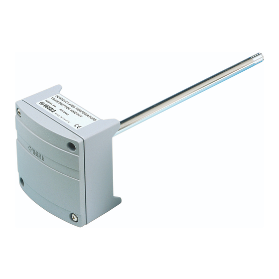
HUMIDITY TRANSMITTER HMD70U
HUMIDITY AND TEMPERATURE TRANSMITTER HMD70Y
MOUNTING
62 (2.44)
250 (9.84)
Ø 12 (0.47)
Figure 1: Dimensions of the HMD70U/Y
GROUNDING
Figure 2: Signal cable grounding
HMD70U/Y Operating Manual
100 (3.94)
<<< Mounting hole
82 (3.23)
The HMD70U/Y duct mounted humidity
and temperature transmitters are three-
wire transmitters. Mount the transmitter
with two screws. Place the drilling
template on the duct surface and drill the
holes as indicated. Remember to drill an
additional hole for calibration purposes.
The calibration can be conveniently
performed on site with the HMI41 or
HM70 indicator equipped with an
appropriate probe and optional
calibration cable.
Open the lid and mount the cable bushing
set 18941HM. Ground the cable by
connecting the contact tongues inside the
bushing to an exposed length of cable
braid as shown in Figure 2.
short-circuit risk, do not expose more
cable
braid
than
connecting the braid to the contact
tongues.
*M210277EN*
M210277EN-C
To minimize
is
necessary
for
1
Advertisement
Table of Contents

Related Manuals for Vaisala HMD70U


Summary of Contents for Vaisala HMD70U
- Page 1 HMI41 or <<< Mounting hole 82 (3.23) HM70 indicator equipped with an appropriate probe and optional Figure 1: Dimensions of the HMD70U/Y calibration cable. GROUNDING Open the lid and mount the cable bushing set 18941HM. Ground the cable by...
-
Page 2: Electrical Connections And Installation Of The Current Module
DC/AC power supply Figure 3: Electrical connections and installation of the current module CONNECTION TO AN AC SUPPLY HMD70U/Y transmitter The HMD70U/Y transmitters can also be Controller RH/T connected to an AC supply without an signal external rectifier. However, when more... - Page 3 If and a fast response time for the sensor. adjustment is necessary, use the humidity Do not attempt to clean the filter. offset potentiometer. If you prefer to calibrate the HMD70U/Y transmitters...
-
Page 4: Technical Data
18945HM. GUARANTEE 0...1 V 10...35 V 9...24 V Vaisala issues a guarantee for the material and 0...5 V 14...35 V 12...24 V workmanship of this product under normal operating 0...10 V 19...35 V 16...24 V conditions for one year from the date of delivery. -
Page 5: Montage
Sehen Sie eine zusätzliche Bohrung für (0.74) Kalibrierungen vor. Die Kalibrierung <<<Montageloch 82 (3.23) läßt sich sehr bequem mit dem Hand- Abb. 1: Abmessungen des HMD70U/Y meßgerät HMI41, einer entsprechenden Sonde und einem optionalen Kalibrier- kabel durchführen. ERDUNG DES ANSCHLUSSKABELS Öffnen Sie den Deckel und montieren Sie... - Page 6 VERSORGUNG Abbildung 3: Elektrische Anschlüsse und Installation des Strommoduls ANSCHLUSS AN EINE AC VERSORGUNG HMD70U/Y Steuergerät Die Meßwertgeber HMD70U/Y können RH/T ohne externen Gleichrichter auch an eine Signal 24 VAC AC Versorgung angeschlossen werden. Wenn aber mehr als ein Meßwertgeber an...
- Page 7 HMD70U/Y Bedienungsanleitung M210277EN-C DECKEL AUSBAU DER SONDE UND ELEKTRONIK: 1. Öffnen Sie den Gehäusedeckel. 2. Ziehen Sie die Schraubklemme von ihrem Sockel. 3. Lösen Sie die 2 Befestigungsschrauben. SCHRAUBKLEMME SCHRAUBEN 4. Ziehen Sie die Sonde vorsichtig aus dem Gehäuse. EINBAU DER SONDE UND ELEKTRONIK: 1.
-
Page 8: Technische Daten
0...5 V 14...35 V 12...24 V 0...10 V 19...35 V 16...24 V Vaisala gewährt eine Garantie auf Material und 0...20 mA (R L = 0 Ω) 10...35 V 11...24 V Verarbeitung dieses Produktes bei Betrieb unter 0...20 mA (R L = 500 Ω) 20...35 V 17...24 V... - Page 9 (0.47) grâce à l'indicateur portable HMI41 équipé de la sonde appropriée et le câble 100 (3.94) de calibration (en option). Mounting hole 82 (3.23)>>> Schéma 1 Dimensions de la HMD70U/Y BLINDAGE Ouvrez couvercle installez l'ensemble de presse-étoupe 18941HM. Reliez le câble à la terre en connectant les languettes de contact à...
- Page 10 T OFFSET T GAIN V/mA V/mA DC/AC alimentation Schéma 3: Connexions électriques et installation du module courant A) PAS DE BOUCLE DE COURANT - RECOMMANDE Les transmetteurs HMD70U/Y peuvent HMD70U/Y controleur être connectés à une alimentation AC RH/T sans redresseur externe.
- Page 11 N'essayez pas de nettoyer le filtre. et le câble de calibration. Si un ajustage est nécessaire, utilisez le potentiomètre offset de l'humidité. Si vous préférez calibrer les transmetteurs HMD70U/Y acev des solutions salines saturées, utilisez les solutions LiCl (11 %HR) et NaCl (75 %HR).
-
Page 12: Fiche Technique
Pour la sortie courant, il faut utiliser un module courant en option, réf. 18945HM. Vaisala garantit le matériel et la main d'oeuvre de ce produit dans les conditions normales d'utilisation pour un (1) an à partir de la date de livraison. Les 0...1 V... - Page 13 отверстия, как показано на рисунке. Также необходимо просверлить еще одно отверстие для калибровки. Калиб- Монтажное отверстие 82 (3,23) ровку можно выполнить на месте Рисунок 1. Размеры измерителя HMD70U/Y установки с помощью портативного индикатора HMI41 или HM70, оснащен- ного подходящим датчиком и дополни- тельным...
- Page 14 HMD70U/Y. Руководство по эксплуатации M210277EN-C ЭЛЕКТРИЧЕСКИЕ СОЕДИНЕНИЯ И УСТАНОВКА ТОКОВОГО МОДУЛЯ ВЫБОР ВЫХОДОВ УСТАНОВКА ТОКОВОГО МОДУЛЯ 18945HM 0—1 В 1. Снимите перемычки. 0—5 В 2. Подключите модуль. Проследите за правильной ориентацией! 0—10 В 3. Подключите источник питания. Токовый модуль ПРОВЕРОЧНЫЙ...
- Page 15 HMD70U/Y. Руководство по эксплуатации M210277EN-C СНЯТИЕ ГОЛОВКИ ДАТЧИКА 1. Откройте крышку. Крышка 2. Отсоедините винтовой зажим. 3. Открутите винты (2 шт.). 4. Аккуратно вытащите головку датчика. УСТАНОВКА ГОЛОВКИ ДАТЧИКА Винтовой зажим Винты 1. Вставьте головку датчика на место. 2. Затяните винты.
-
Page 16: Электромагнитная Совместимость
ГАРАНТИЯ каталогу 18945HM. Пост. ток Перем. ток 0—1 В 10—35 В 9—24 В Компания Vaisala предоставляет гарантию на материалы 0—5 В 14—35 В 12—24 В и качество изготовления данного прибора в течение 0—10 В 19—35 В 16—24 В одного года с момента поставки при работе... - Page 17 HMD70U/Y 取扱説明書 M210277EN-C 蓋を開け、ケーブルブッシングセット 18941HM を取り付けます。図 2 に示すと おり、ブッシング内の接点突起をケーブ ル編組の露出部分に接続して接地します 。 短絡が発生するリスクを最小限に抑える ために、編組を接点突起に接続するため に必要となる長さ以上にケーブル編組を 露出させないでください。...
- Page 18 HMD 0U/Y 取扱説明書 M21027 EN-C...
- Page 19 HMD 0U/Y 取扱説明書 M21027 EN-C...
- Page 20 HMD 0U/Y 取扱説明書 M21027 INTERCAP 15778HM ...