Table of Contents
Advertisement
Quick Links
Advertisement
Table of Contents

Related Manuals for Teledyne Lecroy LabMaster 10 Zi-A


Summary of Contents for Teledyne Lecroy LabMaster 10 Zi-A
- Page 1 LabMaster 10 Zi-A Oscilloscope Systems Getting Started Guide...
- Page 2 Teledyne LeCroy documentation for internal educational purposes. Teledyne LeCroy is a trademark of Teledyne LeCroy, Inc. Other product or brand names are trademarks or requested trademarks of their respective holders. Information in this publication supersedes all earlier versions. Specifications are subject to change without notice.
-
Page 3: Table Of Contents
Welcome Thank you for buying a Teledyne LeCroy product. We’re certain you’ll be pleased with the detailed features unique to our instruments. This guide is intended to help you set up a LabMaster 10 Zi-A system and learn some basic operating procedures, so you're quickly working with waveforms. -
Page 4: Introduction
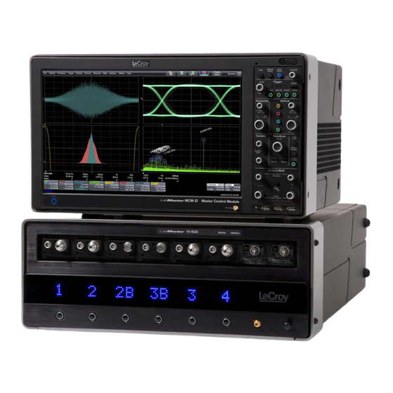
Introducing LabMaster 10 Zi-A Key Specifications Detailed specifications are on the product datasheet at teledynelecroy.com. LabMaster 10 Zi-A real-time oscilloscope systems boast the world’s high- est bandwidth and fastest sampling rate, up to 100 GHz and 240 GS/s. Bandwidth 20 GHz to 100 GHz... - Page 5 Measuring terminals have no rated measurement category (CAT) per IEC/EN 61010-1:2010. regularly. If any part is damaged, cease operation immediately and Measuring terminals are not intended to be connected directly to supply mains. sequester the instrument from inadvertent use. LabMaster 10 Zi-A Getting Started Guide...
-
Page 6: Overview
OVERVIEW Front of MCM Zi-A Master Control Module A. The Touch Screen display is the principal viewing and control center. B. Front Panel release button detaches the front panel for use like a remote. C. The removable Front Panel can be used to control the oscilloscope in addition to the touch screen. -
Page 7: Back Of Mcm Zi-A Master Control Module
LAN connection/remote control (9-pin and 15-pin disabled) F. PCIe 4-Lane DATALINK inputs (2 standard, more with additional acquisition modules) G. DVI-D video out (to external monitor) H. Expansion card slots for optional hardware LabMaster 10 Zi-A Getting Started Guide... -
Page 8: Front Of Lm10Xxzi-A Acquisition Module
OVERVIEW Front of LM10xxZi-A Acquisition Modules G. Two 1.85 mm interfaces are added to the front of 50 GHz through 65 GHz acquisition modules for input of signals > 36 GHz. A. 2.92 mm interfaces (4) D. LED channel indicators show for input of ≤... -
Page 9: Back Of Lm10Xxzi-A Acquisition Module
OVERVIEW Back of LM10xxZi-A Acquisition Modules A. SMA 10 GHz Clock input B. PCIe 1-Lane SYNC input C. PCIe 4-Lane DATALINK output D. AC power inlet with cable clamp LabMaster 10 Zi-A Getting Started Guide... -
Page 10: Front Panel
OVERVIEW Front Panel Most of the front panel controls duplicate functionality available through the touch screen display. They are covered in more detail in the Basics section and in the LabMaster Oscilloscope Systems Operator’s Manual. Below are some special front panel controls. A. -
Page 11: Set Up
See Power on p.3 for power consumption. To avoid an 8. If your system has more than one acquisition module, after power on, overcurrent condition, do not connect two acquisition modules to a run a SystemSkew Cal. See p.24. single circuit. LabMaster 10 Zi-A Getting Started Guide... -
Page 12: Channelsync Configuration
SET UP ChannelSync Configuration The ChannelSync Hub enables you to extend your LabMaster system to PCIe 1-Lane SYNC connection 20 acquisition modules and 80 channels. from control module to hub SMA 10 GHz Clock PCIe 1-Lane SYNC and PCIe 4-Lane DATALINK connections from each acquisition module to hub... -
Page 13: Powering On/Off
CAUTION. Do not change the Windows® Power setting to System Standby or System Hibernate. Doing so may cause failure. See the LabMaster Oscilloscope Systems Operator’s Manual or LabMaster Support for instructions on attaching adapters. LabMaster 10 Zi-A Getting Started Guide... -
Page 14: Connecting To External Devices/Systems
Connect a BNC cable from Aux Out on the front of the The LabMaster 10 Zi-A is preset to accept a DHCP network address over acquisition module to the other device. Go to Utilities > Utilities Setup >... -
Page 15: Basics
Files can also be transferred to a USB drive through any of the host USB ports. Stored user data files are located on the D: drive. LabMaster 10 Zi-A Getting Started Guide... -
Page 16: Using The Touch Screen Display
BASICS Using the Touch Screen Display The entire display is active. Use your finger to touch, drag-and-drop, swipe, pinch, and flick. Many controls that display information also work as “buttons” to access other functions. If you have a mouse installed, you can click anywhere you can touch to activate a control; in fact, you can alternate between clicking and touching, whichever is convenient for you. - Page 17 Related Add a custom name to the trace. dialogs appear as a series of tabs behind the main dialog. Apply a custom label to the trace. LabMaster 10 Zi-A Getting Started Guide...
-
Page 18: Changing The Display
BASICS Changing the Display The grid is 8 Vertical divisions representing 256 Vertical levels and 10 By default, the oscilloscope has the Auto grid mode enabled. Auto adds a Horizontal time divisions. The value represented by each division depends grid for each new trace, up to 16 grids, until no more grids are available. Other on the scale settings of the traces that appear on it. - Page 19 Turn the front panel Intensity knob to control the trace Intensity (the level appears in the Message Bar). Intensity 100% Intensity 15% with Analog Persistence Intensity 15% Intensity 15% with Color Persistence LabMaster 10 Zi-A Getting Started Guide...
-
Page 20: Working With Traces
BASICS Working With Traces Adjusting Setups Trace Descriptor Boxes On setup dialogs, many entries can be made by selecting from the pop-up Channel (C1-Cn), Zoom (Z1-Z12), Math (F1-F12), Memory (M1-M12), and menu that appears when you touch a control. Digital (Digital1-Digital4) descriptor boxes appear along the bottom of the grid area when a trace is turned on. -
Page 21: Maui With Onetouch
To turn on the Measure table when it is closed, touch the Add New box the active trace. and choose Measurement. NOTE: AC1M and DC1M coupling shown in illustrations is not available on LabMasters LabMaster 10 Zi-A Getting Started Guide... - Page 22 BASICS Copy Setups Change Source To copy the setup of one trace to another of the same type (e.g., channel to To change the source of a trace, drag-and-drop the descriptor box of the channel, math to math), drag-and-drop the source descriptor box onto the desired source onto the target descriptor box.
- Page 23 To change the trigger source channel, drag-and-drop the desired channel (Cn) the grid. Cursors on the source traces adjust position accordingly. descriptor box onto the Trigger descriptor box. The trigger will revert to the last trigger set on that channel. LabMaster 10 Zi-A Getting Started Guide...
- Page 24 BASICS Store to Memory Scroll To store a trace to internal memory, drag-and-drop its trace descriptor box To scroll long lists of values or readout tables, swipe the selection dialog or onto the target memory (Mn) descriptor box. table in an up or down direction. Move Trace To move a trace to a different grid, drag-and-drop the trace descriptor box onto the target grid.
- Page 25 Touch the Zn descriptor box to open the zoom factor controls and adjust the zoom exactly. LabMaster 10 Zi-A Getting Started Guide...
-
Page 26: Vertical (Channel)
BASICS Vertical (Channel) Vertical controls adjust traces along the Y axis. Traces represent eight Vertical divisions of the source signal at the selected number of units per division. The zero level is at the center grid line unless you add positive or negative Offset. The Volts knob also controls the Vertical Scale of zoom, math, and memory traces. From the Front Panel Channel Descriptor Box Pre-Processing Summary List... - Page 27 Enter Attenuation for passive and other vendors' probes. Enter Volts/div and Offset. Enter Coupling Apply optional Rescale channel Make any other for cables/probes. Bandwidth Filters. trace, or change Pre-Processing settings. Vertical Unit of grid. LabMaster 10 Zi-A Getting Started Guide...
-
Page 28: Digital
BASICS Digital On instruments equipped with Mixed Signal Solution HDA125, digital selections are added to the Vertical menu, and the front panel Vertical knobs control active Digital line and bus traces. From the Front Panel Digital Descriptor Box # Digital Lines in Group Turn Offset to Digital Sample Rate raise/lower group... - Page 29 Group Height Custom to enter line: high, low, or in divisions. Optionally, enter unique names. transitioning. a custom line name in the field beneath. LabMaster 10 Zi-A Getting Started Guide...
-
Page 30: Horizontal (Timebase)
BASICS BASICS Horizontal (Timebase) Horizontal controls adjust traces along the X axis. Analog traces usually represent one acquisition of the source signal for 10 divisions of the selected Time per division. The trigger event is shown at the center of the grid, unless you add positive or negative Delay time. The front panel Time knob also controls the Horizontal Scale of zoom, math and memory traces, allowing you to "zoom in"... - Page 31 Use DBI dialog to (negative) time before trigger removes Delay. Maximum Points of memory combine channels to or (positive) time after trigger to use in acquisition. increase per channel event to show. sample rate & memory. LabMaster 10 Zi-A Getting Started Guide...
-
Page 32: Triggers
BASICS Trigger Triggers tell the oscilloscope when to perform an acquisition. The acquisition starts as soon as the trigger is armed and all trigger conditions are met, unless postponed by a Holdoff count of time or number of trigger events. Trigger types and modes are described at more length in the LabMaster Oscilloscope Systems Operator’s Manual. - Page 33 Trigger setup dialog. Source channel. Choose trigger Type. Set other conditions, Set trigger Level, Icon summarizes the such as Slope and or Find Level based trigger selections. Coupling (vary by on the input signal. trigger type). LabMaster 10 Zi-A Getting Started Guide...
-
Page 34: Zoom
BASICS Zoom Zoom traces (Zn) display a magnified portion of another trace. Any trace can be zoomed, although Zoom is most useful for channel traces, as it allows you to see the source at the original Timebase at the same time as the Zoom "close up." The Zoom knobs also control the position and scale of Math function traces. From the Front Panel Create Zoom of When you use the front panel Zoom button, a new Zoom trace is created for... - Page 35 Repeat on another section to reposition the Zoom trace. On the source trace setup dialog, touch Action Toolbar Zoom button to create a new zoom of just that source trace. LabMaster 10 Zi-A Getting Started Guide...
-
Page 36: Cursors
BASICS Cursors Cursors set measurement points on the Vertical or Horizontal axis of a trace (or both). The five preset cursor types are described in more detail in the LabMaster Oscilloscope Systems Operator’s Manual. All show the absolute value where the cursor intersects the waveform and the delta of the two lines. From the Touch Screen From the Front Panel Turn to adjust... -
Page 37: Measurements & Statistics
Turn on Help Markers Enter Gates (in div) to constrain plot Histogram, Trend or to show what is being span of measurement, or just drag Track of measurement. measured on waveform. gate markers from edge of grid. LabMaster 10 Zi-A Getting Started Guide... -
Page 38: Math
BASICS Math Math creates a new trace that displays the result of applying a mathematical function (e.g., Sum, Product, FFT) to one or more source traces. Operations can be chained by using one math function as a source for the other. The math trace always opens in a separate grid from the source and can be viewed along side it. -
Page 39: Memories (Reference Waveforms)
Choose Math > Memory Setup. On the Mn tab, select the trace you want stored in Copy From Waveform, then touch Copy Now. Optionally, add Notes or Labels to the stored memory. LabMaster 10 Zi-A Getting Started Guide... -
Page 40: Decode
BASICS Decode If you have installed serial data -TD/TDME options, configuration dialogs are added to the Analysis menu. Decoders apply software algorithms to extract encoded information from physical layer waveforms measured on your oscilloscope. Waveforms are annotated to provide fast, intuitive understanding of the relationship between protocol and signal. -
Page 41: Wavescan
Mode (event to find) and Source trace to scan. Select different views of the scan: event table Take action when an event is found, such as sounding a beep. with/without time stamps, overlay, zoom. LabMaster 10 Zi-A Getting Started Guide... -
Page 42: Maintenance
Dry thoroughly before using. Do not submerge the instrument LabMaster 10 Zi-A incorporates automatic calibration routines so that or allow moisture to penetrate it. it maintains specified performance. Always warm the oscilloscope at CAUTION. -
Page 43: Firmware Updates
MAINTENANCE Firmware Updates Switching Windows Users Free firmware updates are available periodically from the Teledyne LeCroy Windows 10 oscilloscopes are by default set to operate from the LeCroyUser website at teledynelecroy.com/support/softwaredownload. Registered account, but you must run the oscilloscope from the Administrative User, users will receive email notification when a new update is released. -
Page 44: Service
MAINTENANCE Service Service Plans If the LabMaster 10 Zi-A cannot be serviced on location, contact your Extended warranty, calibration, and upgrade plans are available for pur- service center for a Return Material Authorization (RMA) code and chase. Contact your Teledyne LeCroy sales representative or instructions where to ship the product. -
Page 45: Support
MERCHANTABILITY, FITNESS, OR ADEQUACY FOR ANY PARTICULAR PURPOSE OR Help for a demonstration of MAUI with OneTouch. USE. TELEDYNE LECROY SHALL NOT BE LIABLE FOR ANY SPECIAL, INCIDENTAL, OR CONSEQUENTIAL DAMAGES, WHETHER IN CONTRACT OR OTHERWISE. THE Teledyne LeCroy publishes a free Technical Library on its website at CUSTOMER IS RESPONSIBLE FOR THE TRANSPORTATION AND INSURANCE teledynelecroy.com/support/techlib. -
Page 46: Certifications
Certifications 2 Emissions which exceed the levels required by this standard may occur when the system is Teledyne LeCroy certifies compliance to the following standards as of connected to a test object. the time of publication. Please see the EC Declaration of Conformity 3 This product is intended for use in nonresidential areas only. - Page 47 UL Listing Mark: UL 61010-1 Third Edition – Safety standard for electrical measuring and Intellectual Property test equipment. All patents pertaining to the LabMaster 10 Zi-A are on our website at: teledynelecroy.com/patents/ LabMaster 10 Zi-A Getting Started Guide...
- Page 48 933204-00 Rev A, February, 2021 © 2021 Teledyne LeCroy, Inc. All rights reserved.