
Related Manuals for Drive 15230


Summary of Contents for Drive 15230
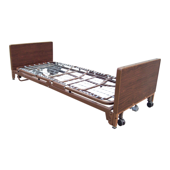
- Page 1 FULL ELECTRIC AND SEMI-ELECRTIC LOW BED Model # 15230 & 15235 user manual READ THESE INSTRUCTIONS BEFORE OPERATING THE DRIVE HOMECARE LOW BED SAVE THESE INSTRUCTIONS FOR FUTURE USE www.drivemedical.com...
-
Page 2: Warning / Caution Summary
WARNING / CAUTION SUMMARY WARNING: KEEP HANDS AND FEET CLEAR OF ALL MOVING PARTS. WARNING: DO NOT ALLOW SMALL CHILDREN ON OR NEAR BED DURING OPERATION WARNING: DO NOT ALLOW THIS DEVICE TO BE OPERATED BY SMALL CHILDREN. WARNING: WHEN OPERATING THE HI/LO, KNEE, OR BACK FUNCTION OF THE BED, ALWAYS ENSURE THAT THE INDIVIDUAL CONFINED TO THE BED IS POSITIONED PROPERLY WITHIN THE CONFINES OF THE BED. DO NOT LET ANY EXTREMITIES PROTRUDE OVER THE SIDE OR BETWEEN THE BED RAILS WHEN PERFORMING ANY FUNCTIONS. CAUTION: DO NOT USE UNAUTHORIZED SIDE RAILS. INSTALL SIDE RAILS PER MANUFACTURER’S INSTRUCTIONS. CAUTION: WARNING/CAUTION LABELS APPLIED TO THE BED OUTLINE HAZARDS OR UNSAFE PRACTICES THAT COULD RESULT IN PERSONAL INJURY AND/OR PROPERTY DAMAGE. CAUTION: PENDANT HAND CONTROL CORD MUST BE ROUTED AND SECURED PROPERLY TO ENSURE THAT CORD DOES NOT BECOME ENTANGLED AND EVENTUALLY SEVERED DURING USE. MAKE SURE ELECTRIC CORDS DO NOT GET TANGLED AROUND THE BED, SIDE RAILS OR LEGS DURING NORMAL OPERATING OF THE BED. CAUTION: WHEN USING NASAL OR MASKED TYPE ADMINISTERING EQUIPMENT, OXYGEN OR AIR TUBING MUST BE ROUTED AND SECURED PROPERLY TO ENSURE THAT TUBING DOES NOT BECOME ENTANGLED AND EVENTUALLY SEVERED DURING NORMAL OPERATION OF BED. CAUTION: BEFORE OPERATING, ENSURE THAT THE BED FRAME RIVETS ARE PROPERLY SEATED IN THE BED END HOOKS: OTHERWISE INJURY OR DAMAGE MAY RESULT. CAUTION: KEEP ALL MOVING PARTS FREE OR OBSTRUCTIONS (I.E. BLANKETS/ SHEETS, HEATING BLANKETS/PADS, TUBING, WIRING, AND OTHER TYPES OF PRODUCTS. - Page 3 ASSEMBLY INSTRUCTIONS HEAD AND FOOT ASSEMBLY Lay the head and foot sections on their sides at approximately right angles to each other with motor clamps up, as shown below. 2. Slide the head and foot sections together until the foot section’s hook catches the head section’s rivet on both sides.
- Page 4 ASSEMBLY INSTRUCTIONS 3. Straighten head and foot and position as shown below. Position head wing as shown below. CAUTION: WHILE BALANCING FRAME, DO NOT ELEVATE KNEE TOO FAR, OR LINKAGE MAY OVER-EXTEND AND LOCK. IF LINKAGE LOCKS, MANUALLY ELEVATE KNEE TO STRAIGHTEN OUT LINKAGE AND PUSH LARGE LINKAGE PLATE TOWARD FOOT OF BED. 4. Attach foot fabric to head fabric: Attach the foot fabric spring clips to the head fabric as shown below. CAUTION: ENSURE THAT HEAD AND FOOT SECTIONS AND SPRING FABRIC ARE ASSEMBLED AS DESCRIBED ABOVE BEFORE CONTINUING WITH BED ASSEMBLY.
-
Page 5: Motor Assembly
ASSEMBLY INSTRUCTIONS MOTOR ASSEMBLY CAUTION: ASSEMBLE MOTOR ON BED AS FOLLOWS; INCORRECT INSTALLATION COULD CAUSE BED TO MOVE IN UNEXPECTED WAYS. MOTOR CAN BE INSTALLED BACKWARDS. NOTE: MOTOR IS EMBOSSED WITH HEAD AND FOOT SYMBOLS (SHOWN AT RIGHT) AT END OF MOTOR. REMOVE MOTOR SIDE CAPS Remove the slide caps from both ends of the motor as shown below. Plungers should be recessed in motor cavities; if not, operate “down” function on the pendant hand control. NOTE: Motor comes from factory with pendant hand control plugged into motor. - Page 6 ASSEMBLY INSTRUCTIONS INSTALL MOTORS 3. Hold the bed securely, positioned with motor cams up, as shown below. 4. Position the motor over both cams. 5. Tap either end of the motor housing (shown below) with enough force to snap the motor assembly into position on the cam. Note: This is a bearing surface requiring a tight fit;...
- Page 7 ASSEMBLY INSTRUCTIONS FULL-ELECTRIC AND SEMI-ELECTRIC BED (ALL MODELS) Standing directly in front of the foot bed end, position it as close to the bed as possible. 2. With one hand, reach over end and lift up bed. 3. Tilt the bed end slightly back toward you. 4.
- Page 8 Plus hi/lo motor into actuator assembly, being careful to route cord with the nylon tie strap provided under fixed base frame cross-angle (as shown below) to ensure clearance with hi/lo drive shaft. The motor plug is located next to the pendant hand control plug on the actuator.
- Page 9 ASSEMBLY INSTRUCTIONS FULL-ELECTRIC AND SEMI-ELECTRIC BED Both ends of the hi/lo rod assembly have a slot to mount on the foot end and head end gearbox shaft pins (see picture at right). Follow steps 2-3 to mount the hi/lo rod assembly on the gearboxes.
- Page 10 OPERATION INSTRUCTIONS CRANK OPERATION (SEMI-ELECTRIC BED ONLY) Use the crank at the center foot of the semi-electric bed to change bed height (raise or lower entire deck).
-
Page 11: Warranty
MAINTENANCE AND SAFETY CHECKS Drive recommends the following maintenance and cleaning procedures be conducted between users and at least once every three (3) years. This form is provided as a guide to help with documentation. ELECTRONICS • Check all controls to make sure all functions work properly. - Page 12 99 Seaview Boulevard Port Washington, NY 11050 Toll Free: 877.224.0946 • 516-998-4600 www.drivemedical.com...