Table of Contents
Advertisement
Quick Links
Advertisement
Table of Contents

Related Manuals for HP EliteBook Folio 1030 G1


Summary of Contents for HP EliteBook Folio 1030 G1
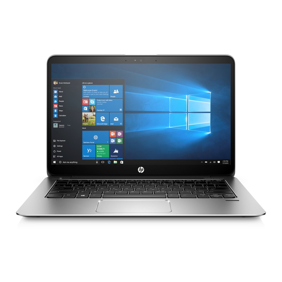
- Page 1 HP EliteBook Folio 1030 G1 Notebook PC Maintenance and Service Guide...
- Page 2 HP Inc. under license. bound by the terms of the HP End User License Not all features are available in all editions of Intel, Celeron, and Pentium are trademarks of Agreement (EULA).
- Page 3 Safety warning notice WARNING! To reduce the possibility of heat-related injuries or of overheating the device, do not place the device directly on your lap or obstruct the device air vents. Use the device only on a hard, flat surface. Do not allow another hard surface, such as an adjoining optional printer, or a soft surface, such as pillows or rugs or clothing, to block airflow.
- Page 4 Safety warning notice...
-
Page 5: Table Of Contents
Table of contents 1 Product description ............................1 2 External component identification ........................4 Display ..................................4 Top ..................................5 TouchPad ............................. 5 Lights ..............................6 Buttons, speakers, and fingerprint reader ..................7 Keys ..............................8 Left ..................................9 Right ..................................10 Bottom ................................. - Page 6 ForcePad (Touchpad) ......................... 47 System board ............................ 48 Speaker assembly ..........................51 6 Computer Setup (BIOS), TPM, and HP Sure Start in Windows 7 ................. 52 Using Computer Setup ............................52 Starting Computer Setup ........................52 Navigating and selecting in Computer Setup ................... 52 Restoring factory settings in Computer Setup .................
- Page 7 Guidelines ............................62 Creating recovery media with HP Recovery Disc Creator ..............62 Creating recovery media ....................63 Backing up your information ......................63 Performing a system recovery ..........................64 Using the Windows recovery tools ....................64 Using f11 recovery tools (select products only) ................65 Using Windows 7 operating system media ..................
- Page 8 viii...
-
Page 9: Product Description
Product description Category Description Product Name HP EliteBook Folio 1030 G1 Notebook PC Processors 6th generation Intel® Core® M processors: ● 6Y75, 1.2-GHz (max turbo frequency 3.1-GHz), 4-MB L3 Cache, 4.5W ● 6Y57, 1.1-GHz (max turbo frequency 2.8-GHz), 4-MB L3 Cache, 4.5W ●... - Page 10 Taps enabled by default Supports 2-way scroll Glass with chemical etched surface Power requirements AC adapters 45-W HP Smart AC adapter 45-W, 2-prong AC adapter 65-W HP Smart AC adapter 65-W Slim AC adapter Power cords 2-wire plug (4.5 mm) (1.0 m)(only available with 45-W 2-prong adapter 3-wire plug with ground pin (4.5 mm) (1.0 m)
- Page 11 Category Description Security Security lock Fingerprint reader Trusted Platform Module (TPM) 1.2/2.0 (Infineon, soldered down) Drive encryption preboot (password, fingerprint, and select smart cards) Preboot authentication (password and fingerprint) Operating system Preinstalled Windows 7 Professional 64 ● Windows 10 Pro 64 ●...
-
Page 12: External Component Identification
Type camera in the taskbar search box, and then select Camera. To use the webcam in Windows 7, select Start > All Programs > Communication and Chat > HP WebCam. WLAN antennas* (2) (select products only) Send and receive wireless signals to communicate with wireless local area networks (WLANs). -
Page 13: Top
Click the question mark icon in the taskbar. Select My PC, select the Specifications tab, and then select User Guides. To access the user guides in Windows 7, select Start > All Programs > HP Help and Support > HP Documentation. TouchPad... -
Page 14: Lights
Lights Component Description Power light ● On: The computer is on. ● Blinking: The computer is in the Sleep state, a power-saving state. The computer shuts off power to the display and other unneeded components. ● Off: The computer is off or in Hibernation. Hibernation is a power-saving state that uses the least amount of power. -
Page 15: Buttons, Speakers, And Fingerprint Reader
Buttons, speakers, and fingerprint reader Component Description Power button When the computer is off, press the button to turn on the ● computer. When the computer is on, press the button briefly to initiate ● Sleep. When the computer is in the Sleep state, press the button ●... -
Page 16: Keys
Component Description Speakers (4) Produce sound. Fingerprint reader Allows a fingerprint logon to Windows, instead of a password logon. Keys Component Description Displays system information when pressed in combination with key. Executes frequently used system functions when pressed in combination with a function key, the num lock key, or the key. -
Page 17: Left
Left Component Description Security cable slot Attaches an optional security cable to the computer. NOTE: The security cable is designed to act as a deterrent, but it may not prevent the computer from being mishandled or stolen. HDMI port Connects an optional video or audio device, such as a high- definition television, any compatible digital or audio component, or a high-speed High Definition Multimedia Interface (HDMI) device. -
Page 18: Right
Click the question mark icon in the taskbar. Select My PC, select the Specifications tab, and then select User Guides. To access the user guides, select Start > All Programs > HP Help and Support > HP Documentation. NOTE: When a device is connected to the jack, the computer speakers are disabled. -
Page 19: Bottom
Component Description ● Blinking amber: The battery has reached a low battery level. When the battery has reached a critical battery level, the battery light begins blinking rapidly. ● Off: The battery is not charging. Power connector Connects an AC adapter. Bottom Component Description... -
Page 20: Service Tag
Service tag When ordering parts or requesting information, provide the computer serial number and model number provided on the service tag. Item Description Function Product name This is the product name affixed to the front of the computer. Serial number (s/n) This is an alphanumeric identifier that is unique to each product. -
Page 21: Illustrated Parts Catalog
Illustrated parts catalog Computer major components Computer major components... - Page 22 Item Component Spare part number Display assembly, touch screen, QHD+ 842280-001 NOTE: Touch displays are only spared as full hinge-ups. Individual components are not spared for touch screen displays. Display assembly, non-touch screen, FHD 850931-001 NOTE: Non-touch displays are only spared as full hinge-ups. Individual components are not spared for non-touch screen displays.
-
Page 23: Bracket Kit
Item Component Spare part number Intel Dual Band Wireless-AC 8260; 802.11ac, 2x2 + Bluetooth 4.2 806721-005 (12) RTC battery (includes double-sided tape) 702853-001 (13) Heat sink/thermal module (includes replacement thermal material): 842301-001 (14) Battery (4-cell, 40-Wh, 2.6-Ah, li ion) 826038-005 (15) Bottom cover 842283-001... -
Page 24: Nfc Cable Kit
NFC Cable Kit Item Component Spare part number NFC Cable Kit 842323-001 NFC cable NFC antenna Chapter 3 Illustrated parts catalog... -
Page 25: Mass Storage Devices
External optical drive (DVD±RW Double Layer Drive) 747080-001 Miscellaneous parts Component Spare part number AC adapter: 45-W HP Smart AC adapter (non-PFC) – non-slim 741727-001 45-W AC adapter (non-PFC), 2-prong 742436-001 65-W HP Smart AC adapter, 4.5 mm, EM 714657-001... - Page 26 Plastics Kit (includes system board clip) 860705-001 Cable, detachable, with tips (4.5 mm and 7.4 mm tips) 736697-001 For use with 65-W HP Smart AC travel adapter, spare part number 693716-001. Docking station cable lock 575921-001 Lock, HP Ultraslim Keyed Cable Lock...
- Page 27 Spare part number HP Comfort Grip wireless mouse 691922-001 HP USB laser mouse 674318-001 Top load case 679921-001 HP professional slim top load case 703888-001 HP business backpack 718548-001 Adapters HDMI to DVI-D adapter 691227-001 Docking connector to ethernet (RJ-45)/VGA...
-
Page 28: Removal And Replacement Procedures Preliminary Requirements
Removal and replacement procedures preliminary requirements Tools required You will need the following tools to complete the removal and replacement procedures: ● Flat-bladed screw driver ● Torx T8 screw driver Phillips P0 and P1 screw drivers ● ● Non-marking pry tool Service considerations The following sections include some of the considerations that you must keep in mind during disassembly and assembly procedures. -
Page 29: Packaging And Transporting Guidelines
An electronic device exposed to ESD may not be affected at all and can work perfectly throughout a normal cycle. Or the device may function normally for a while, then degrade in the internal layers, reducing its life expectancy. CAUTION: To prevent damage to the computer when you are removing or installing internal components, observe these precautions: Keep components in their electrostatic-safe containers until you are ready to install them. -
Page 30: Workstation Guidelines
Workstation guidelines Follow these grounding workstation guidelines: ● Cover the workstation with approved static-shielding material. ● Use a wrist strap connected to a properly grounded work surface and use properly grounded tools and equipment. ● Use conductive field service tools, such as cutters, screw drivers, and vacuums. When fixtures must directly contact dissipative surfaces, use fixtures made only of static-safe materials. - Page 31 Material Voltage protection level Antistatic plastics Bags 1,500 V Carbon-loaded plastic Floor mats 7,500 V Metallized laminate Floor mats 5,000 V Grounding guidelines...
-
Page 32: Removal And Replacement Procedures For Authorized Service Provider Parts
Removal and replacement procedures for Authorized Service Provider parts CAUTION: Components described in this chapter should only be accessed by an authorized service provider. Accessing these parts can damage the computer or void the warranty. Component replacement procedures NOTE: Details about your computer, including model, serial number, product key, and length of warranty, are on the service tag at the bottom of your computer. - Page 33 Pry up on the top (near the display hinge) of the bottom cover to disengage it from the computer. Reverse the removal procedures to install the bottom cover. When replacing the bottom cover, use the following image to determine the correct screw replacement order. Replacing the screws in the correct order makes sure the bottom cover installs evenly on the computer.
- Page 34 Chapter 5 Removal and replacement procedures for Authorized Service Provider parts...
-
Page 35: Keyboard
Keyboard In this section, the first table provides the main spare part number for the keyboard. The second table provides the country codes. Description Spare part number Keyboard (backlit; includes keyboard cable and backlight cable) 842324-xx1 For use in country Spare part For use in country Spare part... - Page 36 Disconnect the battery cable. Remove the keyboard: Remove the Phillips PM2.0×2.0 broadhead screw (1) that secures the keyboard to the computer. Disconnect the keyboard backlight cable from the system board (2). Chapter 5 Removal and replacement procedures for Authorized Service Provider parts...
- Page 37 Disconnect the main keyboard cable from the system board (3). Position the computer on its side and open. Insert a screwdriver or similar thin tool into the screw boss of the screw removed in the previous step, and then press on the back of the keyboard until it disengages from the computer. Component replacement procedures...
- Page 38 Lift the main keyboard cable (1) and the keyboard backlight cable (2) from the slits in the computer, and then remove the keyboard (3). Reverse this procedure to install the keyboard. Chapter 5 Removal and replacement procedures for Authorized Service Provider parts...
-
Page 39: Solid-State Drive
Solid-state drive Description Spare part number Solid-state drive, M.2 512-GB, MLC 842300-001 256-GB, SED, OPAL2 842298-001 256-GB, TLC 842610-001 256-GB, PCIe, NVMe, MLC 842299-001 240-GB, MLC 842611-001 180-GB, MLC 842296-001 180-GB, SED, OPAL2 842297-001 128-GB, TLC 842295-001 Before removing the solid-state drive, follow these steps: Turn off the computer. - Page 40 Disconnect the battery cable. Remove the solid-state drive: Remove the Phillips PM2.0×2.0 screw (1) that secures the drive to the system board. Remove the drive (2) by pulling it away from the connector. NOTE: Solid-state drive drives are designed with notches to prevent incorrect insertion. Reverse this procedure to reassemble and install the solid-state drive.
-
Page 41: Wlan Module
WLAN module Description Spare part number Intel Dual Band Wireless-AC 8260; 802.11ac, 2x2 + Bluetooth 4.2 806721-005 CAUTION: To prevent an unresponsive system, replace the wireless module only with a wireless module authorized for use in the computer by the governmental agency that regulates wireless devices in your country or region. - Page 42 NOTE: The WLAN antenna cable labeled “1” connects to the WLAN module “Main” terminal labeled “1”. The WLAN antenna cable labeled “2” connects to the WLAN module “Aux” terminal labeled “2”. If the computer is equipped with an 802.11a/b/g/n WLAN module, the yellow WLAN antenna cable connects to the middle terminal on the WLAN module.
-
Page 43: Display Assembly
Display assembly This section describes removing components that require you to completely remove the display panel. You can remove the display bezel, webcam, and display panel without removing the entire display hinge-up from the computer. Before removing the display assembly, follow these steps: Turn off the computer. - Page 44 Remove the two Phillips PM2.5×4.0 screws (2) that secure the bracket on the left side of the computer, and the remove the bracket (3). The display brackets are available in the Bracket Kit using spare part number 842302-001. To remove the right display bracket, remove the Phillips PM2.0×2.0 screw (1) that secures the display bracket to the right side of the computer, and then remove the bracket (2).
- Page 45 Disconnect the antennas from the WLAN module (2). Remove the WLAN antenna from the clips and routing path built into the computer (3). Disconnect the webcam cable from the system board (4). Remove the four Phillips PM2.5×4.0 screws (1) that secure the display to the computer. Open the computer so the display is at an approximate 90 degree angle (2).
- Page 46 Remove the computer from the display assembly (3). Reverse this procedure to reassemble and install the display assembly. Chapter 5 Removal and replacement procedures for Authorized Service Provider parts...
-
Page 47: Rtc Battery
RTC battery Description Spare part number RTC battery (includes double-sided tape) 702853-001 Before removing the RTC battery, follow these steps: Turn off the computer. If you are unsure whether the computer is off or in Hibernation, turn the computer on, and then shut it down through the operating system. Disconnect the power from the computer by unplugging the power cord from the computer. - Page 48 Detach the RTC battery (2) from the computer. Reverse this procedure to install the RTC battery. Chapter 5 Removal and replacement procedures for Authorized Service Provider parts...
-
Page 49: Heat Sink
Heat sink NOTE: The heat sink assembly spare part kit includes replacement thermal material. Description Spare part number Heat sink assembly 842301-001 Before removing the heat sink, follow these steps: Turn off the computer. If you are unsure whether the computer is off or in Hibernation, turn the computer on, and then shut it down through the operating system. - Page 50 Remove the heat sink (2). CAUTION: Take extreme care when removing the heat sink. The heatpipe is very fragile and can be easily damaged and bent during removal. NOTE: The thermal material must be thoroughly cleaned from the surfaces of the heat sink and the system board components each time the heat sink is removed.
-
Page 51: Battery
Battery Description Spare part number 4-cell, 40-Wh, 2.6-Ah, Li ion battery 826038-005 Before disassembling the computer, follow these steps: Turn off the computer. If you are unsure whether the computer is off or in Hibernation, turn the computer on, and then shut it down through the operating system. Disconnect the power from the computer by unplugging the power cord from the computer. - Page 52 Lift the battery out of the computer (2). Chapter 5 Removal and replacement procedures for Authorized Service Provider parts...
-
Page 53: Fingerprint Reader Board
Fingerprint reader board Description Spare part number Fingerprint reader board (includes cable) 790074-001 Before removing the fingerprint reader board, follow these steps: Turn off the computer. If you are unsure whether the computer is off or in Hibernation, turn the computer on, and then shut it down through the operating system. -
Page 54: Nfc Module
NFC module Description Spare part number NFC (Near Field Communication) module 790069-001 NFC cable kit (includes NFC cable and antenna) 842323-001 Before removing the NFC module, follow these steps: Turn off the computer. If you are unsure whether the computer is off or in Hibernation, turn the computer on, and then shut it down through the operating system. -
Page 55: Forcepad (Touchpad)
ForcePad (Touchpad) Description Spare part number ForcePad 842287-001 Cable Kit 842293-001 Before removing the ForcePad, follow these steps: Turn off the computer. If you are unsure whether the computer is off or in Hibernation, turn the computer on, and then shut it down through the operating system. Disconnect the power from the computer by unplugging the power cord from the computer. -
Page 56: System Board
System board NOTE: The system board spare part kit includes replacement thermal material. All system boards use the following part numbers: xxxxxx-001: Windows 7 or non-Windows operating systems xxxxxx-601: Windows 10 operating system Description Spare part number System board equipped with Intel Core M7-6Y75 processor 842326-xxx System board equipped with Intel Core M5-6Y57 processor 842328-xxx... - Page 57 (10): RTC battery Remove the WLAN antenna from the routing channel on the system board (1). Remove the seven Phillips PM2.0×4.0 screws (2) that secure the system board to the computer. Lift the right side of the system board up at an angle (1). CAUTION: To avoid damaging or breaking the system board, use two hands when removing the board.
- Page 58 Pull the system board away from and out of the computer (2), making sure the connectors on the side of the board are clear of the computer. Reverse this procedure to install the system board. Chapter 5 Removal and replacement procedures for Authorized Service Provider parts...
-
Page 59: Speaker Assembly
Speaker assembly Description Spare part number Speaker assembly (includes cable) 837352-001 Before removing the speaker assembly, follow these steps: Turn off the computer. If you are unsure whether the computer is off or in Hibernation, turn the computer on, and then shut it down through the operating system. Disconnect the power from the computer by unplugging the power cord from the computer. -
Page 60: Computer Setup (Bios), Tpm, And Hp Sure Start In Windows 7
To start Computer Setup, follow these steps: Start Computer Setup. ▲ ● Computers or tablets with keyboards: ▲ Turn on or restart the computer, and when the HP logo appears, press to enter Computer Setup. ● Tablets without keyboards: ▲... -
Page 61: Restoring Factory Settings In Computer Setup
Updating the BIOS Updated versions of the BIOS may be available on the HP website. Most BIOS updates on the HP website are packaged in compressed files called SoftPaqs. Some download packages contain a file named Readme.txt, which contains information regarding installing and troubleshooting the file. -
Page 62: Downloading A Bios Update
Do not shut down the computer or initiate Sleep. Do not insert, remove, connect, or disconnect any device, cable, or cord. Access Help and Support by selecting Start > All Programs > HP Help and Support > HP Support Assistant. -
Page 63: Changing The Boot Order Using The F9 Prompt
BIOS to its previously safe state, without user intervention. HP Sure Start is configured and already enabled so that most users can use the HP Sure Start default configuration. The default configuration can be customized by advanced users. -
Page 64: Computer Setup (Bios), Tpm, And Hp Sure Start In Windows 10
To start Computer Setup, follow these steps: Start Computer Setup. ▲ ● Computers or tablets with keyboards: ▲ Turn on or restart the computer, and when the HP logo appears, press to enter Computer Setup. ● Tablets without keyboards: ▲... -
Page 65: Restoring Factory Settings In Computer Setup
Updating the BIOS Updated versions of the BIOS may be available on the HP website. Most BIOS updates on the HP website are packaged in compressed files called SoftPaqs. Some download packages contain a file named Readme.txt, which contains information regarding installing and troubleshooting the file. -
Page 66: Downloading A Bios Update
Do not shut down the computer or initiate Sleep. Do not insert, remove, connect, or disconnect any device, cable, or cord. Type support in the taskbar search box, and then select the HP Support Assistant app. – or – Select the question mark icon in the taskbar. -
Page 67: Changing The Boot Order Using The F9 Prompt
BIOS to its previously safe state, without user intervention. HP Sure Start is configured and already enabled so that most users can use the HP Sure Start default configuration. The default configuration can be customized by advanced users. -
Page 68: Using Hp Pc Hardware Diagnostics (Uefi)
Using HP PC Hardware Diagnostics (UEFI) HP PC Hardware Diagnostics is a Unified Extensible Firmware Interface (UEFI) that allows you to run diagnostic tests to determine whether the computer hardware is functioning properly. The tool runs outside the operating system so that it can isolate hardware failures from issues that are caused by the operating system or other software components. - Page 69 Use the categories listed to find your product. – or – Click Find Now to let HP automatically detect your product. Select your computer, and then select your operating system. In the Diagnostic section, follow the on-screen instructions to select and download the UEFI version you want.
-
Page 70: Backup And Recovery In Windows 7
Backup and recovery in Windows 7 Your computer includes HP and Windows tools to help you safeguard your information and retrieve it if you ever need to. These tools will help you return your computer to a proper working state, all with simple steps. -
Page 71: Creating Recovery Media
HP Recovery Disc Creator can create two kinds of recovery DVDs: ● Windows 7 operating system DVD—Installs the operating system without additional drivers or applications. Driver Recovery DVD—Installs specific drivers and applications only, in the same way that the HP ●... -
Page 72: Performing A System Recovery
To create a backup using Windows Backup and Restore: NOTE: The backup process may take over an hour, depending on file size and the speed of the computer. Select Start > All Programs > Maintenance > Backup and Restore. Follow the on-screen instructions to set up your backup, create a system image (select products only), or create system repair media (select products only). -
Page 73: Using F11 Recovery Tools (Select Products Only)
Windows 7 operating system DVD to reboot the computer and repair the operating system. To order a Windows 7 operating system DVD, go to the HP website. For U.S. support, go to http://www.hp.com/support. For worldwide support, go to http://welcome.hp.com/country/us/en/... - Page 74 NOTE: This process takes several minutes. If possible, back up all personal files. Restart the computer, and then insert the Windows 7 operating system DVD into the optical drive before the Windows operating system loads. When prompted, press any keyboard key. Follow the on-screen instructions.
-
Page 75: 10 Backup And Recovery In Windows 10
Use HP Recovery Manager to create HP Recovery media after you successfully set up the computer. This step creates a backup of the HP Recovery partition on the computer. The backup can be used to reinstall the original operating system in cases where the hard drive is corrupted or has been replaced. For... -
Page 76: Using Windows Tools
HP Recovery media can also be used to customize the system or restore the factory image if you replace the hard drive. -
Page 77: Restore And Recovery
Creating HP Recovery media (select products only) on page If your computer does not allow the creation of HP Recovery media or if the HP Recovery media does not ● work, you can obtain recovery media for your system from support. See the Worldwide Telephone Numbers booklet included with the computer. -
Page 78: Using The Hp Recovery Partition (Select Products Only)
Using HP Recovery media to recover You can use HP Recovery media to recover the original system. This method can be used if your system does not have an HP Recovery partition or if the hard drive is not working properly. -
Page 79: Changing The Computer Boot Order
Changing the computer boot order If your computer does not restart in HP Recovery Manager, you can change the computer boot order, which is the order of devices listed in BIOS where the computer looks for startup information. You can change the selection to an optical drive or a USB flash drive. -
Page 80: 11 Specifications
11 Specifications Computer specifications Metric U.S. Dimensions Width 31.0 cm 12.2 in Depth 21.0 cm 8.27 in Height 1.57 cm 0.62 in Weight FHD (no touch), 8 GB,M.2 128 GB SSD, fingerprint reader, 1.20 kg 2.64 lbs camera, no NFC, WLAN QHD+ (with touch), 8 GB, M.2 128 GB SSD, fingerprint reader, 1.21 kg 2.67 lbs... -
Page 81: 33.78-Cm (13.3-In) Display Specifications
33.78-cm (13.3-in) display specifications Metric U.S. Dimensions Height 17.0 cm 6.69 in Width 29.0 cm 11.42 in Diagonal 33.78 cm 13.3 in Brightness 300 nits Resolution 1920 × 1080 3200 × 1800 QHD+ Viewing angle UWVA Backlight WLED Graphics adapter eDP 1.3 Thickness 3.0 mm... -
Page 82: M.2 Solid-State Drive Specifications
M.2 solid-state drive specifications 128-GB* 180-GB* 240-GB* 256-GB* 512-GB* Dimensions Height 1 mm 1 mm 1 mm 1 mm 1 mm Length 50.8 mm 50.8 mm 50.8 mm 50.8 mm 50.8 mm Width 28.9 mm 28.9 mm 28.9 mm 28.9 mm 28.9 mm Weight <... -
Page 83: 12 Statement Of Memory Volatility
Following system shutdown and removal of all power sources from an HP Business PC system, personal data can remain on volatile system memory (DIMMs) for a finite period of time and will also remain in nonvolatile memory. - Page 84 If a DriveLock password is set, select the Security menu, and scroll down to Hard Drive Utilities under the Utilities menu. Select Hard Drive Utilities, select DriveLock, then uncheck the checkbox for DriveLock password on restart. Select OK to proceed. Select the Main menu, and then select Reset BIOS Security to factory default.
- Page 85 NOTE: If the system has a BIOS administrator password, enter the password at the prompt. Select Main, select Restore Defaults, and then select Yes to load defaults. Select the Security menu, select Restore Security Level Defaults, and then select Yes to restore security level defaults.
- Page 86 NOTE: The amount of time it takes for Disk Sanitizer to run can take several hours. Plug the computer into an AC outlet before starting. Turn on or restart the computer, and then press while the "Press the ESC key for Startup Menu" message is displayed at the bottom of the screen.
-
Page 87: Nonvolatile Memory Usage
HP Sure Start only) backup of The content is managed Embedded Controller. critical System solely by the HP Sure Start BIOS code, EC Embedded Controller. firmware, and critical PC configuration data for select... - Page 88 Fingerprint reader 512 KByte flash Stores Fingerprint reader memory is Only a digitally signed fingerprint programmed by user application can make the templates. enrollment in HP call to write to the flash. ProtectTools Security Manager. Chapter 12 Statement of memory volatility...
-
Page 89: Questions And Answers
HP has provided options in Computer Setup (BIOS) to allow you to run in legacy BIOS, if required by the operating system. Examples of this requirement would be if you upgrade or downgrade the OS. -
Page 90: Using Hp Sure Start (Select Models Only)
BIOS to its previously safe state, without user intervention. Those select computer models ship with HP Sure Start configured and enabled. HP Sure Start is configured and already enabled so that most users can use the HP Sure Start default configuration. The default configuration can be customized by advanced users. -
Page 91: 13 Power Cord Set Requirements
13 Power cord set requirements The wide-range input feature of the computer permits it to operate from any line voltage from 100 to 120 volts AC, or from 220 to 240 volts AC. The 3-conductor power cord set included with the computer meets the requirements for use in the country or region where the equipment is purchased. - Page 92 Country/region Accredited agency Applicable note number Sweden SEMKO Switzerland Taiwan BSMI The United Kingdom The United States The flexible cord must be Type HO5VV-F, 3-conductor, 1.0-mm² conductor size. Power cord set fittings (appliance coupler and wall plug) must bear the certification mark of the agency responsible for evaluation in the country or region where it will be used. The flexible cord must be Type SPT-3 or equivalent, No.
-
Page 93: 14 Recycling
Follow the local laws and regulations in your area for battery disposal. HP encourages customers to recycle used electronic hardware, HP original print cartridges, and rechargeable batteries. For more information about recycling programs, see the HP Web site at http://www.hp.com/recycle. -
Page 94: Index
HP PC Hardware Diagnostics (UEFI) downloading an update 54, 58 identifying 11 using 60 updating 53, 57 Driver Recovery DVD, HP Recovery Disc Creator, using 62 boot order creating 62 HP Recovery Manager changing 71 using for restore 65 correcting boot problems 71... - Page 95 68 ports wireless 6 system 69 HDMI 9 USB flash drive 70 product description 2 using HP Recovery media 68 M.2 solid-state drive USB 3.0 charging (powered) 9, recovery media specifications 74 creating 67 mass storage device USB Type-C (charging) 9...
- Page 96 security, product description 3 transporting guidelines 21 service considerations cables 20 USB 3.0 charging (powered), connectors 20 identifying 9, 10 plastic parts 20 USB legacy support 52, 56 service tag 12 USB Type-C (charging) port, serviceability, product description 3 identifying 9 setup utility navigating and selecting 52, 56 restoring factory settings 53, 57...