Elkay EZ Series Installation, Care & Use Manual
Bottle filling stations & coolers
Hide thumbs
Also See for EZ Series:
- Installation, care & use manual (18 pages) ,
- Installation & use manual (10 pages) ,
- Installation & use manual (10 pages)
Table of Contents
Advertisement
Quick Links
EZSTLG8WS*1A,
LZSTLG8WS*1A
INSTALLATION, CARE & USE MANUAL
Manual de Instalación, Cuidado y Utilización
Manuel d'installation/entretien/utilisation
EZ & LZ
Series Bottle Filling Stations & Coolers
TM
TM
EZ & LZ
Serie Botella Bombas y Enfriadores
TM
TM
EZ & LZ
Stations de Remplissage de Bouteille Série et Refroidisseurs
TM
TM
Page 1
0000000740 (Rev. B - 8/13)
Advertisement
Table of Contents

Related Manuals for Elkay EZ Series


Summary of Contents for Elkay EZ Series
- Page 1 EZSTLG8WS*1A, LZSTLG8WS*1A INSTALLATION, CARE & USE MANUAL Manual de Instalación, Cuidado y Utilización Manuel d’installation/entretien/utilisation EZ & LZ Series Bottle Filling Stations & Coolers EZ & LZ Serie Botella Bombas y Enfriadores EZ & LZ Stations de Remplissage de Bouteille Série et Refroidisseurs Page 1 0000000740 (Rev.
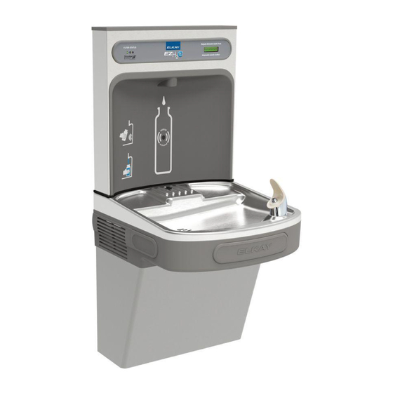
- Page 2 EZSTLG8WS*1A, LZSTLG8WS*1A Pictured is unit only without bottle filler. Uses HFC-134A refrigerant Usa refrigerante HFC-134A Utilise du fluide frigorigéne HFC-134A See Fig. 10 See Fig. 10 7, 16, 18, 24 Fig. 1 0000000740 (Rev. B - 8/13) Page 2...
- Page 3 EZSTLG8WS*1A, LZSTLG8WS*1A Fig. 2 Page 3 0000000740 (Rev. B - 8/13)
- Page 4 EZSTLG8WS*1A, LZSTLG8WS*1A Fig. 3 0000000740 (Rev. B - 8/13) Page 4...
-
Page 5: Entretien
EZSTLG8WS*1A, LZSTLG8WS*1A HANGER BRACKETS & TRAP INSTALACIÓN DE LOS SOPORTES INSTALLATION DES SUPPORTS FIJADORES Y EL PURGADOR DE SUSPENSION ET DU SIPHON INSTALLATION Retire el soporte fijador que se encuentra 1) Retirez le support de suspension fixé au dos du 1) Remove hanger brackets fastened to back of conectado a la parte posterior del enfriador refroidisseur en retirant une (1) vis. - Page 6 EZSTLG8WS*1A, LZSTLG8WS*1A Service Instructions Lower and Upper Shroud To access the refrigeration system and plumbing connections, remove four screws from bottom of cooler to remove the lower shroud. To remove the upper shroud for access to the pushbars, regulator, solenoid valve or other components located in the top of the unit, remove lower shroud, disconnect drain, remove four screws from tabs along lower edge of upper shroud, unplug two wires and water tube.
- Page 7 EZSTLG8WS*1A, LZSTLG8WS*1A 7/16” BOLT HOLES FOR MOUNTING FASTENING UNIT TO WALL TOP COVER SCREWS UNIT CENTER LINE Fig. 5 Fig. 6 BOTTLE FILLER INSTALLATION 1) Remove two (2) mounting screws with 5/32” allen wrench holding top cover to Bottle Filler (See FIG. 6). Remove top cover. Note do not discard mounting screws, they will be needed to reinstall top cover.
- Page 8 EZSTLG8WS*1A, LZSTLG8WS*1A BF11 PROGRAM SETTING THE CONTROL BOARD VERIFY CONTROL BOARD SOFTWARE Continued from below: 1) To verify the software program of the control board the unit will 2) When the display changes to “SETTINGS”, depress the button again. need to be shut down and restarted. The chiller (if present) does The display will change to show not need to be shut down and restarted.
- Page 9 EZSTLG8WS*1A, LZSTLG8WS*1A Drain Cover Drain Mat Screws DRAIN MAT EXPLODED VIEW Fig. 9 WALL MOUNTING PLATE DRAIN MAT ASSEMBLY AND CARE 1) Place Drain Cover on mat and install the four screws as shown in Fig. 9. 2) It is recommended that the cover be removed and the drain cover be cleaned weekly.
-
Page 10: Cleaning The Strainer
EZSTLG8WS*1A, LZSTLG8WS*1A NOTE: When installing replacement bubbler and pedestal, tighten nut only to hold parts snug in position. Do Not Overtighten. NOTA: Al instalar el grifo y pedestal de reemplazo, apriete la tuerca unicamente para mantener las piezas en una Basin posicion adjustada. - Page 11 EZSTLG8WS*1A, LZSTLG8WS*1A Fig. 15 WATERSENTRY Filter Detail ® Detalle WATERSENTRY Filtro ® Description WATERSENTRY Filtrage ® WATERSENTRY ® FILTER PARTS LIST LISTA DE PIEZAS DEL FIL- LISTE DES PIÈCES DU (See Fig. 15) TRO (Vea la Fig. 15) FILTRE (Voir Fig. 15) ITEM NO.
-
Page 12: Switch Activation
EZSTLG8WS*1A, LZSTLG8WS*1A Switch Activation Note: Only side push activation is shown. Front push works the same. Detalle de la activación del interruptor ó Nota: Lateral presion activaci n que se muestran. Frontal presion es la similar. Description de l’activation de l’interrupteur Remarque: Laterel puossoir activaci ó... - Page 13 POUR OBTENIR DES PIÈCES, CONTACTEZ VOTRE DISTRIBUTEUR LOCAL OU COMPOSEZ LE 1.800.323.0620 PRINTED IN U.S.A. IMPRESO EN LOS E.E.U.U. ELKAY MANUFACTURING COMPANY • 2222 CAMDEN COURT • OAK BROOK, IL 60523 • 630.574.8484 IMPRIMÉ AUX É.-U. Page 13 0000000740 (Rev. B - 8/13)