Dyson pure cool Service Manual
Hide thumbs
Also See for pure cool:
- Operating instructions manual (100 pages) ,
- Operating manual (56 pages) ,
- User manual (36 pages)
Advertisement
Advertisement
Table of Contents

Related Manuals for Dyson pure cool


Summary of Contents for Dyson pure cool
- Page 1 Service manual Issued March 18...
-
Page 2: Table Of Contents
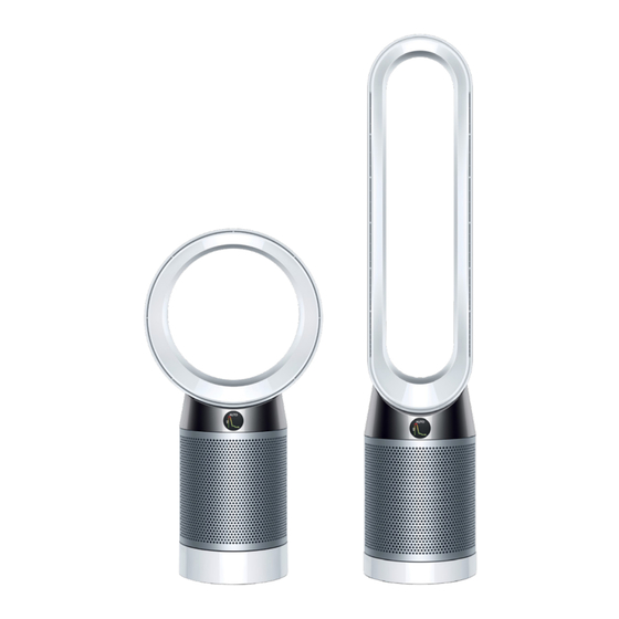
Contents This manual is written specifically for Dyson trained engineers and covers the full TP04 and DP04 range. The service instructions assume that the engineer has the approved tools and test equipment with them. Product overview Features and benefits....................01 Technical information Electrical safety testing....................03... -
Page 3: Product Overview Features And Benefits
Product overview Features and benefits Sealed filtration - removes gases and particles The fully - sealed filter system combines an activated carbon filter to remove gases, and a Glass HEPA filter that captures 99.97% of microscopic allergens and pollutants as small as 0.3 microns. Draft-free diffused mode New side vent to diffuse purified air, creating circulation with no draft. - Page 4 Maximise personal comfort by clean air. customising the oscillation range up to 350˚ through the App or choose from 4 standard oscillation settings from 45˚ to 350˚. Dyson Link app Intelligent purification. Responds and reports to your Dyson Link app.
-
Page 5: Technical Information
These tests are vital to avoid any possibility to and upon completion of all repairs to of personal injury to the end user. Dyson floorcare products and before any functional checks. The socket and see PDIT 360 You must ensure that a full visual inspection (or equivalent) should be used to test of the product is completed prior to repair. -
Page 6: Wiring Diagram
Technical infomation Wiring diagram Assembly Power Adapter Main Main Motor Receiver Plantower Sensor Dust Sensor Lower Body Oscillation Assembly Oscillation Motor Sensor... -
Page 7: Aq Displays During Calibration
Technical infomation AQ displays during calibration Prior to carrying out any repairs that are associated to fauly air quality readings, it is important to determine whether the product has a genuine fault or is simply calibrating. When the product is new, the AQ sensors begin calibrating. This 1 hour process will affect the VOC &... -
Page 8: Accessing The Diagnostic Menu
Technical infomation Accessing the diagnostic menu Diagnostic menu Built into DP04 and TP04’s software there is an engineers diagnostic menu designed to enable the repair agent a quick diagnosis of the machines failure. The menu is accessed by pressing a sequence of buttons via a standard remote control. AUTO AUTO AUTO... -
Page 9: Diagnostic Table
2. Temp Sensor fault 3. Humidity Sensor fault 4. AQ Sensor fault 5. Wrong Power Supply Unit (PSU) inserted/PSU fault, advise to use the Dyson PSU that came with the machine. 6. Fault. Shown permanently if fatal fault. Shown temporarily if limited... -
Page 10: Repair Notes
Repair notes General information Important: this product contains a WiFi PCB that stores critical data. If a WiFi PCB requires replacement the data will require reinstalling following the repair. The necessary equipment is not currently available, therefore any machines requiring a WiFi PCB replacement cannot be repaired until further notice. -
Page 11: Full Dismantle
Repair notes Full dismantle 01 Press the left and right filter release buttons on either side of the product. 02 Remove the two shrouds and HEPA filters. 03 Remove the two Carbon filters. - Page 12 04 Turn the machine upside down. Remove the four 16mm T-10 screws from the front and rear of the machine holding the Amp assembly to the Main body. 05 Carefully lift the Amp assembly from the Main body. Note: the Amp will still be connected by the Flow motor loom.
- Page 13 Note: the LCD display is secured with a locking mechanism that will need to be opened before removing/replacing. LCD display Main PCB Wifi PCB Dust sensor Sensor satelite* Temperature/ Humidity sensor VOC sensor* 06 This diagram is to identify all PCB’s within the main body. If the reason for the repair is to replace any of the PCB’s or sensors this can be done at this point.
- Page 14 07 Remove the motor to AMP seal. 08 Disconnect the Motor loom from the Main PCB assembly. 09 Release the Motor loom grommet from the main body and guide the connector through the hole.
- Page 15 10 Carefully release the three Motor bucket catches from around the main body. 11 Carefully lift the Motor and bucket assembly out of the main body. For Motor and bucket fitting instructions go page 24 step 39. If the reason for the repair is to replace the Lower body assembly proceed to the next step.
- Page 16 12 Remove the two 7mm T-8 screws holding the right handside filter catch assembly. 13 Lift the Filter catch assembly up and away from the Main body. 14 Disconnect the Oscillation and Main power connectors from the Main PCB. For ease, first disconnect the Sensor input harness assembly.
- Page 17 15 Carefully release the two looms from the retainers and the channel in the side of the main body. 16 Remove the five 12mm T-15 screws from the inside of the main body. 17 Lift the main body away from the Oscillation housing.
- Page 18 18 Disconnect the Oscillation motor control harness from the Oscillation motor. 19 Disconnect the IR sensor loom from the IR sensor. 20 Open the grommet clip.
- Page 19 21 Release the grommets from the grommet clip. 22 Release the Grommets from the retainer.
-
Page 20: Full Rebuild
Repair notes Full rebuild 23 Connect the new Oscillation motor control harness to the IR sensor. 24 Connect the harness to the Oscillation motor. 25 Locate the first two grommets together and locate into the grommet clip. - Page 21 26 Close the grommet clip. 27 Locate the second two grommets together into the retainers. 28 Ensure the two looms are located where shown.
- Page 22 29 Loacte the Main body onto the Lower body ensuring the two looms are located within the channel. 30 Fit the six 7mm T-15 screws. 31 Ensure the looms are retained within the channel.
- Page 23 32 Ensure the looms are retained securely all the way up the channel. 33 Locate the bottom of the Filter catch assembly into the bottom of the channel in the Main body. 34 Ensure the hook details on the main body are located within the holes in the Filter catch assembly.
- Page 24 35 Fit the two 7mm T-8 screws. 36 Connect and dress the Oscillation Motor control harness to the Main PCB as shown. 37 Connect and dress the Main power loom to the Main PCB as shown.
- Page 25 38 Connect and dress the VOC and Dust sensor loom to the Main PCB as shown.
- Page 26 Cross section view of Upper retention ring and spring positions Important: during shipping/transport the Upper, Lower retention rings and springs can detach. Before fitting the Motor and bucket assembly the Upper and Lower Spring retention rings have to be seated on their corresponding ledges on the motor bucket and the six springs attached as shown.
- Page 27 40 When fitting a new Motor and bucket assembly the old (or a new) impeller inlet shroud will need to be fitted. Line up the three hooks around the inlet shroud with the three holes around the Motor and Bucket assembly.
- Page 28 41 Line up the detail on the side of the Motor and bucket service assembly with the groove on the inside of the Main body.
- Page 29 42 Carefully lower the Motor and Bucket assembly into the Main body. 43 Feed The Motor loom connector through the hole in the Main body. 44 Ensure the motor loom grommet is orientated and seated correctly into the Main body.
- Page 30 45 Push down firmly on the top of the Motor bucket service assembly until the three catches around the motor bucket have securely clipped into the Main body. Note: the Tension springs and Upper and Lower retention rings can come disconnected during this process.
- Page 31 46 Connect the motor loom to the Main PCB. 47 Fit the Motor to Amp seal, ensuring it is seated correctly around the Motor. 48 Connect the Flow motor loom to the Main PCB. Dress the Flow motor loom into the retainer provided around the Main body.
- Page 32 49 Locate the Amp assembly onto the Main body, ensuring the Amp is facing the correct way. 50 Fit the four 16mm T-10 screws to the front and rear of the product. 51 Loacte the two carbon filters ensuring they click into position.
- Page 33 52 Locate the two shrouds.
-
Page 34: Parts Diagram Main Body Assembly
Parts diagram Main body assembly Motor Bucket Seal Tension Spring Motor Bucket Service Assy Impeller Inlet Shroud Kapton Tape LCD Display Service Assy Sensor Input Harness Assy Main PCB Assy Sensor PCB Service Assy Wifi Harness Assy Dust Sensor Screw M3.5x12-T15 Service Assy Screw M3x16-T10 Screw (M2.5x7-T8) -
Page 35: Amp Assembly
Parts diagram Amp assembly Remote Control Assy Screw M3.0x15-P1 On/Off Button Service Assy Air Amp Neck Service Assy Amp Assy Filter Shroud Glass Hepa Filter MO Amp Assy Carbon Filter Assy MO...