Teledyne Lecroy HDO4000A Getting Started Manual
High definition oscilloscopes
Hide thumbs
Also See for HDO4000A:
- Operator's manual (154 pages) ,
- Quick start manual (2 pages) ,
- Getting started manual (48 pages)
Table of Contents
Advertisement
Quick Links
Advertisement
Table of Contents

Related Manuals for Teledyne Lecroy HDO4000A


Summary of Contents for Teledyne Lecroy HDO4000A
- Page 1 HDO4000A High Definition Oscilloscopes Getting Started Guide...
- Page 3 However, clients are encouraged to duplicate and distribute Teledyne LeCroy documentation for internal educational purposes. HDO and Teledyne LeCroy are trademarks of Teledyne LeCroy, Inc. Windows is a registered trademark of Microsoft Corporation. Other product or brand names are trademarks or requested trademarks of their respective holders.
-
Page 4: Table Of Contents
Welcome Thank you for buying a Teledyne LeCroy product. We’re certain you’ll be pleased with the detailed features unique to our instruments. This Getting Started Guide is designed to cover important safety and installation information for your oscilloscope, along with some basic operating procedures so you’re quickly working with waveforms. - Page 5 INTRODUCTION HDO4000A High Definition Oscilloscopes...
-
Page 6: Introduction
Waveforms captured and displayed and Find allows you to search a single acquisition using more than 20 on the HDO4000A with HD4096 technology are cleaner and crisper. Signal different criteria. History Mode lets you scroll back in time to view previous details often lost in the noise are clearly visible and easy to distinguish, acquisitions and isolate anomalies. -
Page 7: Specifications
• Sample Rate up to 10 GS/s * 1 Oscilloscope Registration Card • 1 Calibration Document Memory up to 12.5 Mpts/ch HDO4000A-MS models include: Digital Channels • Digital Sample Rate 1.25 GS/s 1 digital leadset • 5 flying ground leads Min. -
Page 8: General Safety Information
INTRODUCTION General Safety Information Precautions • Use proper power cord. Use only the power cord shipped with this This section contains instructions that must be observed to keep the instrument and certified for the country of use. instrument operating in a correct and safe condition. You are required to follow generally accepted safety procedures in addition to the precautions •... - Page 9 HDO4000A will meet all specifications. Power and Grounding Warm up the HDO4000A for at least 20 minutes prior to use. During the The instrument operates from a single-phase, 100 to 240 Vrms (± 10%) warm-up period, the oscilloscope will automatically initiate calibrations to AC power source at 50/60/400 Hz (±...
-
Page 10: Support
Teledyne LeCroy publishes a free Technical Library on its website. Manuals, tutorials, application notes, white papers, and videos are available to help you get the most out of your Teledyne LeCroy products. The HDO4000A Oscilloscopes Operator’s Manual can be downloaded from teledynelecroy.com/support/techlib under Manuals >... - Page 11 SET UP HDO4000A High Definition Oscilloscopes...
-
Page 12: Set Up
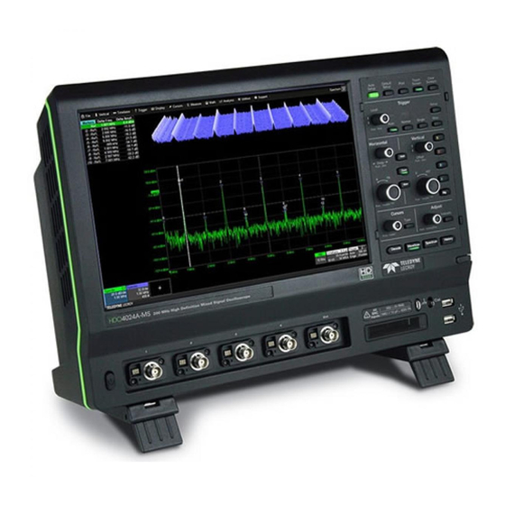
SET UP The Front of Your Oscilloscope Touch Screen Display Front Panel Built-in Stylus Holder Power Button Channel Inputs EXT Input Mixed Signal Interface Ground and Calibration Output Terminals USB Ports Rotating/Tilting Feet... - Page 13 HDO4000A oscilloscopes are compatible with the push the connector included passive probes and all Teledyne LeCroy ProBus active probes into the mixed signal that are rated for the oscilloscope’s bandwidth. Probe specifications and interface until you hear documentation are available at teledynelecroy.com/probes.
-
Page 14: The Side Of Your Oscilloscope
SET UP The Side of Your Oscilloscope Video Output VGA, DVI, and HDMI ports for connecting external monitors USB Ports (4) for connecting external USB devices Ethernet Ports (2) for connecting to networks Audio Input/Output Speaker, Mic, and Line- In for connecting external audio devices Feet rotated back Feet rotated front and tilted... -
Page 15: Connecting
Printer To input or output a reference clock, connect a BNC cable from Ref In/Out HDO4000A supports USB printers that are compatible with the Windows on the back of the instrument to the other instrument. Go to Timebase > OS installed on the oscilloscope. Connect the printer to any host USB Horizontal Setup >... -
Page 16: The Back Of Your Oscilloscope
SET UP The Back of Your Oscilloscope Built-in Carrying Handle Aux Out connector to send trigger enabled, trigger out, or pass/ fail output to another device Ref In/Out connector to input/output an external Reference Clock signal USBTMC Port for remote control AC Power Inlet for the AC line cord... -
Page 17: Powering On/Off
Powering On/Off Language Selection Connect the line cord rated for your country to the AC power inlet on the To change the language that appears on the display, go to Utilities > back of the instrument, then plug it into a grounded AC power outlet. Preference Setup >... -
Page 18: Software Activation
Software Activation Firmware Updates The oscilloscope operating software (firmware and standard applications) Free firmware updates are available periodically from the Teledyne LeCroy is active upon delivery. website at teledynelecroy.com/support/softwaredownload. Registered users will receive email notification when a new update is released. To... -
Page 19: User Interface
USER INTERFACE HDO4000A High Definition Oscilloscopes... -
Page 20: Touch Screen Display
USER INTERFACE Touch Screen Display The entire display is active. Use your finger to touch, drag-and-drop, swipe, pinch, and flick. Many controls that display information also work as “buttons” to access other functions. If you have a mouse installed, you can click anywhere you can touch to activate a control; in fact, you can alternate between clicking and touching, whichever is convenient for you. - Page 21 A toolbar along the bottom of the main Channel, Math, Memory and A drop-down menu bar lets you access set up dialogs and other Digital dialogs applies common actions so that you don’t have to leave functions. All functionality can be accessed through either the menu bar the underlying dialog.
-
Page 22: Changing The Display
USER INTERFACE Changing the Display By default, the oscilloscope has the Auto grid mode enabled. Auto adds The grid is 8 Vertical divisions representing 4096 Vertical levels and 10 a grid for each new trace, up to 16 grids, until no more grids are available. Horizontal time divisions. - Page 23 Line and Intensity The front panel Intensity button sets the Adjust knob to control the trace intensity The trace style can be set to a series of separate sample Points or a setting. continuous vector Line. Grid Intensity makes the grid lines dimmer or brighter relative to the trace. When more data is available than can actually be displayed, Trace Intensity helps to visualize significant events by applying an algorithm that dims less frequently occurring samples.
-
Page 24: Working With Traces
USER INTERFACE Working With Traces Adjusting Setups Trace Descriptor Boxes On setup dialogs, many entries can be made by selecting from the pop- Channel (C1-C4), Zoom (Z1-Z8), Math (F1-F8), Memory (M1-M4), and up menu that appears when you touch a control. But when an entry field Digital (Digital1-Digital4 on -MS models) descriptor boxes appear along appears highlighted in blue after touching, it is active and the value can be the bottom of the grid area when a trace is turned on. -
Page 25: Maui With Onetouch
MAUI with OneTouch Touch, drag, swipe, pinch, and flick can be used to create and change setups with one touch. Just as you change the display by using the setup dialogs, you can change the setups by moving different display objects. Use the setup dialogs to refine OneTouch gestures to precise values. As you drag &... - Page 26 USER INTERFACE Copy Setups Change Source To copy the setup of one trace to another of the same type (e.g., channel to To change the source of a trace, drag-and-drop the descriptor box of the channel, math to math), drag-and-drop the source descriptor box onto the desired source onto the target descriptor box.
- Page 27 Position Cursors Change Trigger To change cursor measurement time/level, drag cursor markers to new To change the trigger level, drag the Trigger Level indicator to a new position positions on the grid. The cursor readout will update immediately. on the Y axis. The Trigger descriptor box will show the new voltage Level. To place horizontal cursors on zooms or other calculated traces where the Horizontal Scale has forced cursors off the grid, drag the cursor readout from below the Timebase descriptor to the grid where you wish to place the...
- Page 28 USER INTERFACE Store to Memory Scroll To store a trace to internal memory, drag-and-drop its trace descriptor box To scroll long lists of values or readout tables, swipe the selection dialog or onto the target memory (Mx) descriptor box. table in an up or down direction. Move Trace To move a trace to a different grid, drag-and-drop the trace descriptor box onto the target grid.
- Page 29 Zoom Turn Off To create a new zoom trace, touch then drag To turn off a trace, flick the trace descriptor box toward the bottom of diagonally to draw a selection box around the the screen. portion of the trace you want to zoom. Touch the Zx descriptor box to open the zoom factor controls and adjust the zoom exactly.
-
Page 30: Front Panel
Most of the front panel controls duplicate functionality available through the touch screen display. They are covered in more detail in the Basics section and in the HDO4000A Oscilloscopes Operator’s Manual. Below are some special front panel controls. Auto Setup turns on and configures all channels with a signal attached. -
Page 31: Basics
BASICS HDO4000A High Definition Oscilloscopes REFERENCE... -
Page 32: Vertical
BASICS Vertical These controls adjust the channel trace along the Y axis. From the Front Panel Analog Traces From the Display Drag another channel descriptor to the Add New box, or touch the Add New box and choose Channel. Press to turn on/activate analog trace. Press to turn on/activate digital trace (-MS models only). - Page 33 Digital Traces From the Display Choose a standard Choose Vertical > Digital # Setup. Logic Family, or Touch Digital descriptor to open the enter custom values Digital dialog. for Threshold and Hysteresis. Separate controls allow you to set different values for each bank.
-
Page 34: Horizontal (Timebase)
BASICS Horizontal (Timebase) These controls adjust the trace along the X axis. From the Front Panel From the Display Turn to increase or decrease trigger Delay. Push to Touch the Timebase descriptor return Delay to zero. box to open the Timebase dialog. Turn to raise or lower Horizontal Scale (Time/div). -
Page 35: Triggers
From the Display Triggers tell the oscilloscope when to perform an acquisition. Available trigger types are described at more length in the Touch Trigger HDO4000A Oscilloscopes Operator’s Manual. descriptor box to open the Trigger dialog. From the Front Panel Press to open the Trigger setup dialog. -
Page 36: Cursors
From the Display types, each with a unique appearance on the display: Horizontal (Time), Horizontal + Vertical, Vertical (Amplitude), Horizontal (Frequency), and Horizontal (Event). These are described in more detail in the HDO4000A Oscilloscopes Operator’s Manual. From the Front Panel Press to apply cursor. -
Page 37: Measurements & Statistics
Measurements & Statistics Measurements are waveform parameters that can be expressed as numerical values, such as amplitude or frequency. You can set up to eight simultaneous measurements on one or more traces and view the active readout in a table. Statistical measurements can be added to the readout, along with histicons, a miniature histogram of the statistical distribution. -
Page 38: Math
BASICS Math Math traces display the result of applying a mathematical function (e.g., Average, FFT, Histogram) to one or more traces. One important distinction between math functions and measurement parameters is that the result of math is always another waveform trace, whereas the result of measurement is a number. -
Page 39: Memories (Reference Waveforms)
Memories (Reference Waveforms) To store a new memory, either: Memories are waveform traces stored for reference. They can be recalled to the display for comparison with other traces, or they can be zoomed and measured for better analysis of historical data. You can store up to Touch the Add New box and four internal memories (M1-M4). -
Page 40: Decode
BASICS Decode The Decode front panel button is activated when serial trigger and decode software options are installed. Press it to open the serial decode dialogs. Decoders apply software algorithms to extract encoded information from physical layer waveforms measured on your oscilloscope. Waveforms are annotated to provide fast, intuitive understanding of the relationship between protocol and signal. -
Page 41: Wavescan
WaveScan Press the WaveScan front panel button to open the WaveScan dialogs. WaveScan Search and Find enables you to search for unusual events in a single capture, or to scan for a particular event in many acquisitions over a long period of time. A predefined set of scan modes (similar to trigger setups) enable a quick search for events of interest. -
Page 42: Spectrum Analyzer
BASICS Spectrum Analyzer If the Spectrum Analyzer software is installed, use the Spectrum front panel button to launch it. Spectrum Analyzer lets you quickly and easily use the Fast Fourier Transform (FFT) for frequency analysis. The controls are the same as you would find on an RF spectrum analyzer. You set the inputs and desired frequency span, and the oscilloscope automatically generates output in units relevant to the frequency domain. -
Page 43: History Mode
History Mode The History front panel button puts the instrument into History Mode. History Mode allows you to review any acquisition saved in the oscilloscope’s history buffer, which automatically stores all acquisition records until full. Not only can individual acquisitions be restored to the grid, you can “scroll” backward and forward through the history at varying speeds to capture detailed changes in the waveforms over time. -
Page 44: Saving And Sharing Data
Use the oscilloscope File menu options to save and recall data. See the The current oscilloscope configuration can be saved to internal setup HDO4000A Oscilloscopes Operator’s Manual for more information on using panels or setup (.LSS) files and later recalled. -
Page 45: Software Options
Software Options These are just some of the options available to enhance the performance of an HDO4000A. Spectrum Analyzer Software (HDO4K-SPECTRUM) simplifies setup and use of the oscilloscope for analyzing frequency-dependent effects. It allows users who are familiar with RF spectrum analyzers to start using the FFT with little or no concern about the details of setting up an FFT. - Page 46 BASICS...
- Page 47 BASICS REFERENCE HDO4000A High Definition Oscilloscopes...
-
Page 48: Reference
1. Remove all accessories from the device. Do not include the manual. Service Centers 2. Pack the product in its case, surrounded by the original packing For a complete list of Teledyne LeCroy offices by country, including our material (or equivalent). sales and distribution partners, visit: teledynelecroy.com/support/contact 3. -
Page 49: Certifications
1 To ensure compliance with all applicable EMC standards, use high-quality shielded interface cables. Teledyne LeCroy certifies compliance to the following standards as of 2 Emissions which exceed the levels required by this standard may occur when the instrument is the time of publication. - Page 50 For more information about proper disposal and recycling of • your Teledyne LeCroy product, please visit teledynelecroy.com/recycle. Measuring Circuit Terminals: No rated measurement category. Terminals not intended to be connected directly to the mains supply. RESTRICTION OF HAZARDOUS SUBSTANCES (RoHS) •...
-
Page 51: Warranty
Intellectual Property The oscilloscope is warranted for normal use and operation, within All patents pertaining to the HDO4000A can be found on our website at: specifications, for a period of three years from shipment. Teledyne LeCroy will either repair or, at our option, replace any product returned to one of teledynelecroy.com/patents/... - Page 52 REFERENCE...
- Page 54 927966-00 Rev A April, 2017 © 2017 Teledyne LeCroy, Inc. All rights reserved.