
Related Manuals for Ricoh D182


Summary of Contents for Ricoh D182
- Page 1 OR-C2 Training D182/D183/D184 Service Training OR-C2 Version 1.0 Slide 1 This course explains the new series of middle-range copiers OR-C2.
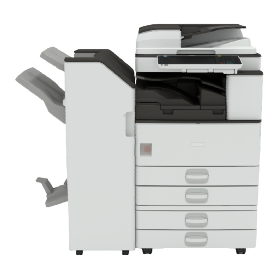
- Page 2 OR-C2 Training Appearance ARDF: Standard for some models Optional finisher Optional one- bin Tray Optional two-tray feed unit Slide 2 No additional notes...
- Page 3 OR-C2 Training D182/D183/D184 Service Training Product Overview Slide 3 This section provides an overview of the machine, and the options that can be installed.
- Page 4 OR-C2 Training What Models are there in the Series? Comparing Basic Specifications OR-C2a (D182) 25 cpm OR-C2b (D183) 30 cpm OR-C2c (D184) 33 cpm Controller: GW+ Contains new features introduced with the latest models that use this controller ...
- Page 5 OR-C2 Training What Models are there in the Series? Regional Variations in Standard Models SP model only 2 models 1 model 1 model 1) SP model, ARDF, normal SP model , no SP model , no ARDF is standard; operation panel ARDF, normal ARDF, normal Smart Operation...
- Page 6 OR-C2 Training Comparing Specifications with OR-C1 OR-C1 OR-C2 Operation panel 8.5 inches 9 inches RAM (maximum) 1 GB 1.5 GB 120 GB 250 GB Paper Feed Capacity (standard) 1150 1150 Paper Feed Capacity (max) 3150 3150 Warm-up Time w/ HDD: 20 s, w/o HDD: 14 s w/ HDD: 15.5 s, w/o HDD 14.5 s First Copy Time Scanning Speed (max)
- Page 7 OR-C2 Training Changes to the Engine The machine is the same as the OR-C1, except for the following points: Scanner: This is the same as the MET-C1. SBU board: This is also the same as the MET-C1. ...
- Page 8 OR-C2 Training Yield of Consumables Toner cartridges 360 g 11 k prints Same toner as OR-C1 Slide 8 Yields are based on these conditions: A4 (LT) long-edge feed 5% image coverage ratio...
- Page 9 OR-C2 Training Targets Average Print Volume OR-C2a: 4 k/month OR-C2b: 5 k/month OR-C2c: 7 k/month Slide 9 No additional notes...
-
Page 10: Reliability Information
OR-C2 Training Reliability Information PM Interval Components of the PCU: 60k Others: 120 k MPBF Target (Mainframe) OR-C2a: 102.6 k OR-C2b: 106.4 k OR-C2c: 111.1 k Call Ratio Target (Mainframe) OR-C2a: 0.039 ... - Page 11 OR-C2 Training Optional Hardware Peripherals 1bin-Tray ARDF Smart Operation Panel Platen Shift Tray 9inch WVGA 1000 sheet finisher Inner Finisher Bridge Unit 1000 sheet booklet finisher 1000×2LCT 550×1Bank 550×2Bank Caster Table Slide 11 If you install either of the 1000-sheet finishers, you must also install either the LCT or the two-tray paper tray unit.
- Page 12 OR-C2 Training Options: Original Feed Also used with these Similar to: Note models: D779: ARDF DF3090 MET-C1 K-C4 D700: Platen Cover PN2000 K-C4, MET-C1 D593: ADF Handle Type C OR-C1 Slide 12 No additional notes...
- Page 13 OR-C2 Training Options: Paper Feed Also used with these Similar to: Note models: D746: Paper Feed Unit OR-C1 2 trays PB3180 D579: Paper Feed Unit OR-C1 1 tray; only one of PB3120 these can be installed D747: LCIT PB3190 OR-C1 D593: Caster Table Type D OR-C1 Requires PB3120...
- Page 14 OR-C2 Training Options: Finishing Also used with these Similar to: Note models: D687: Finisher SR3140 MET-C1 1000-sheet D686: Booklet Finisher MET-C1 1000-sheet SR3150 D687: Finisher Adapter Type Needed for D686/D687 finishers D717: Punch Unit PU3050 MET-C1 For D686/D687 D586: Internal Finisher OR-C1 500-sheet SR3352...
- Page 15 OR-C2 Training Options: Controller Also used with Similar to: Note these models: D757: Postscript3 Unit Similar to Type M7 those used with other D758: Browser Unit Type models D758: SD card for NetWare printing Type M7 D757: IPDS Unit Type M7 D758: Hard Disk Drive For upgrading the Basic models Option Type M7...
- Page 16 OR-C2 Training Options: Controller Also used with these Similar to: Note models: D164: IEEE 802.11a/g/n MET-C1 Similar to those Interface Unit Type M2 used with other models D166: OCR Unit Type M2 CH-C1, MET-C1 D773: Smart Card Reader MET-C1 Built-in Unit Type M7 B679: IEEE 1284 Interface Used with many other Board Type A...
- Page 17 OR-C2 Training Options: Fax Also used with these Similar to: Note models: D759: Fax Option Type Similar to those used with other models D759: G3 Interface Unit Type M7 D757: Fax Connection Type M7 G578: Memory Unit Type In use with many B 32MB models D593: Handset Type 3352...
- Page 18 OR-C2 Training Options: Other Also used with these Similar to: Note models: B870: Optional Counter OR-C1 Similar to those Interface Unit Type A used with other models A674: Key Counter OR-C1 Bracket Type H D593: Card Reader OR-C1 Bracket Type 3352 D148: Smart Operation MET-C1 A new type of operation...
- Page 19 OR-C2 Training Smart Operation Panel Appearance 10.1inch WSVGA 1024x600 Main Power/Energy Home Key Saving LED Back key No ten-key pad Menu key Stop key No Start Button Check Status Key Fax LED Status LED Subject to change Data In LED Slide 19 No additional notes...
-
Page 20: Service Training
OR-C2 Training D182/D183/D184 Service Training New and Improved Features Slide 20 No additional notes... - Page 21 OR-C2 Training Java VM Feature Java VM was provided as an option on an SD card until now, but in this model, Java VM is mounted on the controller board (NAND flash memory) as standard. Slide 21 This change is to expand sales of SDK solution applications. ...
- Page 22 OR-C2 Training Updating the Java VM feature 12S and earlier models 12A and later models (From CH-C1) Website Website Firmware Download Center Firmware Download Center 1.Download the Java VM up-date tool 1.Download the Java VM firmware Option SD card Normal SD card (Not Optional SD card) Java 2.Save the new firmware on an SD card 2.Update Java VM feature on optional SD card on PC...
- Page 23 OR-C2 Training Re-install this feature if you replace the controller board When replacing a controller board, you need to confirm which SDK applications are installed, and re-install them. To check, look at the most recent list of optional features installed in this machine.
- Page 24 OR-C2 Training Embedded OCR (Searchable PDF) Overview Copy & Paste Search Scanning This function lets users add transparent text information on scanned documents. Searchable PDF is composed of two layers; Image-Layer and Text Layer. User can search specific words by using electronic search functions. ...
- Page 25 OR-C2 Training Embedded OCR (Searchable PDF) Notes about this Feature OCR can recognize texts even when there are multiple languages (easy words) in the scanned documents. When users choose Searchable PDF, invisible texts will be embedded in scanned images after scanning all input documents.
- Page 26 OR-C2 Training Embedded OCR (Searchable PDF) How it Works User Operations • Users’ basic operation does not differ from other scanner settings. • This function supports the following file types: PDF, High Compression PDF, and PDF/A. Send Searchable PDF to email •...
- Page 27 OR-C2 Training Embedded OCR (Searchable PDF) Remarks - 1 This function is provided as an option. Some models require a HDD option. Searchable PDF files cannot be stored in the Document Server. Preview cannot be used for Searchable PDF files. ...
- Page 28 OR-C2 Training Embedded OCR (Searchable PDF) Remarks - 2 When the scan resolution is set below 200dpi, OCR quality may not be good enough to create a Searchable PDF. As a result, Searchable PDF cannot be used. Therefore, Searchable PDF cannot be used when the resolution is set less than 200dpi.
-
Page 29: Capturing The Debug Logs
OR-C2 Training Capturing the Debug Logs - 1 Debug logs for the controller, engine, and operation panel (or optional Smart Operation Panel) can be transferred to an SD card in the SD slot on the operation panel. The controller debug is updated continuously during operation, but the engine debug log is only changed if an SC or jam occurs. - Page 30 OR-C2 Training Capturing the Debug Logs - 2 Insert the SD card into the slot on the side of the operation panel. Set the start date of the log with SP5-857-101 e.g.: March 28, 2013: input 20130328 (yyyymmdd) ...
- Page 31 OR-C2 Training Capturing the Debug Logs - 3 The debug logs are saved with the following file names and paths. Controller debug log (GW debug log): /LogTrace/machine number/watching/ yyyymmdd_hhmmss_unique identification number.gz Engine debug log: /LogTrace/machine number/engine/ yyyymmdd_hhmmss.gz ...
- Page 32 OR-C2 Training Import/Export of Settings Data This feature uses the SD card slot on the side of the operation panel. There is a procedure for user tool settings data, and another procedure for SP settings data. Import/export is possible between devices only if their model type, region of use, and the following device configurations match.
- Page 33 OR-C2 Training Import/Export of User Tool Settings Data - 1 To export data: Insert an SD card into the slot on the side of the operation panel. Log in at the operation panel as an administrator with all privileges.
- Page 34 OR-C2 Training Import/Export of User Tool Settings Data - 2 Data that can be imported and exported: Copier / Document Server Features Printer Features Scanner Features Facsimile Features Browser Features Extended Feature Settings ...
- Page 35 OR-C2 Training Import/Export of User Tool Settings Data - 3 Data that cannot be imported and exported: Extended Feature Settings Address book Programs (fax function) Programs (printer function) User stamp in Copier / Document Server Features ...
- Page 36 OR-C2 Training Import/Export of SP Settings Data - 1 System SP data, scanner SP data, fax SP data and printer SP data can be exported. To export data, insert an SD card and use SP5- 749-001 (Import/Export: Export). ...
- Page 37 OR-C2 Training Import/Export of SP Settings Data - 2 ‘Unique’ data: Unique information that can be updated » #1. Items that are to be used to identify the machine. – Example: Network Information/ Host name / Information related to fax number /Mail address assigned to the machine »...
- Page 38 OR-C2 Training Import/Export of SP Settings Data - 3 ‘Secret’ data: #1. Data that cannot be exported without being encrypted first. » Exported data is encrypted. » Example: Password / Encryption key / PIN code #2. Confidential information for the customer »...
-
Page 39: Service Training
OR-C2 Training D182/D183/D184 Service Training Installation Slide 39 This section explains the main points about installation. For full details, see the Field Service Manual. - Page 40 OR-C2 Training SMC Sheet Storage Location OR-C1 OR-C2 OR-C1: You have to remove the SMC sheet from the exposure glass and store it inside the ARDF or platen cover. OR-C2: The SMC sheet is stored inside the front cover (near the power switch) at the factory.
- Page 41 OR-C2 Training Options ARDF DF3090 When feeding thin paper, adjust the sliding tray to the point shown above [A]. When feeding normal paper, adjust the sliding tray to the point shown above [B]. If not, you may get the following problems: ...
- Page 42 OR-C2 Training Options Finishers The D686/D687 finishers are the same as for MET-C1. However, when installing on the OR-C2, Finisher Adapter Type M7 must be attached first. Slide 42 No additional notes...
- Page 43 OR-C2 Training Options Paper Tray Unit (two trays), LCT The casters are different from the OR-C1. The casters are adjustable. See the installation procedure in the service manual for details. Slide 43 No additional notes...
- Page 44 OR-C2 Training Options Smart Operation Panel The external keyboard bracket (used in MET-C1) is not required. After installation, do the following SP adjustments. Set SP5-748-201 bit 0 to 1 (default: 0). Set SP5-748-101 to 1 (default: 0). ...
- Page 45 OR-C2 Training Options SD Card Options In former models (such as Ap/At-C3), there are some SD card options that can’t be merged. In OR-C2, there are no restrictions. For example, the part of the Postscript software that requires licensing is now built into the controller, so the portion on the SD card can be moved to another SD card.
- Page 46 OR-C2 Training Options SD Card Storage Location Open the front cover, and then remove the bracket [A]. Keep the SD cards here [A]. Slide 46 No additional notes...
- Page 47 OR-C2 Training Embedded OCR (Searchable PDF) Installation - 1 Insert the OCR SD card in slot 1 or 2 Turn the main switch on. Execute SP 5-878-004 (Option setup: OCR dictionary) Turn the switch off and on. ...
- Page 48 OR-C2 Training Embedded OCR (Searchable PDF) Installation - 2 The machine’s serial number is saved on the OCR SD card during the first execution of SP5-878-004. At the same time, the OCR option’s serial number is saved in the machine’s NVRAM (on the controller board).
- Page 49 OR-C2 Training Embedded OCR (Searchable PDF) Troubleshooting 1. HDD broken Replace the HDD and copy the dictionary text information to the new HDD by using the original SD card again. 2. NVRAM broken/replaced If upload/download of NVRAM is not possible, order the OCR SD card as a service part and do the installation procedure again.
- Page 50 OR-C2 Training D182/D183/D184 Service Training Maintenance Slide 50 Replacement procedures are similar to the OR-C1 (except for taking the covers off, and for replacing PCBs). However, refer to the service manual for OR-C2 for details when doing replacements and adjustments.
-
Page 51: Important Notes
OR-C2 Training Important Notes With previous models, when the DC power was turned off, the supply of power from the AC control board to machine internal systems was stopped. With this model, even after the main switch/DC power has been turned off, a voltage of 5V still flows through the machine to detect when the switch is pushed to turn the power on. - Page 52 OR-C2 Training Caution Before Removing Components Even if you turn the power switch off, +5V is still supplied. So do the following before you start work. 1. Push the power switch [A] on the machine. 2. Wait 3 minutes to shut down. 3.
- Page 53 OR-C2 Training Covers To improve the appearance of the machine, screw holes are mostly not visible. This means that the covers are held in place by a lot of tabs. The locations of these tabs are explained in the removal procedures.
- Page 54 OR-C2 Training Starting the Machine Again To start the machine, press the main power switch. If you press the main power switch between the beginning and the end of a shutdown, the machine will not start. Slide 54 No additional notes...
-
Page 55: Forced Shutdown
OR-C2 Training Forced Shutdown In case normal shutdown does not complete for some reason, the machine has a forced shutdown function. To make a forced shutdown, press and hold the main power switch for 6 seconds. In general, do not use the forced shutdown. Forced shutdown may damage the hard disk and memory, and can cause damage to the machine. - Page 56 OR-C2 Training Replacing the NVRAM on the Controller Board See the following section of the manual for full details: Replacement and Adjustment > PCBs and Other Items > NVRAM on the Controller Board When replacing the controller board, remove the NVRAM from the old controller board.
-
Page 57: Replacing The Controller Board
OR-C2 Training Replacing the Controller Board - 1 Before replacing the controller board, check which ESA applications have been installed. After replacing the controller board, re-install the ESA applications by following the installation instructions for each application. After reinstalling the ESA applications, print the SMC with SP-5-990-024/025. - Page 58 OR-C2 Training Replacing the Controller Board - 2 When removing the controller board, remove the board horizontally to the left so as not to damage the SD card slot [A] on the rear of the board. Slide 58 No additional notes...
- Page 59 OR-C2 Training Replacing the EEPROM on the BCU Board See the following section of the manual for full details: Replacement and Adjustment > PCBs and Other Items > EEPROM on the BCU Install the EEPROM [A] the correct way around. ...
- Page 60 OR-C2 Training D182/D183/D184 Service Training Detailed Section Descriptions Scanner Slide 60 This section describes the scanner. It is the same as MET-C1.
-
Page 61: Scanner Unit
OR-C2 Training Scanner Unit The machine uses a CCD for scanning. 1. Scanner HP sensor 2. DF exposure glass 3. 2nd scanner (2nd carriage) 4. Scanner lamp 5. 1st scanner (1st carriage) 6. Exposure glass 7. Scanner motor 8. Sensor board unit (SBU) 9. -
Page 62: Scanner Drive
OR-C2 Training Scanner Drive The scanner motor [A] drives the 1st scanner [B] and the 2nd scanner [C] through the scanner drive pulley, scanner drive shaft [D], and two scanner wires [E]. In ARDF mode, the scanners always stay in their home position (the scanner HP sensor [F] detects the 1st scanner). - Page 63 OR-C2 Training Original Size Detection – Platen Mode There are no original width sensors in the scanner unit. The CCD detects the original width. The APS length sensors [A] detect the original length. The BCU board checks the sensors when the platen cover sensor [B] is activated as it is closed.
- Page 64 OR-C2 Training Original Size Detection – Notes By changing SP4-305-001, you can change between A4 size/letter size and Chinese paper size (8×16). If the user specifies that the pre-scan lamp is too bright, the brightness for the pre-scan can be reduced by decreasing the value of SP4-309-004.
- Page 65 OR-C2 Training ADF Exposure Glass: No contact vs Contact Mylar No contact Contact Originals that have sticky substances on the surface may cause streaks on the exposure glass. To prevent these streaks, the ADF exposure glass has a mylar, which guides the original over the glass so that it does not contact the glass.
- Page 66 OR-C2 Training Dust Detection – Overview This function checks the ADF exposure glass for dust that can cause black lines in copies. The dust check is done before the first original is scanned. This is done only once at the beginning of a job. The check is not done for originals added during a long scanning job.
- Page 67 OR-C2 Training Dust Detection - SP 4020 SP 4020 001: Enable/disable (default – disabled) SP 4020 002: Sensitivity adjustment SP 4020 003: Do not adjust in the field SP 7852: Counts how many times the machine detected dust on the ADF.
- Page 68 OR-C2 Training Dust Detection – Action Taken When dust detection determines that dust exists, the scan point shifts in order to avoid the dust. There are three scanning points. a: Home position b: The first time that dust is detected, the scanner moves here. ...
- Page 69 OR-C2 Training OPTIONAL PERIPHERALS Optional Finishers (D686/D687) Slide 69 No additional notes...
- Page 70 OR-C2 Training Overview Slide 70 No additional notes...
- Page 71 OR-C2 Training What are the D686 and D687 Finishers? 1000-sheet Booklet Finisher D686 This finisher has three trays: a proof tray on top of the finisher, an upper (shift) tray, and a lower tray for booklets. This is a replacement for the B793 finisher. »...
-
Page 72: General Layout
OR-C2 Training General Layout Proof Tray Three trays. Punch Unit Proof tray Shift tray Booklet tray Stapler The shift tray can be used Unit Shift Tray for shift-sorting and stapling. The proof tray cannot be used for these two functions. - Page 73 OR-C2 Training Compare with the B793 Finisher - 1 D686 B793 Shift Tray Stapler Unit Stapler Unit Booklet Folder Booklet Folder Slide 73 No additional notes...
- Page 74 OR-C2 Training Compare with the B793 Finisher - 2 Better for thick paper D686/D687 has a less severe bend going back to the stapler tray from the shift tray. So, heavier paper can be stapled than in the B793. ...
-
Page 75: Proof Tray
OR-C2 Training Proof Tray Proof Tray Full Sensor No shift-sorting or Proof Tray up/down mechanism. Exit Sensor Proof tray junction gate solenoid: Drops the junction gate Proof tray full sensor: Detects when the tray is full Proof tray exit sensor: Detects jams Proof Tray Junction Gate... -
Page 76: Shift Tray
OR-C2 Training Shift Tray Has shift-sorting and up/down mechanism. Proof tray junction gate solenoid: Does not turn This is the default mode. Proof Tray Junction Gate Slide 76 No additional notes... -
Page 77: Shift Tray - Up/Down Mechanism
OR-C2 Training Shift Tray – Up/Down Mechanism Upper Limit Shift tray motor: Moves Switch Shift Tray the tray up/down until the Position Sensor top of the stack is at the correct position Shift tray position sensor: Detects the top of the stack when it is at the correct position ... -
Page 78: Shift Tray - Side-To-Side Mechanism
OR-C2 Training Shift Tray – Side-to-side Mechanism Paper Eject Shift Sensor Motor Shift HP Sensor Shift Roller Shift motor: Moves the shift roller from side to side, after the paper eject sensor detects the trailing edge of the paper ... - Page 79 OR-C2 Training Booklet Tray - Overview Tray Full Sensors Sensor Depressor This tray does not have a lift mechanism. Two sensors detect when the tray is full. The actuators for these sensors are attached to the sensor arm. ...
- Page 80 OR-C2 Training Booklet Tray – Stacking Sensor Depressor The sensor arm rests on the top of the booklets. The depressor pushes the open ends of the booklets down. This lets the machine stack more booklets on the tray. Slide 80 No additional notes...
- Page 81 OR-C2 Training Booklet Tray – Tray Full Sensors Rear Tray Full Front Tray Full Sensor Sensor Full 3 Ready Full 1 Full 2 No tray The sensors detect four conditions. Ready, Full 1, Full 2, Full 3 The three ‘Full’ conditions are not ‘half-full’, ‘almost full’, and ‘completely full’.
- Page 82 OR-C2 Training Stoppers for Stapling Upper Stopper - 1 Used for the following: Corner stapling: All paper sizes Booklet stapling: B5, A4, LT Slide 82 This is similar to the B793 finisher.
- Page 83 OR-C2 Training Stoppers for Stapling Upper Stopper - 2 Upper Retraction Motor At the start of the set, the upper retraction motor starts. This motor does two things. The stopper moves down to catch the paper. The upper clamp roller contacts the stack.
- Page 84 OR-C2 Training Stoppers for Stapling Upper Stopper - 3 At the end of the Upper Clamp set, the stopper Roller Motor moves away. The upper clamp roller feeds the stack to the correct position for stapling. Driven by the upper clamp roller motor Upper Stopper...
- Page 85 OR-C2 Training Stoppers for Stapling Lower Stopper - 1 Used for the following: Booklet stapling: LG, B4, A3, DLT, 12"x17.7" Slide 85 This is similar to the B793 finisher.
- Page 86 OR-C2 Training Stoppers for Stapling Lower Stopper - 2 Lower Stopper Bracket Pawl At the start of the set, the stapler moves to the center. A bracket on the stapler pushes the stopper, and the pawl moves into the correct position to catch the leading edge of the paper. ...
- Page 87 OR-C2 Training Stacking in the Stapler Tray Reverse Roller Lower Transport Motor Positioning Rollers To send the paper to the stapler, the paper must be fed back into the machine. The lower transport motor drives the reverse roller, which feeds the paper into the stapler.
-
Page 88: Jogger Unit
OR-C2 Training Jogger Unit Jogger HP Sensor Jogger Motor Jogger Fences Jogger motor: Moves the jogger fences every job Slide 88 This is basically the same as the B793 finisher. -
Page 89: Stapler Unit Movement
OR-C2 Training Stapler Unit Movement Sensor Motor Stapler unit motor: Moves the stapler from side to side Stapler HP sensor: After the job, the stapler moves back to this position Slide 89 This is basically the same as the B793 finisher. - Page 90 OR-C2 Training Corner Stapling One Staple The home position is at the front of the machine. The stapler moves to the stapling position, which is at the rear of the machine, and inserts the staple. The stapler stays at the rear until all copies are stapled, then comes back to home position.
- Page 91 OR-C2 Training Corner Stapling Two Staples On the first copy, the stapler inserts the first staple at the rear of the machine, and the second at the front of the machine. Then the first copy is fed out. For the second copy, the first staple is inserted at the front. Then the stapler moves to the rear and inserts the second staple.
- Page 92 OR-C2 Training Booklet Stapling B5, A4, LT The stapler moves from the home position to the rear of the machine, then to the center. The stapler then moves to the first stapling position, towards the rear from the center, and inserts the staple. ...
- Page 93 OR-C2 Training Booklet Stapling LG, B4, A3, DLT, 12"x17.7" The stapler first moves to the center position. At this position, the bracket on the stapler releases the lower stopper, which is necessary to catch the bottom edge of long paper. ...
- Page 94 OR-C2 Training Exit Guide Plate Open/Close Motor For no stapling, no shift tray side-to-side motion: Sensor The exit guide plate stays down Shift tray side-to-side motion When the shift motor starts, the exit guide plate motor lifts the exit guide plate.
- Page 95 OR-C2 Training Stack Feed-out Stack feed-out motor: Feeds the stapled stack out of the jogger tray Stack feed out belt HP sensor: Detects when the belt is at home position The pawl is next to the HP sensor at HP. This keeps it away from the stapler when it moves.
- Page 96 OR-C2 Training Booklet Feed Through the Stapler - 1 These rollers feed Upper Clamp the stack into the Roller Motor stapler and out to the booklet folder, and apply pressure to the stack during this process. Lower Clamp Roller Motor Upper Clamp Rollers...
- Page 97 OR-C2 Training Booklet Feed Through the Stapler - 2 This shows a side view of Upper Clamp the mechanism that we Rollers have just described. Lower Clamp Rollers Slide 97 No additional notes...
- Page 98 OR-C2 Training Booklet Feed Into the Folder - 1 The lower clamp rollers feed the stack of paper down towards the folder. The bottom fence is lifts the stack to the folding position, based Lower Clamp on the paper size used Rollers for the booklet.
- Page 99 OR-C2 Training Booklet Feed Into the Folder - 2 Fold Roller Motor Clamp Rollers Lower Retraction Motor Bottom Fence Lift Motor Bottom Fence Slide 99 This diagram is from the B793. The mechanism is similar.
- Page 100 OR-C2 Training Fold Plate Drive Mechanism Fold Plate Cam HP HP Sensor Sensor Fold Plate Fold Plate Motor A motor and cam drive the fold plate. The fold plate and cam both have home position sensors, to control the folding operation. Slide 100 ...
- Page 101 OR-C2 Training Fold Roller Drive Mechanism Fold Roller The fold roller motor Motor Fold Rollers drives these rollers. Springs apply pressure between the rollers. Slide 101 This is similar to the B793 finisher.
- Page 102 OR-C2 Training Punch Unit - Overview This punch unit has two new mechanisms to make the positions of punch holes more accurate Skew correction » The punch unit corrects skew in the paper before the holes are punched. ...
- Page 103 OR-C2 Training Punch Unit Operation Skew Correction Finisher Entrance Roller Finisher Entrance Sensor Finisher entrance sensor: Detects the leading edge of the sheet Finisher entrance roller: Stops for a short time, to correct skew These SPs control the skew correction mechanism ...
- Page 104 OR-C2 Training Punch Unit Operation Punch Hole Position Correction - 1 The paper position sensor Paper Position is moved until it detects Sensor the edge of the paper. This measures the distance of the paper from the ideal central position in the feed path.
- Page 105 OR-C2 Training Punch Unit Operation Punch Hole Position Correction - 2 Punch Unit Paper Position Sensor The paper position sensor moves back to home position. The rollers feed the paper to the punch position. The punch unit moves across the page, to put the holes in the correct position.
- Page 106 OR-C2 Training Punch Unit Operation Punch Hole Position Correction - 3 The paper is fed out of the punch unit. Punch hole position adjustments SP 6128: Moves the position parallel to the feed direction SP 6129: Moves the punch position perpendicular to the feed direction...
-
Page 107: Paper Position Detection
OR-C2 Training Paper Position Detection Paper Position Sensor Paper Position HP Sensor Paper Position Sensor Slide Motor The motor moves the sensor across the paper feed path until the sensor detect the edge of the paper. Slide 107 The other sensor in the diagram is a home position sensor. -
Page 108: Punch Unit Movement
OR-C2 Training Punch Unit Movement Punch Unit Punch Movement Motor Punch movement motor: Moves the punch unit across until it is in the correct position. Punch drive motor (see the next slide): Puts the punch holes in the paper. Slide 108 No additional notes... - Page 109 OR-C2 Training Punching - 1 Punch Drive Motor Encoder Wheel Punch Punch Waste Hopper Full Sensor First, the punch drive motor turns the encoder wheel until it is at the correct home position. The home position for 2-hole punching is different from the home position for 3-hole punching.
- Page 110 OR-C2 Training Punching - 2 Punch Drive Motor Punch Gear Sensor Two-hole punching (top diagram): The motor drives clockwise then reverse. Three-hole punching (bottom diagram): First the punch gear is turned 180 degrees, then the motor drives clockwise then reverse Slide 110 No additional notes...
- Page 111 OR-C2 Training Adjustments SP modes 6134: Stapling position 6136: Booklet stapling position 6132: Position of jogger fences 6137: Folder position adjustment Dip switches SW100: Stapling position SW101: Jogger fence position If you adjust a dip switch setting, open and close the finisher cover to enable the new setting.
-
Page 112: Replacement And Adjustment
OR-C2 Training Replacement and Adjustment Stapler Unit After you remove this, a special tool is needed when you reassemble the machine. The stapler unit has two parts. The special tool holds the two parts in the correct positions. ... - Page 113 OR-C2 Training Smart Operation Panel Smart Operation Panel Type M3 (D148) Slide 113 No additional notes...
- Page 114 OR-C2 Training Appearance - 1 Home key Main power / Energy save LED Back key (Only used for Android Apps) Menu key (Only used for Android Apps) Stop key Check status key Fax LED Status LED “Data In” LED There are few hard keys. ...
- Page 115 OR-C2 Training Appearance - 2 The operation panel has SD / USB slots. There is a Reset key for Android. Slide 115 No additional notes...
-
Page 116: Basic Information
OR-C2 Training Basic information - 1 There are two kinds of applications. 1) Android applications You can use “flick input” and “swiping”. You can use “Menu” and “Back” keys. These keys only light for Android applications. - Page 117 OR-C2 Training Basic information - 2 You can customize the Home display. You can add widgets (Toner remaining, clock, language and so on) and applications. Please push and hold on the Home display Select the object which you want to add. ...
- Page 118 OR-C2 Training Basic information - 3 SC or machine status is displayed in legacy mode. There is no independent Address Book or Authentication for Android. Slide 118 No additional notes...
-
Page 119: System Configuration
OR-C2 Training System Configuration [A] Android Operation Panel [B] Android (OS) firmware Version update via recovery mode [C] Android apps Version update via op panel service mode. Slide 119 No additional notes... - Page 120 OR-C2 Training Start up There are two start up displays: GW controller and Android) GW controller Android Slide 120 No additional notes...
-
Page 121: Screen Start Up Mode
OR-C2 Training Screen start up mode There are two modes for screen start up Normal (Default) Low electricity mode. It takes some time to start up the operation panel (about 68 seconds). Quick Supplying electricity for the operation panel is continued while the machine power is off, to start up quickly (about 18 seconds). - Page 122 OR-C2 Training Special shut down mode There are two special shut down modes. Shut down for maintenance. » When “Quick” start up mode is set, just enough power is supplied to keep the panel in sleep condition. • Procedure: Turn the power off while pushing the “Stop” key.
-
Page 123: Service Modes
OR-C2 Training Service Modes There are three SP modes. Contact your supervisor for details on how to access these. Machine service mode Android operation panel service mode Recovery mode: Needed for updating firmware, and for android system recovery Slide 123 ... - Page 124 OR-C2 Training Slide 124 The End...