SolarEdge SE K Series Quick Installation Manual
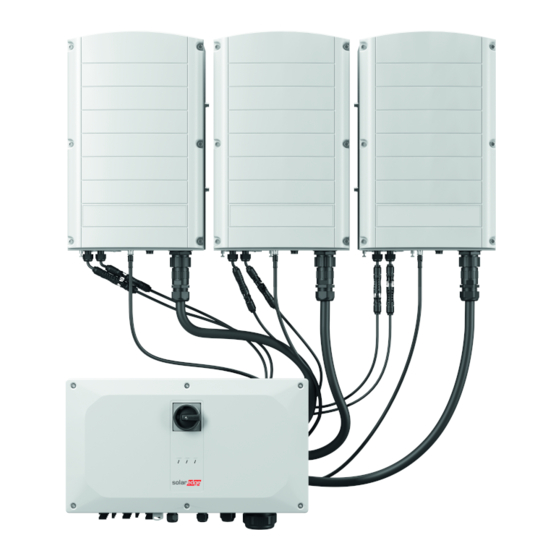
Three phase inverter with synergy technology
Hide thumbs
Also See for SE K Series:
- Quick installation manual (288 pages) ,
- Installation manual (105 pages) ,
- Quick installation manual (47 pages)

Related Manuals for SolarEdge SE K Series


Summary of Contents for SolarEdge SE K Series
- Page 1 Three Phase Inverter with Synergy Technology Quick Installation Guide PN: SExxK-xxxxIxxxx Scan for full installation guide For North America Version 1.3...
- Page 2 SAVE THESE INSTRUCTIONS – This manual contains important instructions for the Three Phase Inverter with Synergy Technology that should be followed during installation and maintenance. Using this equipment in a manner not specified in this guide by SolarEdge may impair the protection provided by this equipment.
-
Page 3: Installing The Power Optimizers
Installing the Power Optimizers 3 4 5 6 Use SolarEdge Designer Download SolarEdge Mapper to map string Power Optimizers to design SE system https://designer.solaredge.com Download MAN-01-00786-1.3... - Page 4 Installing the Power Optimizers 5 6 Scan QR code using Mapper Install Power Optimizer 10 mm / 0.4" M6 (1/4’’) or M8 (5/16”) 25 mm / 1" stainless steel 9.5 N*m / 7 lb*ft (P860, P960) 12.7 mm / 0.5”...
- Page 5 Installing the Power Optimizers Connect input from Module 2:1 series connection Connect output to String Use a dual input optimizer (P800p) for parallel connection of two PVs or use a branch cable to connect two PVs to a single input optimizer. MAN-01-00786-1.3...
-
Page 6: Connecting The Pv Array
Connecting the PV Array Check array polarity. V erify 1±0.1V per optimizer Example: 8 optimizers = ~8V MAN-01-00786-1.3... - Page 7 Maintaining Clearance 15 cm / 6” Indoor Clearance 20 cm / 8” where annual average high temperature equals or above 25˚C / 77˚F 40 cm / 16” Outdoor Clearance 10 cm / 4” 5 cm / 2” Horizontal Installation WARNING! Area in front of the inverter must be kept clear for at...
- Page 8 Marking & Drilling Holes Level provided template horizontally 6.1” / 15.5 cm 6.1” / 15.5 cm Drill holes 3.3” / 9.3 cm 3.3” / 9.3 cm Mark holes Optional Optional Ø 9mm / 0.35” Avoid wobbly installation by adding back support Position provided template vertically Optional unit - model dependent 7.36”...
-
Page 9: Mounting The Units
Mounting the Units 2.9 lb.*ft. For left or right units, use only the outer screw 2.9 lb.*ft. 2.9 lb.*ft. 2.9 lb.*ft. 18KG 32KG MAN-01-00786-1.3... -
Page 10: Connecting Cables
Connecting Cables Align pin grooves in connector with pin guides in socket Connect cables CAUTION! Do not according to labels block Airflow Boundary for single conduit entry. Max conduit size 3” Max conduit Max conduit size 2.5” CAUTION! Remove plates size 2”... -
Page 11: Removing Covers
Removing Covers WARNING DISCONNECT POWER BEFORE BEGINNING INSTALLATION MAN-01-00786-1.3... - Page 12 Connecting PV Strings (Option 1) When using a stranded wire, use of ferrule is at the installer discretion 6 - 12 AWG ” 18 mm Ground conduit nut if required by regulation Up to 12 Strings MAN-01-00786-1.3...
- Page 13 Important: When installing a system with more than 3 strings per a single Synergy Unit (whether connected directly or via a combiner box), fuses are required. In SolarEdge system, Ferrule 25A fuses shall be used Max 2 AWG...
- Page 14 Connecting AC and Protective Earth The inverter can either support 4 wire + PE or 3 wire + PE connection Overcurrent protection for the AC output must be provided by others, see manual for guidance Max 1.39” / 33 mm Ø...
-
Page 15: Lan Communication
LAN Communication COMM 1 4 lb*ft Ethernet MAN-01-00786-1.3... - Page 16 RS485 Connection of Multiple Inverters Move SW1 switch to ON (up) to terminate first and last inverters on RS485 bus COMM 2 3 lb*ft RS485-1 CAT6, 3-wire, shielded, twisted pair (0.2- 1 mm²) max 1km / 3300 ft. MAN-01-00786-1.3...
- Page 17 Connecting Wi-Fi Communication (Optional) 4 lb*ft MAN-01-00786-1.3...
- Page 18 Connecting Cellular Communication (Optional) 3 lb*ft MAN-01-00786-1.3...
-
Page 19: Installing Covers
Installing Covers 2.6 lb*ft MAN-01-00786-1.3... - Page 20 Pre-commissioning when AC Power is Not Connected (Option 1) Download SolarEdge SetApp Turn switch to ON Connect power bank Start and follow SetApp Start Download Power bank: 60W output port , USB-C Power Delivery (PD): 20V 3A (not provided) Cover connector when not used 3.3 ft / 1 meter, USB-C / USB-C (not provided)
- Page 21 Commissioning with DC and AC Power (Option 2) Turn switches to ON Download Start & follow SetApp SolarEdge SetApp Start Download MAN-01-00786-1.3...
- Page 22 Commissioning the Leader Inverter Commissioning Country & Language Pairing Solaredge Leader Site Communication RS485-1 Protocol SolarEdge Follower Detect RS485-1 Inverter Units Status MAN-01-00786-1.3...
-
Page 23: Led Indications
LED Indications POWER COMM FAULT Green Blue System is producing Power AC is connected but the system is not producing power Inverter is communicating with the monitoring platform System error MAN-01-00786-1.3... - Page 24 Support Contact Information If you have technical problems concerning SolarEdge products, please contact us: https://www.solaredge.com/service/support Subject to change without notice. Copyright © SolarEdge Inc. All rights reserved. July 2021.