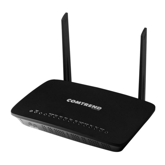
Comtrend Corporation NexusLink 3120 User Manual
Adsl/vdsl bonding router
Hide thumbs
Also See for NexusLink 3120:
- Connection manual (2 pages) ,
- Setup manual (12 pages) ,
- User manual (103 pages)

Related Manuals for Comtrend Corporation NexusLink 3120


Summary of Contents for Comtrend Corporation NexusLink 3120
- Page 1 NexusLink 3120 A/VDSL Bonding Router User Manual Version A1.2, May 17, 2017 261103-019...
- Page 2 Preface This manual provides information related to the installation and operation of this device. The individual reading this manual is presumed to have a basic understanding of telecommunications terminology and concepts. If you find the product to be inoperable or malfunctioning, please contact technical support for immediate service by email at INT-support@comtrend.com For product update, new product release, manual revision, or software upgrades,...
- Page 3 User Information Any changes or modifications not expressly approved by the party responsible for compliance could void your authority to operate the equipment. Aucune modification apportée à l’appareil par l’utilisateur, quelle qu’en soit la nature. Tout changement ou modification peuvent annuler le droit d’utilisation de l’appareil par l’utilisateur.
- Page 4 Radiation Exposure 1. This Transmitter must not be co‐located or operating in conjunction with any other antenna or transmitter. 2. This equipment complies with FCC RF radiation exposure limits set forth for an uncontrolled environment. This equipment should be installed and operated with a minimum distance of 20 centimeters between the radiator and your body.
- Page 5 Copyright Copyright©2017 Comtrend Corporation. All rights reserved. The information contained herein is proprietary to Comtrend Corporation. No part of this document may be translated, transcribed, reproduced, in any form, or by any means without prior written consent of Comtrend Corporation.
-
Page 6: Table Of Contents
Table of Contents CHAPTER 1 INTRODUCTION ......................8 CHAPTER 2 INSTALLATION ......................9 2.1 H ........................... 9 ARDWARE ETUP 2.2 LED I ........................... 11 NDICATORS CHAPTER 3 WEB USER INTERFACE .................... 13 3.1 D ........................13 EFAULT ETTINGS 3.2 IP C ........................ - Page 7 5.6.4 USB Speed ..........................72 CHAPTER 6 ADVANCED SETUP ..................... 73 6.1 A ....................... 73 DETECTION SETUP 6.2 S ............................78 ECURITY 6.2.1 IP Filtering ........................78 6.2.2 MAC Filtering......................... 82 6.3 Q S) ......................84 UALITY OF ERVICE 6.3.1 QoS Queue ........................
- Page 8 8.5 I ........................... 149 NTERNET 8.6 A ........................150 CCESS ONTROL 8.6.1 Accounts ........................... 150 8.6.2 Services ..........................152 8.6.3 IP Address ......................... 153 8.7 W -LAN ........................... 154 8.8 U ........................155 PDATE OFTWARE 8.9 R ............................156 EBOOT CHAPTER 9 LOGOUT ........................
-
Page 9: Chapter 1 Introduction
Chapter 1 Introduction NexusLink 3120 is a Multi-DSL bonding router using the BCM 63138. It not only provides both ADSL and VDSL but also supports xDSL bonding for extending WAN access bandwidth. Integrated 5 Giga Ethernet ports support WLAN 802.11n 2.4GHz and 802.11ac 5GHz Frequency bands. -
Page 10: Chapter 2 Installation
NOTE: If pressed down for more than 60 seconds, the NexusLink 3120 will go into a firmware update state (CFE boot mode). The firmware can then be updated using an Internet browser pointed to the default IP address. - Page 11 ETH WAN PORT This port has the same features as the LAN ports described below with additional Ethernet WAN functionality. Ethernet (LAN) Ports Use 1000-BASE-T RJ-45 cables to connect up to four network devices to a Gigabit LAN, or 10/100BASE-T RJ-45 cables for standard network usage. These ports are auto-sensing MDI/X;...
-
Page 12: Led Indicators
2.2 LED Indicators The front panel LED indicators are shown below and explained in the following table. This information can be used to check the status of the device and its connections. Color Mode Function The device is powered up. GREEN The device is powered down. - Page 13 The wireless module is ready. (i.e. installed and enabled). WiFi GREEN The wireless module is not ready. (i.e. either not installed or disabled). Blink Data transmitting or receiving over WLAN. xDSL Link is established. The device is powered down. DSL 1 GREEN Blink The xDSL link is training or some traffic is passing...
-
Page 14: Chapter 3 Web User Interface
Chapter 3 Web User Interface This section describes how to access the device via the web user interface (WUI) using an Internet browser such as Internet Explorer (version 5.0 and later). 3.1 Default Settings The factory default settings of this device are summarized below. ... -
Page 15: Ip Configuration
3.2 IP Configuration DHCP MODE When the NexusLink 3120 powers up, the onboard DHCP server will switch on. Basically, the DHCP server issues and reserves IP addresses for LAN devices, such as your PC. To obtain an IP address from the DCHP server, follow the steps provided below. - Page 16 STATIC IP MODE In static IP mode, you assign IP settings to your PC manually. Follow these steps to configure your PC IP address to use subnet 192.168.1.x. NOTE: The following procedure assumes you are running Windows XP. However, the general steps involved are similar for most operating systems (OS).
-
Page 17: Login Procedure
3.3 Login Procedure Perform the following steps to login to the web user interface. NOTE: The default settings can be found in section 3.1 Default Settings. STEP 1: Start the Internet browser and enter the default IP address for the device in the Web address field. - Page 18 STEP 3: After successfully logging in for the first time, you will reach this screen. You can also reach this page by clicking on the following icon located at the top of the screen.
-
Page 19: Chapter 4 Device Information
Chapter 4 Device Information You can reach this page by clicking on the following icon located at the top of the screen. The web user interface window is divided into two frames, the main menu (on the left) and the display screen (on the right). The main menu has several options and selecting each of these options opens a submenu with more selections. -
Page 20: Wan
4.1 WAN Select WAN from the Device Info submenu to display the configured PVC(s). Heading Description Interface Name of the interface for WAN Description Name of the WAN connection Type Shows the connection type VlanMuxId Shows 802.1Q VLAN ID IPv6 Shows WAN IPv6 status Igmp Pxy Shows Internet Group Management Protocol (IGMP) -
Page 21: Statistics
4.2 Statistics This selection provides LAN, WAN, ATM and xDSL statistics. NOTE: These screens are updated automatically every 15 seconds. Click Reset Statistics to perform a manual update. 4.2.1 LAN Statistics This screen shows data traffic statistics for each LAN interface. Heading Description Interface... -
Page 22: Wan Service
4.2.2 WAN Service This screen shows data traffic statistics for each WAN interface. Heading Description Interface WAN interfaces Description WAN service label Received/Transmitted - Bytes Number of Bytes - Pkts Number of Packets - Errs Number of packets with errors - Drops Number of dropped packets... -
Page 23: Xtm Statistics
4.2.3 XTM Statistics The following figure shows ATM (Asynchronous Transfer Mode)/PTM (Packet Transfer Mode) statistics. XTM Interface Statistics Heading Description Port Number ATM PORT (0-1) In Octets Number of octets received over the interface Out Octets Number of octets transmitted over the interface In Packets Number of packets received over the interface Out Packets... -
Page 24: Xdsl Statistics
4.2.4 xDSL Statistics The xDSL Statistics screen displays information corresponding to the xDSL type. The two examples below (VDSL & ADSL) show this variation. VDSL... - Page 25 ADSL Click the Reset Statistics button to refresh this screen. Field Description Mode VDSL, VDSL2 Traffic Type ATM, PTM Status Lists the status of the DSL link Link Power State Link output power state...
- Page 26 Field Description phyR Status Shows the status of PhyR™ (Physical Layer Re-Transmission) impulse noise protection Line Coding (Trellis) Trellis On/Off SNR Margin (0.1 dB) Signal to Noise Ratio (SNR) margin Attenuation (0.1 dB) Estimate of average loop attenuation in the downstream direction Output Power Total upstream output power...
- Page 27 Data Cells Total number of ATM data cells Bit Errors Total number of bit errors Total ES Total Number of Errored Seconds Total SES Total Number of Severely Errored Seconds Total UAS Total Number of Unavailable Seconds xDSL BER TEST Click xDSL BER Test on the xDSL Statistics screen to test the Bit Error Rate (BER).
- Page 28 xDSL TONE GRAPH Click Draw Graph on the xDSL Statistics screen and a pop-up window will display the xDSL statistics graph, including SNR, Bits per tone, QLN and Hlog of the xDSL line connection, as shown below.
-
Page 29: Route
4.3 Route Choose Route to display the routes that the NexusLink 3120 has found. Field Description Destination Destination network or destination host Gateway Next hop IP address Subnet Mask Subnet Mask of Destination Flag U: route is up !: reject route... -
Page 30: Arp
4.4 ARP Click ARP to display the ARP information. Field Description IP address Shows IP address of host PC Flags Complete, Incomplete, Permanent, or Publish HW Address Shows the MAC address of host PC Device Shows the connection interface 4.5 DHCP Click DHCP to display all DHCP Leases. - Page 31 Field Description IPv6 Address Shows IP address of device/host/PC MAC Address Shows the Ethernet MAC address of the device/host/PC Duration Shows leased time in hours Expires In Shows how much time is left for each DHCP Lease...
-
Page 32: Nat Session
4.6 NAT Session This page displays all NAT connection session including both UPD/TCP protocols passing through the device. Click the “Show All” button to display the following. Field Description Source IP The source IP from which the NAT session is established Source Port The source port from which the NAT session is established Destination IP... -
Page 33: Igmp Info
4.7 IGMP Info Click IGMP Info to display the list of IGMP entries broadcasting through IGMP proxy enabled wan connection. Field Description Interface The Source interface from which the IGMP report was received The WAN interface from which the multicast traffic is received Groups The destination IGMP group address Member... -
Page 34: Ipv6
4.8 IPv6 4.8.1 IPv6 Info Click IPv6 Info to display the IPv6 WAN connection info. Field Description Interface WAN interface with IPv6 enabled Status Connection status of the WAN interface Address IPv6 Address of the WAN interface Prefix Prefix received/configured on the WAN interface Device Link-local Address The CPE's LAN Address Default IPv6 Gateway... -
Page 35: Ipv6 Neighbor
4.8.2 IPv6 Neighbor Click IPv6 Neighbor to display the list of IPv6 nodes discovered. Field Description IPv6 Address Ipv6 address of the device(s) found Flags Status of the neighbor device HW Address MAC address of the neighbor device Device Interface from which the device is located... -
Page 36: Ipv6 Route
4.8.3 IPv6 Route Click IPv6 Route to display the IPv6 route info. Field Description Destination Destination IP Address Gateway Gateway address used for destination IP Metric Metric specified for gateway Interface Interface used for destination IP... -
Page 37: Cpu & Memory
4.9 CPU & Memory Displays the system performance graphs. Shows the current loading of the CPU and memory usage with dynamic updates. -
Page 38: Network Map
4.10 Network Map The network map is a graphical representation of router’s wan status and LAN devices. Note: This graph is unavailable for Internet Explorer users. 4.11 Wireless 4.11.1 Station Info This page shows authenticated wireless stations and their status. Click the Refresh button to update the list of stations in the WLAN. - Page 39 Consult the table below for descriptions of each column heading. Field Description Lists the MAC address of all the stations. Associated Lists all the stations that are associated with the Access Point, along with the amount of time since packets were transferred to and from each station.
-
Page 40: Site Survey
4.11.2 Site Survey The graph displays wireless APs found in your neighborhood by channel. 2.4GHz... - Page 41 5GHz...
-
Page 42: Chapter 5 Basic Setup
Chapter 5 Basic Setup You can reach this page by clicking on the following icon located at the top of the screen. This will bring you to the following screen. -
Page 43: Wan Setup
5.1 Wan Setup Add or remove ATM, PTM and ETH WAN interface connections here. Click Add to create a new Layer 2 Interface (see Appendix F - Connection Setup). NOTE: Up to 16 ATM interfaces can be created and saved in flash memory. To remove a connection, click the Remove button. -
Page 44: Wan Service Setup
5.1.1 WAN Service Setup This screen allows for the configuration of WAN interfaces. Click the Add button to create a new connection. For connections on ATM or PTM or ETH WAN interfaces see Appendix F - Connection Setup. To remove a connection, select its Remove column radio button and click Remove. Heading Description Interface... -
Page 45: Nat
5.2 NAT For NAT features under this section to work, NAT must be enabled in at least one PVC. 5.2.1 Virtual Servers Virtual Servers allow you to direct incoming traffic from the WAN side (identified by Protocol and External port) to the internal server with private IP addresses on the LAN side. - Page 46 Consult the table below for field and header descriptions. Field/Header Description Choose All Interface Virtual server rules will be created for all WAN interfaces. Choose One Interface Select a WAN interface from the drop-down menu. Use Interface Select a Service User should select the service from the list.
-
Page 47: Port Triggering
5.2.2 Port Triggering Some applications require that specific ports in the firewall be opened for access by the remote parties. Port Triggers dynamically 'Open Ports' in the firewall when an application on the LAN initiates a TCP/UDP connection to a remote party using the 'Triggering Ports'. - Page 48 Field/Header Description Use Interface Select a WAN interface from the drop-down menu. Select an Application User should select the application from the list. Custom Application User can enter the name of their choice. Trigger Port Start Enter the starting trigger port number (when you select custom application).
-
Page 49: Dmz Host
5.2.3 DMZ Host The DSL router will forward IP packets from the WAN that do not belong to any of the applications configured in the Virtual Servers table to the DMZ host computer. To Activate the DMZ host, enter the DMZ host IP address and click Save/Apply. To Deactivate the DMZ host, clear the IP address field and click Save/Apply. -
Page 50: Ip Address Map
5.2.4 IP Address Map Mapping Local IP (LAN IP) to some specified Public IP (WAN IP). Field/Header Description Rule The number of the rule Type Mapping type from local to public Local Start IP The beginning of the local IP Local End IP The ending of the local IP Public Start IP... -
Page 51: Alg/Pass-Through
5.2.5 ALG/Pass-Through Support ALG Pass-through for the listed protocols. To allow/deny the corresponding ALG protocol, select Enable / Disable and then click the Save button. After reboot, the protocol will be added/removed from the system module. -
Page 52: Lan
5.3 LAN Configure the LAN interface settings and then click Apply/Save. Consult the field descriptions below for more details. GroupName: Select an Interface Group. LAN INTERFACE IP Address: Enter the IP address for the LAN port. Subnet Mask: Enter the subnet mask for the LAN port. - Page 53 Enable IGMP Snooping: Standard Mode: In standard mode, multicast traffic will flood to all bridge ports when no client subscribes to a multicast group even if IGMP snooping is enabled. Blocking Mode: In blocking mode, the multicast data traffic will be blocked and not flood to all bridge ports when there are no client subscriptions to any multicast group.
- Page 54 Select Enable DHCP Server Relay (not available if NAT enabled), and enter the DHCP Server IP Address. This allows the Router to relay the DHCP packets to the remote DHCP server. The remote DHCP server will provide the IP address. LAN INTERFACE To configure a secondary IP address, tick the checkbox ...
-
Page 55: Lan Vlan Setting
5.3.1 Lan VLAN Setting The CPE will tag VLAN on a specific LAN port when this feature is used. Click the Add button to display the following. Heading Description Vlan Id Define a specific VLAN ID for this LAN port Pbits Define priority bit for this LAN port To remove an entry, tick the corresponding checkbox ... -
Page 56: Lan Ipv6 Autoconfig
5.3.2 LAN IPv6 Autoconfig Configure the LAN interface settings and then click Save/Apply. Consult the field descriptions below for more details. - Page 57 LAN IPv6 Link-Local Address Configuration Heading Description EUI-64 Use EUI-64 algorithm to calculate link-local address from MAC address User Setting Use the Interface Identifier field to define a link-local address Static LAN IPv6 Address Configuration Heading Description Interface Address Configure static LAN IPv6 address and subnet prefix (prefix length is length required):...
- Page 58 To remove an entry, tick the corresponding checkbox in the Remove column and then click the Remove Entries button, as shown below. Heading Description Enable RADVD Enable use of router advertisement daemon RA interval Min(sec): Minimum time to send router advertisement RA interval Max(sec): Maximum time to send router advertisement Reachable Time(ms):...
-
Page 59: Static Ip Neighbor
5.3.3 Static IP Neighbor This page is used to configure a static IPv4 or IPv6 Neighbor entry. Static ARP entries will be created for these neighbor devices. Click the Add button to display the following. Click Apply/Save to apply and save the settings. Heading Description IP Version... -
Page 60: Upnp
5.3.4 UPnP Select the checkbox provided and click Apply/Save to enable UPnP protocol. -
Page 61: Wireless
5.4 Wireless 5.4.1 Basic 2.4GHz The Basic option allows you to configure basic features of the wireless LAN interface. Among other things, you can enable or disable the wireless LAN interface, hide the network from active scans, set the wireless network name (also known as SSID) and restrict the channel set based on country requirements. - Page 62 Option Description Hide Access Select Hide Access Point to protect the access point from detection Point by wireless active scans. To view and connect to available wireless networks in Windows, open Connect to a Network by clicking the network icon ( ) in the notification area.
-
Page 63: Security 2.4Ghz
5.4.2 Security 2.4GHz The following screen appears when Wireless Security is selected. The options shown here allow you to configure security features of the wireless LAN interface. Please see 6.13.3 for WPS setup instructions. Click Apply/Save to implement new configuration settings. WIRELESS SECURITY Setup requires that the user configure these settings using the Web User Interface (see the table below). - Page 64 Each authentication type has its own settings. For example, selecting 802.1X authentication will reveal the RADIUS Server IP address, Port and Key fields. WEP Encryption will also be enabled as shown below. WEP Encryption This option specifies whether data sent over the network is encrypted. The same network key is used for data encryption and network authentication.
-
Page 65: Basic 5Ghz
5.4.3 Basic 5GHz The Basic option allows you to configure basic features of the wireless LAN interface. Among other things, you can enable or disable the wireless LAN interface, hide the network from active scans, set the wireless network name (also known as SSID) and configure the channel setting for the wireless LAN interface. - Page 66 Option Description Select the checkbox to enable this function. Enable Wireless Multicast Forwarding Select the checkbox to enable the WiFi button. Enable WiFi Button SSID Sets the wireless network name. SSID stands for Service Set Identifier. All stations must be configured with the correct SSID to [1-32 access the WLAN.
-
Page 67: Security 5Ghz
5.4.4 Security 5GHz The following screen appears when Wireless Security is selected. The options shown here allow you to configure security features of the wireless LAN interface. Please see 6.13.3 for WPS setup instructions. Click Apply/Save to implement new configuration settings. Please see 6.13 for MAC Filter, Wireless Bridge and Advanced Wireless features. -
Page 68: Parental Control
5.5 Parental Control This selection provides WAN access control functionality. 5.5.1 Time Restriction This feature restricts access from a LAN device to an outside network through the device on selected days at certain times. Make sure to activate the Internet Time server synchronization as described in section 8.5 Internet Time, so that the... -
Page 69: Url Filter
5.5.2 URL Filter This screen allows for the creation of a filter rule for access rights to websites based on their URL address and port number. Select URL List Type: Exclude or Include. Tick the Exclude radio button to deny access to the websites listed. Tick the Include radio button to restrict access to only those listed websites. - Page 70 A maximum of 100 entries can be added to the URL Filter list.
-
Page 71: Home Networking
5.6 Home networking 5.6.1 Print Server This page allows you to enable or disable printer support. Please reference Appendix E to see the procedure for enabling the Printer Server. 5.6.2 DLNA Enabling DLNA allows users to share digital media, like pictures, music and video, to other LAN devices from the digital media server. -
Page 72: Storage Service
5.6.3 Storage Service Enabling Samba service allows the user to share files on the storage device. Different levels of user access can be configured after samba security mode is enabled. This page also displays storage devices attached to the USB host. Display after storage device attached (for your reference). -
Page 73: Usb Speed
5.6.4 USB Speed This page allows you to enable / disable USB 3.0 device support. Note: Enabling USB 3.0 can cause interference with the built-in 2.4GHz wireless radio. It is advised leaving the default value as USB 2.0... -
Page 74: Chapter 6 Advanced Setup
Chapter 6 Advanced Setup You can reach this page by clicking on the following icon located at the top of the screen. 6.1 Auto-detection setup The auto-detection function is used for CPE to detect WAN service for either ETHWAN or xDSL interfaces. The feature is designed for the scenario that requires only one WAN service in different applications. - Page 75 Enter the PPP username/password given by your service provider for PPP service detection. Select a LAN-as-WAN Ethernet port for auto-detect: Select the Ethernet Port that will be used as ETH WAN during auto-detection. For models with ETH WAN port, only ETH WAN port is available to be used as WAN port.
- Page 76 WAN services list for ATM mode: A maximum of 7 WAN services with corresponding PVC are required to be configured for ADSL ATM mode. The services will be detected in order. Users can modify the 7 pre-configured services and select disable to ignore any of those services to meet their own requirement and also reduce the detection cycle.
- Page 77 Click "Apply/Save" to activate the auto-detect function. Options for each WAN service: These options are selectable for each WAN service. Users can pre-configure both WAN services and other provided settings to meet their deployed requirements. Auto Detection status and Restart The Auto-detection status is used to display the real time status of the Auto-detection feature.
- Page 78 Auto Detection notice Note: The following description concerning ETHWAN is for multiple LAN port devices only. 1) This feature will automatically detect one WAN service only. If customers require multiple WAN services, manual configuration is required. 2) If a physical ETHWAN port is detected, the Auto Detection for ETHWAN will be fixed on the physical ETHWAN port and cannot be configured for any LAN port;...
-
Page 79: Security
6.2 Security For detailed descriptions, with examples, please consult Appendix A - Firewall. 6.2.1 IP Filtering This screen sets filter rules that limit IP traffic (Outgoing/Incoming). Multiple filter rules can be set and each applies at least one limiting condition. For individual IP packets to pass the filter all conditions must be fulfilled. - Page 80 Field Description Filter Name The filter rule label. IP Version Select from the drop down menu. Protocol TCP, TCP/UDP, UDP, or ICMP. Source IP address Enter source IP address. Source Port (port or port:port) Enter source port number or range. Destination IP address Enter destination IP address.
- Page 81 Field Description Filter Name The filter rule label. IP Version Select from the drop down menu. Protocol TCP, TCP/UDP, UDP, or ICMP. Policy Permit/Drop packets specified by the firewall rule. Source IP address Enter source IP address. Source Port (port or port:port) Enter source port number or range.
- Page 82 Denial of Service Denial of Services currently provides Syn-flood protection, furtive port scanner protection and Ping of death protection. This web page allows you to activate/de-activate them and to set the maximum average limit (packet per second) and the maximum burst (packet amount) for each protection. Click the Apply/Save button to save and (de)activate the protection.
-
Page 83: Mac Filtering
Each network device has a unique 48-bit MAC address. This can be used to filter (block or forward) packets based on the originating device. MAC filtering policy and rules for the NexusLink 3120 can be set according to the following procedure. The MAC Filtering Global Policy is defined as follows. FORWARDED means that all MAC layer frames will be FORWARDED except those matching the MAC filter rules. - Page 84 Consult the table below for detailed field descriptions. Field Description Protocol Type PPPoE, IPv4, IPv6, AppleTalk, IPX, NetBEUI, IGMP Destination MAC Address Defines the destination MAC address Source MAC Address Defines the source MAC address Frame Direction Select the incoming/outgoing packet interface WAN Interfaces Applies the filter to the selected bridge interface...
-
Page 85: Quality Of Service (Qos)
6.3 Quality of Service (QoS) NOTE: QoS must be enabled in at least one PVC to display this option. (See Appendix F - Connection Setup for detailed PVC setup instructions). To Enable QoS tick the checkbox and select a Default DSCP Mark. Click Apply/Save to activate QoS. -
Page 86: Qos Queue
6.3.1 QoS Queue 6.3.1.1 QoS Queue Configuration Configure queues with different priorities to be used for QoS setup. In ATM mode, a maximum of 16 queues can be configured. In PTM mode, a maximum of 8 queues can be configured. For each Ethernet interface, a maximum of 8 queues can be configured. - Page 88 To remove queues, check their remove-checkboxes (for user created queues), then click the Remove button. The Enable button will scan through every queue in the table. Queues with the enable-checkbox checked will be enabled. Queues with the enable-checkbox un-checked will be disabled. The enable-checkbox also shows status of the queue after page reload.
- Page 89 The precedence list shows the scheduler algorithm for each precedence level. Queues of equal precedence will be scheduled based on the algorithm. Queues of unequal precedence will be scheduled based on SP. Shaping Rate: Specify a shaping rate limit to the defined queue. Click Apply/Save to apply and save the settings.
-
Page 90: Wlan Queue
6.3.1.2 Wlan Queue Displays the list of available wireless queues for WMM and wireless data transmit priority. -
Page 91: Qos Classification
6.3.2 QoS Classification The network traffic classes are listed in the following table. Click Add to configure a network traffic class rule and Enable to activate it. To delete an entry from the list, click Remove. This screen creates a traffic class rule to classify the upstream traffic, assign queuing priority and optionally overwrite the IP header DSCP byte. - Page 92 Field Description Traffic Class Name Enter a name for the traffic class. Rule Order Last is the only option. Rule Status Disable or enable the rule. Classification Criteria Ingress Interface Select an interface: (i.e. LAN, WAN, local, ETH1, ETH2, ETH3, wl0) Ether Type Set the Ethernet type (e.g.
-
Page 93: Qos Port Shaping
6.3.3 QoS Port Shaping QoS port shaping supports traffic shaping of the Ethernet interface. Input the shaping rate and burst size to enforce QoS rule on each interface. If "Shaping Rate" is set to "-1", it means no shaping and "Burst Size" will be ignored. Click Apply/Save to apply and save the settings. -
Page 94: Routing
6.4 Routing The following routing functions are accessed from this menu: Default Gateway, Static Route, Policy Routing and RIP. NOTE: In bridge mode, the RIP menu option is hidden while the other menu options are shown but ineffective. 6.4.1 Default Gateway The default gateway interface list can have multiple WAN interfaces served as system default gateways but only one will be used according to the priority with the first being the highest and the last one the lowest priority if the WAN interface is... -
Page 95: Static Route
6.4.2 Static Route This option allows for the configuration of static routes by destination IP. Click Add to create a static route or click Remove to delete a static route. After clicking Add the following will display. IP Version: Select the IP version to be IPv4. ... -
Page 96: Policy Routing
6.4.3 Policy Routing This option allows for the configuration of static routes by policy. Click Add to create a routing policy or Remove to delete one. On the following screen, complete the form and click Apply/Save to create a policy. Field Description Policy Name... -
Page 97: Rip
6.4.4 To activate RIP, configure the RIP version/operation mode and select the Enabled checkbox for at least one WAN interface before clicking Save/Apply. -
Page 98: Dns
6.5 DNS 6.5.1 DNS Server Select DNS Server Interface from available WAN interfaces OR enter static DNS server IP addresses for the system. In ATM mode, if only a single PVC with IPoA or static IPoE protocol is configured, Static DNS server IP addresses must be entered. DNS Server Interfaces can have multiple WAN interfaces served as system DNS servers but only one will be used according to the priority with the first being the highest and the last one the lowest priority if the WAN interface is connected. -
Page 99: Dynamic Dns
Dynamic DNS The Dynamic DNS service allows you to map a dynamic IP address to a static hostname in any of many domains, allowing the NexusLink 3120 to be more easily accessed from various locations on the Internet. To add a dynamic DNS service, click Add. The following screen will display. -
Page 100: Dns Entries
6.5.3 DNS Entries The DNS Entry page allows you to add domain name and IP address pairs desired to be resolved by the DSL router. Choose Add or Remove to configure a DNS Entry. The entries will become active after save/reboot. Enter the domain name and IP address that needs to be resolved locally, and click the Add Entry button. -
Page 101: Dns Proxy/Relay
6.5.4 DNS Proxy/Relay DNS proxy receives DNS queries and forwards DNS queries to the Internet. After the CPE gets answers from the DNS server, it replies to the LAN clients. Configure DNS proxy with the default setting, when the PC gets an IP via DHCP, the domain name, Home, will be added to PC’s DNS Suffix Search List, and the PC can access route with “Comtrend.Home”. -
Page 102: Dsl
6.6 DSL The DSL Settings screen allows for the selection of DSL modulation modes. For optimum performance, the modes selected should match those of your ISP. DSL Mode Data Transmission Rate - Mbps (Megabits per second) G.Dmt Downstream: 12 Mbps Upstream: 1.3 Mbps G.lite Downstream: 4 Mbps... -
Page 103: Dsl Bonding
VDSL Profile Maximum Downstream Throughput- Mbps (Megabits per second) Downstream 50 Downstream 50 Downstream: 50 Downstream: 50 Downstream: 68 Downstream: 68 Downstream: 100 Downstream: 100 Mbps Upstream: 100 Mbps Options Description Band between 20 and 138 kHz for long loops to upstream Bitswap Enable Enables adaptive handshaking functionality SRA Enable... -
Page 104: Interface Grouping
6.8 Interface Grouping Interface Grouping supports multiple ports to PVC and bridging groups. Each group performs as an independent network. To use this feature, you must create mapping groups with appropriate LAN and WAN interfaces using the Add button. The Remove button removes mapping groups, returning the ungrouped interfaces to the Default group. - Page 105 Automatically Add Clients With Following DHCP Vendor IDs: Add support to automatically map LAN interfaces to PVC's using DHCP vendor ID (option 60). The local DHCP server will decline and send the requests to a remote DHCP server by mapping the appropriate LAN interface. This will be turned on when Interface Grouping is enabled.
- Page 106 The Interface Grouping configuration will be: 1. Default: ETH1, ETH2, ETH3, and ETH4. 2. Video: nas_0_36, nas_0_37, and nas_0_38. The DHCP vendor ID is "Video". If the onboard DHCP server is running on "Default" and the remote DHCP server is running on PVC 0/36 (i.e.
-
Page 107: Ip Tunnel
6.9 IP Tunnel 6.9.1 IPv6inIPv4 Configure 6in4 tunneling to encapsulate IPv6 traffic over explicitly-configured IPv4 links. Click the Add button to display the following. Click Apply/Save to apply and save the settings. Options Description Tunnel Name Input a name for the tunnel Mechanism Mechanism used by the tunnel deployment Associated WAN Interface... -
Page 108: Ipv4Inipv6
6.9.2 IPv4inIPv6 Configure 4in6 tunneling to encapsulate IPv4 traffic over an IPv6-only environment. Click the Add button to display the following. Click Apply/Save to apply and save the settings. Options Description Tunnel Name Input a name for the tunnel Mechanism Mechanism used by the tunnel deployment Associated WAN Interface Select the WAN interface to be used by the tunnel... -
Page 109: Certificate
6.10 Certificate A certificate is a public key, attached with its owner’s information (company name, server name, personal real name, contact e-mail, postal address, etc) and digital signatures. There will be one or more digital signatures attached to the certificate, indicating that these entities have verified that this certificate is valid. - Page 110 The following table is provided for your reference. Field Description Certificate Name A user-defined name for the certificate. Common Name Usually, the fully qualified domain name for the machine. Organization Name The exact legal name of your organization. Do not abbreviate. State/Province Name The state or province where your organization is located.
-
Page 111: Trusted Ca
6.10.2 Trusted CA CA is an abbreviation for Certificate Authority, which is a part of the X.509 system. It is itself a certificate, attached with the owner information of this certificate authority; but its purpose is not encryption/decryption. Its purpose is to sign and issue certificates, in order to prove that these certificates are valid. -
Page 112: Power Management
6.11 Power Management This screen allows for control of hardware modules to evaluate power consumption. Use the buttons to select the desired option, click Apply and check the response. -
Page 113: Multicast
6.12 Multicast Input new IGMP or MLD protocol configuration fields if you want modify default values shown. Then click Apply/Save. Multicast Precedence: Select precedence of multicast packets. - Page 114 Multicast Strict Grouping Enforcement: Enable/Disable multicast strict grouping. Field Description Default Version Define IGMP using version with video server. Query Interval The query interval is the amount of time in seconds between IGMP General Query messages sent by the router (if the router is the querier on this subnet). The default query interval is 125 seconds.
-
Page 115: Wireless
6.13 Wireless 6.13.1 Basic 2.4GHz The Basic option allows you to configure basic features of the wireless LAN interface. Among other things, you can enable or disable the wireless LAN interface, hide the network from active scans, set the wireless network name (also known as SSID) and restrict the channel set based on country requirements. - Page 116 Option Description A checkbox that enables or disables the wireless LAN interface. Enable Wireless When selected, a set of basic wireless options will appear. Hide Select Hide Access Point to protect the access point from detection by Access wireless active scans. To view and connect to available wireless Point networks in Windows, open Connect to a Network by clicking the network icon (...
-
Page 117: Security 2.4Ghz
6.13.2 Security 2.4GHz The following screen appears when Wireless Security is selected. The options shown here allow you to configure security features of the wireless LAN interface. Please see 6.13.3 for WPS setup instructions. Click Apply/Save to implement new configuration settings. WIRELESS SECURITY Setup requires that the user configure these settings using the Web User Interface (see the table below). - Page 118 Different authentication type pops up different settings requests. Choosing 802.1X, enter RADIUS Server IP address, RADIUS Port, RADIUS key and Current Network Key. Also, enable WEP Encryption and select Encryption Strength. Select the Current Network Key and enter 13 ASCII characters or 26 hexadecimal digits for 128-bit encryption keys and enter 5 ASCII characters or 10 hexadecimal digits for 64-bit encryption keys.
-
Page 119: Wps 2.4Ghz
NOTES: Your client may or may not have the ability to provide security settings to the NexusLink 3120. If it does not, then you must set the WPS AP mode to Configured. Consult the device documentation to check its capabilities. - Page 120 IIa. PUSH-BUTTON CONFIGURATION The WPS push-button configuration provides a semi-automated configuration method. The WPS button on the front panel of the router can be used for this purpose. The WPS push-button configuration is described in the procedure below. It is assumed that the Wireless function is Enabled and that the router is configured as the Wireless Access Point (AP) of your WLAN.
- Page 121 Enter STA PIN: a Personal Identification Number (PIN) has to be read from either a sticker or the display on the new wireless device. This PIN must then be inputted at representing the network, usually the Access Point of the network. B - For Unconfigured mode, select Unconfigured from the Set WPS AP mode drop-down menu and click the Apply/Save button.
-
Page 122: Mac Filter 2.4Ghz
6.13.4 MAC Filter 2.4GHz This option allows access to the router to be restricted based upon MAC addresses. To add a MAC Address filter, click the Add button shown below. To delete a filter, select it from the MAC Address table below and click the Remove button. Option Description Select... - Page 123 Enter the MAC address in the box provided and click Apply/Save.
-
Page 124: Wireless Bridge 2.4Ghz
6.13.5 Wireless Bridge 2.4GHz This screen allows for the configuration of wireless bridge features of the WiFi interface. See the table below for detailed explanations of the various options. Click Apply/Save to implement new configuration settings. Feature Description Bridge Restrict Selecting Disabled disables wireless bridge restriction, which means that any wireless bridge will be granted access. -
Page 125: Advanced 2.4Ghz
6.13.6 Advanced 2.4GHz The Advanced screen allows you to configure advanced features of the wireless LAN interface. You can select a particular channel on which to operate, force the transmission rate to a particular speed, set the fragmentation threshold, set the RTS threshold, set the wakeup interval for clients in power-save mode, set the beacon interval for the access point, set XPress mode and set whether short or long preambles are used. - Page 126 Field Description Auto Channel Timer Auto channel scan timer in minutes (0 to disable) (min) 802.11n/EWC An equipment interoperability standard setting based on IEEE 802.11n Draft 2.0 and Enhanced Wireless Consortium (EWC) Bandwidth Select 20MHz or 40MHz bandwidth. 40MHz bandwidth uses two adjacent 20MHz bands for increased data throughput.
- Page 127 Field Description RTS Threshold Request to Send, when set in bytes, specifies the packet size beyond which the WLAN Card invokes its RTS/CTS mechanism. Packets that exceed the specified RTS threshold trigger the RTS/CTS mechanism. The NIC transmits smaller packet without using RTS/CTS. The default setting of 2347 (maximum length) disables RTS Threshold.
-
Page 128: Basic 5Ghz
6.13.7 Basic 5GHz The Basic option allows you to configure basic features of the wireless LAN interface. Among other things, you can enable or disable the wireless LAN interface, hide the network from active scans, set the wireless network name (also known as SSID) and restrict the channel set based on country requirements. - Page 129 Option Description Hide Access Select Hide Access Point to protect the access point from detection Point by wireless active scans. To view and connect to available wireless networks in Windows, open Connect to a Network by clicking the network icon ( ) in the notification area.
-
Page 130: Wps 5Ghz
6.13.8 WPS 5GHz Refer to 6.13.3 for WPS setup procedure. WPS can be disabled / enabled by selecting the corresponding option and click “Apply/Save” A. When enabled in configured mode, use Push button or PIN to allow client connection. To activate Push button, click on the “Add Enrollee PBC” button or use the 5G Wifi On/Off &... - Page 131 B. When enabled in unconfigured mode, input the Device PIN displayed to your wireless client to initiate the PIN connection.
-
Page 132: Mac Filter 5Ghz
6.13.9 MAC Filter 5GHz This page is used to set allowed MAC addresses, and click the associated button for each interface to enable/disable the MAC address control. After clicking the Add button, the following screen appears. Enter the MAC address in the box provided and click Apply/Save. -
Page 133: Wireless Bridge 2.4Ghz
6.13.10 Wireless Bridge 2.4GHz This page allows you to configure wireless bridge features of the wireless LAN interface. Click the checkbox, enter the corresponding MAC address of the designated wireless devices and click Apply/Save to apply the wireless bridge settings. Feature Description MAC Address... -
Page 134: Advanced 5Ghz
6.13.11 Advanced 5GHz This page allows you to configure advanced features of the wireless LAN interface. Click Apply/Save to configure the basic wireless options. Field Description Band Supports both 2.4GHz and 5GHz bands. NL-3120 adapts to all 802.11x series, up to the latest 802.11ac standard. Legacy client devices may support only 2.4GHz, 5GHz or both. - Page 135 Field Description Beacon Interval The amount of time between beacon transmissions in milliseconds. The default is 100 ms and the acceptable range is 1 – 65535. The beacon transmissions identify the presence of an access point. By default, network devices passively scan all RF channels listening for beacons coming from access points.
-
Page 136: Chapter 7 Diagnostics
Chapter 7 Diagnostics You can reach this page by clicking on the following icon located at the top of the screen. 7.1 Diagnostics – Individual Tests The first Diagnostics screen is a dashboard that shows overall connection status. Click the Diagnostics Menu item on the left side of the screen to display the individual connections. -
Page 137: Ethernet Oam
7.2 Ethernet OAM The Ethernet OAM page provides settings to enable/disable 802.3ah, 802.1ag/Y1.731 OAM protocols. To enable Ethernet Link OAM (802.3 ah), click Enabled to display the full configuration list. At least one option must be enabled for 802.1ah. WAN Interface Select layer 2 WAN interface for outgoing OAM packets OAM ID OAM Identification number... - Page 138 To enable Ethernet Service OAM (802.1ag/Y1731), click Enabled to display the full configuration list. WAN Interface Select from the list of WAN Interfaces to send OAM packets MD Level Maintenance Domain Level MD Name Maintenance Domain name MA ID Maintenance Association Identifier Local MEP ID Local Maintenance association End Point Identifier Local MEP VLAN ID...
-
Page 139: Uptime Status
7.3 Uptime Status This page shows System, DSL, ETH and Layer 3 uptime. If the DSL line, ETH or Layer 3 connection is down, the uptime will stop incrementing. If the service is restored, the counter will reset and start from 0. A Bridge interface will follow the DSL or ETH timer. -
Page 140: Ping
7.4 Ping Input the IP address/hostname and click the Ping button to execute ping diagnostic test to send the ICMP request to the specified host. -
Page 141: Trace Route
7.5 Trace Route Input the IP address/hostname and click the TraceRoute button to execute the trace route diagnostic test to send the ICMP packets to the specified host. -
Page 142: Chapter 8 Management
Chapter 8 Management You can reach this page by clicking on the following icon located at the top of the screen. The Management menu has the following maintenance functions and processes: 8.1 Settings This includes Backup Settings, Update Settings, and Restore Default screens. -
Page 143: Update Settings
8.1.2 Update Settings This option recovers configuration files previously saved using Backup Settings. Enter the file name (including folder path) in the Settings File Name box, or press Browse… to search for the file, then click Update Settings to recover settings. 8.1.3 Restore Default Click Restore Default Settings to restore factory default settings. - Page 144 NOTE: This entry has the same effect as the Reset button. The NexusLink 3120 board hardware and the boot loader support the reset to default. If the Reset button is continuously pressed for more than 10 seconds, the current configuration data will be erased. If the Reset button is continuously pressed for more than 60 seconds, the boot loader will erase all configuration data saved in flash memory and enter bootloader mode.
-
Page 145: System Log
8.2 System Log This function allows a system log to be kept and viewed upon request. Follow the steps below to configure, enable, and view the system log. STEP 1: Click Configure System Log, as shown below (circled in Red). STEP 2: Select desired options and click Apply/Save. - Page 146 “Emergency” down to this configured level will be recorded to the log buffer on the NexusLink 3120 SDRAM. When the log buffer is full, the newer event will wrap up to the top of the log buffer and overwrite the old event.
-
Page 147: Snmp Agent
8.3 SNMP Agent Simple Network Management Protocol (SNMP) allows a management application to retrieve statistics and status from the SNMP agent in this device. Select the Enable radio button, configure options, and click Save/Apply to activate SNMP. -
Page 148: Client
8.4 TR-069 Client WAN Management Protocol (TR-069) allows an Auto-Configuration Server (ACS) to perform auto-configuration, provision, collection, and diagnostics to this device. Select desired values and click Apply/Save to configure TR-069 client options. The table below is provided for ease of reference. Option Description Enable TR-069... - Page 149 Option Description ACS URL URL for the CPE to connect to the ACS using the CPE WAN Management Protocol. This parameter MUST be in the form of a valid HTTP or HTTPS URL. An HTTPS URL indicates that the ACS supports SSL. The “host” portion of this URL is used by the CPE for validating the certificate from the ACS when using certificate-based authentication.
-
Page 150: Internet Time
8.5 Internet Time This option automatically synchronizes the router time with Internet timeservers. To enable time synchronization, tick the corresponding checkbox , choose your preferred time server(s), select the correct time zone offset, and click Apply/Save. NOTE: Internet Time must be activated to use See 5.5 Parental Control. -
Page 151: Access Control
8.6.1 Accounts This screen is used to configure the user account access passwords for the device. Access to the NexusLink 3120 is controlled through the following user accounts: The root account has unrestricted access to view and change the configuration of your Broadband router. - Page 152 Note: Passwords may be as long as 16 characters but must not contain a space. Click Save/Apply to continue.
-
Page 153: Services
8.6.2 Services The Services option limits or opens the access services over the LAN or WAN. The access services available are: HTTP, SSH, TELNET, SNMP, HTTPS, FTP, TFTP and ICMP. Enable a service by selecting its dropdown listbox. Click Apply/Save to activate. -
Page 154: Ip Address
8.6.3 IP Address The IP Address Access Control mode, if enabled, permits access to local management services from IP addresses contained in the Access Control List. If the Access Control mode is disabled, the system will not validate IP addresses for incoming packets. -
Page 155: Wake-On-Lan
8.7 Wake-on-LAN This tool allows you to wake up (power on) computers connected to the Broadband Router LAN interface by sending special "magic packets". The network interface card in the computer or device that is going to be woken up must support Wake-on-LAN. -
Page 156: Update Software
8.8 Update Software This option allows for firmware upgrades from a locally stored file. STEP 1: Obtain an updated software image file from your ISP. STEP 2: Select the configuration from the drop-down menu. Configuration options: No change – upgrade software directly. Erase current config –... -
Page 157: Reboot
8.9 Reboot To save the current configuration and reboot the router, click Reboot. NOTE: You may need to close the browser window and wait for 2 minutes before reopening it. It may also be necessary, to reset your PC IP configuration. -
Page 158: Chapter 9 Logout
Chapter 9 Logout To log out from the device simply click the following icon located at the top of your screen. When the following window pops up, click the OK button to exit the router. Upon successful exit, the following message will be displayed. -
Page 159: Appendix A - Firewall
Appendix A - Firewall STATEFUL PACKET INSPECTION Refers to an architecture, where the firewall keeps track of packets on each connection traversing all its interfaces and makes sure they are valid. This is in contrast to static packet filtering which only examines a packet based on the information in the packet header. - Page 160 Example 1: Filter Name : In_Filter1 Protocol : TCP Policy : Allow Source IP Address : 210.168.219.45 Source Subnet Mask : 255.255.0.0 Source Port : 80 Dest. IP Address : NA Dest. Subnet Mask : NA Dest. Port : NA Selected WAN interface : br0 This filter will ACCEPT all TCP packets coming from WAN interface “br0”...
- Page 161 DAYTIME PARENTAL CONTROL This feature restricts access of a selected LAN device to an outside Network through the NexusLink 3120, as per chosen days of the week and the chosen times. Example: User Name : FilterJohn Browser's MAC Address : 00:25:46:78:63:21...
-
Page 162: Appendix B - Pin Assignments
Appendix B - Pin Assignments Giga ETHERNET Ports (RJ45) Name Description BI_DA+ Bi-directional pair A + BI_DA- Bi-directional pair A - BI_DB+ Bi-directional pair B + BI_DC+ Bi-directional pair C + BI_DC- Bi-directional pair C - BI_DB- Bi-directional pair B - BI_DD+ Bi-directional pair D + BI_DD-... -
Page 163: Appendix C - Specifications
Appendix C - Specifications Hardware Interface RJ-14 X 1 for ADSL2+/VDSL2, RJ-45 X 4 for LAN, RJ-45 X 1 for WAN, Reset Button X 1, WPS/WiFi on/off button x2, Internal Wi-Fi Antennas X 2, External Wi-Fi Antennas X 2, Power Switch X 1, USB 3.0 Host X 1 WAN Interface ADSL2+: single line and bonding VDSL2 17a, single line and bonding... - Page 164 Relative humidity ........5 ~ 95% (non-condensing) Dimensions ........280 mm (W) x 35 mm (H) x 210 mm (D) Kit Weight (1* NexusLink 3120, 1*RJ11 cable, 1*RJ45 cable, 1*power adapter) = 1.2 kg NOTE: Specifications are subject to change without notice.
-
Page 165: Appendix D - Ssh Client
Appendix D - SSH Client Unlike Microsoft Windows, Linux OS has a ssh client included. For Windows users, there is a public domain one called “putty” that can be downloaded from here: http://www.chiark.greenend.org.uk/~sgtatham/putty/download.html To access the ssh client you must first enable SSH access for the LAN or WAN from the Management ... -
Page 166: Appendix E - Printer Server
Appendix E - Printer Server These steps explain the procedure for enabling the Printer Server. NOTE: This function only applies to models with a USB host port. STEP 1: Enable Print Server from Web User Interface. Select the Enable on-board print server checkbox ... - Page 167 STEP 2: Click the Windows start button. Then select Control Panel.
- Page 168 STEP 3: Select Devices and Printers. STEP 4: Select Add a printer.
- Page 169 STEP 5: Select Add a network, wireless or Bluetooth printer. STEP 6: Click the Stop button. Select The printer that I want isn’t listed.
- Page 170 STEP 7: Choose Select a shared printer by name. Then input the printer link and click Next. http://LAN IP:631/printers/the name of the printer NOTE: The printer name must be the same name inputted in the WEB UI “printer server settings” as in step 1. STEP 8: Select the manufacturer ...
- Page 171 STEP 9: The printer has been successfully installed. Click the Next button. STEP 10: Click Finish (or print a test page if required).
- Page 172 STEP 11: Go to Control Panel All Control Panel Items Devices and Printers to confirm that the printer has been configured.
-
Page 173: Appendix F - Connection Setup
LAN/WAN interfaces. F1.1 ATM Interfaces Follow these procedures to configure an ATM interface. NOTE: The NexusLink 3120 supports up to 16 ATM interfaces. STEP 1: Go to Basic Setup WAN Setup Select ATM Interface from the drop-down menu. - Page 174 Heading Description Interface WAN interface name ATM VPI (0-255) ATM VCI (32-65535) DSL Latency {Path0} portID = 0 Category ATM service category Peak Cell Rate Maximum allowed traffic rate for the ATM PCR service connection Sustainable Cell The average allowable, long-term cell transfer rate on the VBR Rate service connection Max Burst Size...
- Page 175 There are many settings here including: VPI/VCI, DSL Link Type, Encapsulation Mode, Service Category and Queue Weight. Here are the available encapsulations for each xDSL Link Type: EoA- LLC/SNAP-BRIDGING, VC/MUX PPPoA- VC/MUX, LLC/ENCAPSULATION IPoA- LLC/SNAP-ROUTING, VC MUX STEP 3: Click Apply/Save to confirm your choices.
- Page 176 WAN Connections. F1.2 PTM Interfaces Follow these procedures to configure a PTM interface. NOTE: The NexusLink 3120 supports up to four PTM interfaces. STEP 1: Go to Basic Setup WAN Setup Select PTM Interface from the drop-down menu.
- Page 177 Heading Description Connection Mode Default Mode – Single service over one interface. Vlan Mux Mode – Multiple Vlan services over one interface. IP QoS Quality of Service (QoS) status. Remove Select interfaces to remove. STEP 2: Click Add to proceed to the next screen. NOTE: To add WAN connections to one interface type, you must delete existing connections from the other interface type using the remove button.
- Page 178 F1.3 Ethernet WAN Interface The NexusLink 3120 supports a single Ethernet WAN interface over the ETH WAN port. Follow these procedures to configure an Ethernet interface. STEP 1: Go to Basic Setup WAN Setup Select ETHERNET Interface from the drop-down menu.
- Page 179 STEP 3: Select an Ethernet port and Click Apply/Save to confirm your choices. On the next screen, check that the ETHERNET interface is added to the list. To add a WAN connection go to Section F2 ~ WAN Connections.
- Page 180 F2 ~ WAN Connections The NexusLink 3120 supports one WAN connection for each interface, up to a maximum of 16 connections. To setup a WAN connection follow these instructions. STEP 1: Go to Basic Setup WAN Setup. STEP 2: Click Add to create a WAN connection. The following screen will display.
- Page 181 NOTE: The WAN services shown here are those supported by the layer 2 interface you selected in the previous step. If you wish to change your selection click the Back button and select a different layer 2 interface. STEP 4: For VLAN Mux Connections only, you must enter Priority & VLAN ID tags. Select a TPID if VLAN tag Q-in-Q is used.
- Page 182 F2.1 PPP over ETHERNET (PPPoE) – IPv4 STEP 1: Select the PPP over Ethernet radio button and click Next. For tagged service, enter valid 802.1P Priority and 802.1Q VLAN ID. For untagged service, set -1 to both 802.1P Priority and 802.1Q VLAN ID Select a TPID if VLAN tag Q-in-Q is used.
- Page 183 STEP 2: On the next screen, enter the PPP settings as provided by your ISP. Click Next to continue or click Back to return to the previous step. Click Next to continue or click Back to return to the previous step.
- Page 184 DIAL ON DEMAND The NexusLink 3120 can be configured to disconnect if there is no activity for a period of time by selecting the Dial on demand checkbox . You must also enter an inactivity timeout period in the range of 1 to 4320 minutes.
- Page 185 When Enabled, this creates local PPPoE connections to the WAN side. Enable this option only if all LAN-side devices are running PPPoE clients, otherwise disable it. The NexusLink 3120 supports pass-through PPPoE sessions from the LAN side while simultaneously running a PPPoE client from non-PPPoE LAN devices.
- Page 186 STEP 4: Select DNS Server Interface from available WAN interfaces OR enter static DNS server IP addresses for the system. In ATM mode, if only a single PVC with IPoA or static IPoE protocol is configured, Static DNS server IP addresses must be entered. Click Next to continue or click Back to return to the previous step.
- Page 187 STEP 5: The WAN Setup - Summary screen shows a preview of the WAN service you have configured. Check these settings and click Apply/Save if they are correct, or click Back to modify them. After clicking Apply/Save, the new service should appear on the main screen.
- Page 188 F2.2 IP over ETHERNET (IPoE) – IPv4 STEP 1: *Select the IP over Ethernet radio button and click Next. For tagged service, enter valid 802.1P Priority and 802.1Q VLAN ID. For untagged service, set -1 to both 802.1P Priority and 802.1Q VLAN ID Select a TPID if VLAN tag Q-in-Q is used.
- Page 189 STEP 2: The WAN IP settings screen provides access to the DHCP server settings. You can select the Obtain an IP address automatically radio button to enable DHCP (use the DHCP Options only if necessary). However, if you prefer, you can use the Static IP address method instead to assign WAN IP address, Subnet Mask and Default Gateway manually.
- Page 190 STEP 3: This screen provides access to NAT, Firewall and IGMP Multicast settings. Enable each by selecting the appropriate checkbox . Click Next to continue or click Back to return to the previous step. ENABLE NAT If the LAN is configured with a private IP address, the user should select this checkbox .
- Page 191 Enable WAN interface with base MAC Enable this option to use the router’s base MAC address as the MAC address for this WAN interface. STEP 4: Choose an interface to be the default gateway. Click Next to continue or click Back to return to the previous step.
- Page 192 STEP 5: Select DNS Server Interface from available WAN interfaces OR enter static DNS server IP addresses for the system. In ATM mode, if only a single PVC with IPoA or static IPoE protocol is configured, Static DNS server IP addresses must be entered.
- Page 193 STEP 6: The WAN Setup - Summary screen shows a preview of the WAN service you have configured. Check these settings and click Apply/Save if they are correct, or click Back to modify them. After clicking Apply/Save, the new service should appear on the main screen.
- Page 194 F2.3 Bridging – IPv4 STEP 1: *Select the Bridging radio button and click Next. Allow as IGMP Multicast Source Click to allow use of this bridge WAN interface as IGMP multicast source. Allow as MLD Multicast Source Click to allow use of this bridge WAN interface as MLD multicast source. For tagged service, enter valid 802.1P Priority and 802.1Q VLAN ID.
- Page 195 Back to return to the previous screen. After clicking Apply/Save, the new service should appear on the main screen. NOTE: If this bridge connection is your only WAN service, the NexusLink 3120 will be inaccessible for remote management or technical support from the WAN.
- Page 196 F2.4 PPP over ATM (PPPoA) – IPv4 STEP 1: Click Next to continue.
- Page 197 STEP 2: On the next screen, enter the PPP settings as provided by your ISP. Click Next to continue or click Back to return to the previous step. PPP SETTINGS The PPP username and password are dependent on the requirements of the ISP. The user name can be a maximum of 256 characters and the password a maximum of 32 characters in length.
- Page 198 DIAL ON DEMAND The NexusLink 3120 can be configured to disconnect if there is no activity for a period of time by selecting the Dial on demand checkbox . You must also enter an inactivity timeout period in the range of 1 to 4320 minutes.
- Page 199 ENABLE PPP DEBUG MODE When this option is selected, the system will put more PPP connection information into the system log. This is for debugging errors and not for normal usage. ENABLE IGMP MULTICAST PROXY Tick the checkbox to enable Internet Group Membership Protocol (IGMP) multicast.
- Page 200 STEP 4: Select DNS Server Interface from available WAN interfaces OR enter static DNS server IP addresses for the system. In ATM mode, if only a single PVC with IPoA or static IPoE protocol is configured, Static DNS server IP addresses must be entered.
- Page 201 STEP 5: The WAN Setup - Summary screen shows a preview of the WAN service you have configured. Check these settings and click Apply/Save if they are correct, or click Back to modify them. After clicking Apply/Save, the new service should appear on the main screen.
- Page 202 F2.5 IP over ATM (IPoA) – IPv4 STEP 1: Click Next to continue. STEP 2: Enter the WAN IP settings provided by your ISP. Click Next to continue. STEP 3: This screen provides access to NAT, Firewall and IGMP Multicast settings. Enable each by selecting the appropriate checkbox .
- Page 203 ENABLE NAT If the LAN is configured with a private IP address, the user should select this checkbox . The NAT submenu will appear in the Advanced Setup menu after reboot. On the other hand, if a private IP address is not used on the LAN side (i.e. the LAN side is using a public IP), this checkbox ...
- Page 204 NOTE: If the DHCP server is not enabled on another WAN interface then the following notification will be shown before the next screen. STEP 5: Select DNS Server Interface from available WAN interfaces OR enter static DNS server IP addresses for the system. In ATM mode, if only a single PVC with IPoA or static IPoE protocol is configured, Static DNS server IP addresses must be entered.
- Page 205 STEP 6: The WAN Setup - Summary screen shows a preview of the WAN service you have configured. Check these settings and click Apply/Save if they are correct, or click Back to modify them. After clicking Apply/Save, the new service should appear on the main screen.
- Page 206 F2.6 PPP over ETHERNET (PPPoE) – IPv6 STEP 1: *Select the PPP over Ethernet radio button. Then select IPv6 only from the drop-down box at the bottom off the screen and click Next. For tagged service, enter valid 802.1P Priority and 802.1Q VLAN ID. For untagged service, set -1 to both 802.1P Priority and 802.1Q VLAN ID.
- Page 207 STEP 2: On the next screen, enter the PPP settings as provided by your ISP. Click Next to continue or click Back to return to the previous step.
- Page 208 DIAL ON DEMAND The NexusLink 3120 can be configured to disconnect if there is no activity for a period of time by selecting the Dial on demand checkbox . You must also enter an inactivity timeout period in the range of 1 to 4320 minutes.
- Page 209 USE STATIC IPv6 ADDRESS Unless your service provider specially requires it, do not select this checkbox . If selected, enter the static IP address in the IPv6 Address field. Don’t forget to adjust the IP configuration to Static IP Mode as described in section 3.2 IP Configuration.
- Page 210 When Enabled, this creates local PPPoE connections to the WAN side. Enable this option only if all LAN-side devices are running PPPoE clients, otherwise disable it. The NexusLink 3120 supports pass-through PPPoE sessions from the LAN side while simultaneously running a PPPoE client from non-PPPoE LAN devices.
- Page 211 STEP 3: Choose an interface to be the default gateway. Also, select a preferred WAN interface as the system default IPv6 gateway (from the drop-down box). Click Next to continue or click Back to return to the previous step.
- Page 212 STEP 4: Select DNS Server Interface from available WAN interfaces OR enter static DNS server IP addresses for the system. In ATM mode, if only a single PVC with IPoA or static IPoE protocol is configured, Static DNS server IP addresses must be entered. Select the configured WAN interface for IPv6 DNS server information OR enter the static IPv6 DNS server Addresses.
- Page 213 STEP 5: The WAN Setup - Summary screen shows a preview of the WAN service you have configured. Check these settings and click Apply/Save if they are correct, or click Back to modify them. After clicking Apply/Save, the new service should appear on the main screen.
- Page 214 F2.7 IP over ETHERNET (IPoE) – IPv6 STEP 1: Select the IP over Ethernet radio button and click Next. *Then select IPv6 only from the drop-down box at the bottom off the screen and click Next. For tagged service, enter valid 802.1P Priority and 802.1Q VLAN ID. For untagged service, set -1 to both 802.1P Priority and 802.1Q VLAN ID Select a TPID if VLAN tag Q-in-Q is used.
- Page 215 STEP 2: The WAN IP settings screen provides access to the DHCP server settings. You can select the Obtain an IPv6 address automatically radio button to enable DHCP (use the DHCP Options only if necessary). However, if you prefer, you can use the Static IPv6 address method instead to assign WAN IP address, Subnet Mask and Default Gateway manually.
- Page 216 Click Next to continue or click Back to return to the previous step.
- Page 217 DHCP6C FOR ADDRESS ASSIGNMENT (IANA) The Internet Assigned Numbers Authority (IANA) is a department of ICANN responsible for coordinating some of the key elements that keep the Internet running smoothly. Whilst the Internet is renowned for being a worldwide network free from central coordination, there is a technical need for some key parts of the Internet to be globally coordinated, and this coordination role is undertaken by IANA.
- Page 218 STEP 3: This screen provides access to NAT, Firewall and IGMP Multicast settings. Enable each by selecting the appropriate checkbox . Click Next to continue or click Back to return to the previous step. ENABLE NAT If the LAN is configured with a private IP address, the user should select this checkbox .
- Page 219 STEP 4: To choose an interface to be the default gateway. Also, select a preferred WAN interface as the system default IPv6 gateway (from the drop-down box). Click Next to continue or click Back to return to the previous step.
- Page 220 STEP 5: Select DNS Server Interface from available WAN interfaces OR enter static DNS server IP addresses for the system. In ATM mode, if only a single PVC with IPoA or static IPoE protocol is configured, Static DNS server IP addresses must be entered.
- Page 221 STEP 6: The WAN Setup - Summary screen shows a preview of the WAN service you have configured. Check these settings and click Apply/Save if they are correct, or click Back to modify them. After clicking Apply/Save, the new service should appear on the main screen.
- Page 222 F2.8 PPP over ATM (PPPoA) – IPv6 STEP 1: Select IPv6 Only from the drop-down box at the bottom of this screen and click Next.
- Page 223 STEP 2: On the next screen, enter the PPP settings as provided by your ISP. Click Next to continue or click Back to return to the previous step.
- Page 224 DIAL ON DEMAND The NexusLink 3120 can be configured to disconnect if there is no activity for a period of time by selecting the Dial on demand checkbox . You must also enter an inactivity timeout period in the range of 1 to 4320 minutes.
- Page 225 ENABLE IPv6 UNNUMBERED MODEL The IP unnumbered configuration command allows you to enable IP processing on a serial interface without assigning it an explicit IP address. The IP unnumbered interface can "borrow" the IP address of another interface already configured on the router, which conserves network and address space.
- Page 226 ENABLE PPP DEBUG MODE When this option is selected, the system will put more PPP connection information into the system log. This is for debugging errors and not for normal usage. ENABLE MLD MULTICAST PROXY Multicast Listener Discovery (MLD) is a component of the Internet Protocol Version 6 (IPv6) suite.
- Page 227 STEP 4: Select DNS Server Interface from available WAN interfaces OR enter static DNS server IP addresses for the system. In ATM mode, if only a single PVC with IPoA or static IPoE protocol is configured, Static DNS server IP addresses must be entered.
- Page 228 STEP 5: The WAN Setup - Summary screen shows a preview of the WAN service you have configured. Check these settings and click Apply/Save if they are correct, or click Back to modify them. After clicking Apply/Save, the new service should appear on the main screen.