
Summary of Contents for Comtrend Corporation NexusLink 3112u
- Page 1 NexusLink 3112u Multi-DSL Bonded Router User Manual Version A1.1, June 04, 2014 261103-009...
- Page 2 Preface This manual provides information related to the installation and operation of this device. The individual reading this manual is presumed to have a basic understanding of telecommunications terminology and concepts. If you find the product to be inoperable or malfunctioning, please contact technical support for immediate service by email at INT-support@comtrend.com For product update, new product release, manual revision, or software upgrades,...
- Page 3 Copyright Copyright©2014 Comtrend Corporation. All rights reserved. The information contained herein is proprietary to Comtrend Corporation. No part of this document may be translated, transcribed, reproduced, in any form, or by any means without prior written consent of Comtrend Corporation.
-
Page 4: Table Of Contents
Table of Contents CHAPTER 1 INTRODUCTION ......................6 1.1 F ............................7 EATURES CHAPTER 2 INSTALLATION ......................8 2.1 H ........................... 8 ARDWARE ETUP 2.2 H ........................... 8 ARDWARE ETUP 2.3 LED I ........................... 10 NDICATORS CHAPTER 3 WEB USER INTERFACE .................... 12 3.1 D ........................ - Page 5 CHAPTER 6 ADVANCED SETUP ..................... 69 6.1 A ....................... 69 DETECTION SETUP 6.2 S ............................74 ECURITY 6.2.1 IP Filtering ........................74 6.2.2 MAC Filtering......................... 77 6.3 Q S) ......................79 UALITY OF ERVICE 6.3.1 QoS Queue Setup ......................80 6.3.2 QoS Policer ........................
- Page 6 CHAPTER 9 LOGOUT ........................139 APPENDIX A - FIREWALL ......................140 APPENDIX B - PIN ASSIGNMENTS ....................143 APPENDIX C – SPECIFICATIONS ....................144 APPENDIX D - SSH CLIENT ......................146 APPENDIX E - CONNECTION SETUP ..................147 APPENDIX F - WPS OPERATION ....................179 APPENDIX G - PRINTER SERVER ....................
-
Page 7: Chapter 1 Introduction
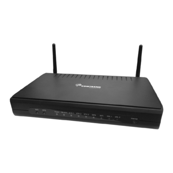
Chapter 1 Introduction The NexusLink 3112u Multi DSL Bonded Router is a single box solution for triple play applications. It features dual xDSL bonded ports that provide twice the xDSL bandwidth (ADSL2+ in both ATM/PTM modes and VDSL2 PTM 8a/8b/8c/8d/12a/12b/17a profiles) over comparable single-port models. With PTM mode supported, it can provide better performance than a regular ATM mode router. -
Page 8: Features
1.1 Features • Configuration backup and • Integrated 802.11n AP (802.11b/g backward-compatible) restoration • Automatically switches to • Up to 16 PVCs and Up to 8 PTM ADSL2+/VDSL2 according to the flows port setting of DSLAM • Supports bonded xDSL lines •... -
Page 9: Chapter 2 Installation
Chapter 2 Installation 2.1 Hardware Setup Follow the instructions below to complete the hardware setup. Non-stackable This device is not stackable – do not place units on top of each other, otherwise damage could occur. 2.2 Hardware Setup Follow the instructions below to complete the hardware setup. BACK PANEL The figure below shows the back panel of the device. - Page 10 NOTE: If pressed down for more than 60 seconds, the NexusLink 3112u will go into a firmware update state (CFE boot mode). The firmware can then be updated using an Internet browser pointed to the default IP address. GB ETH Port Use RJ45 straight through or crossover MDI/X cable to connect to Ethernet WAN.
-
Page 11: Led Indicators
2.3 LED Indicators The front panel LED indicators are shown below and explained in the following table. This information can be used to check the status of the device and its connections. Color Mode Function The device is powered up. Green The device is powered down. - Page 12 Flashing at 2 Hz with a 50% duty cycle when trying to detect carrier signal flashing at 4 Hz with a 50% duty cycle when the carrier has been detected and the modem is trying to train. The DSL2 link is established. The device is powered down.
-
Page 13: Chapter 3 Web User Interface
Chapter 3 Web User Interface This section describes how to access the device via the web user interface (WUI) using an Internet browser such as Internet Explorer (version 5.0 and later). 3.1 Default Settings The factory default settings of this device are summarized below. •... -
Page 14: Ip Configuration
3.2 IP Configuration DHCP MODE When the NexusLink 3112u powers up, the onboard DHCP server will switch on. Basically, the DHCP server issues and reserves IP addresses for LAN devices, such as your PC. To obtain an IP address from the DCHP server, follow the steps provided below. - Page 15 STATIC IP MODE In static IP mode, you assign IP settings to your PC manually. Follow these steps to configure your PC IP address to use subnet 192.168.1.x. NOTE: The following procedure assumes you are running Windows XP. However, the general steps involved are similar for most operating systems (OS).
-
Page 16: Login Procedure
3.3 Login Procedure Perform the following steps to login to the web user interface. NOTE: The default settings can be found in section 3.1 Default Settings. STEP 1: Start the Internet browser and enter the default IP address for the device in the Web address field. - Page 17 STEP 3: After successfully logging in for the first time, you will reach this screen. You can also reach this page by clicking on the following icon located at the top of the screen.
-
Page 18: Chapter 4 Device Information
Chapter 4 Device Information You can reach this page by clicking on the following icon located at the top of the screen. The web user interface window is divided into two frames, the main menu (at left) and the display screen (on the right). The main menu has several options and selecting each of these options opens a submenu with more selections. - Page 19 This screen shows hardware, software, IP settings and other related information.
-
Page 20: Wan
4.1 WAN Select WAN from the Device Info submenu to display the configured PVC(s). Heading Description Interface Name of the interface for WAN Description Name of the WAN connection Type Shows the connection type VlanMuxId Shows 802.1Q VLAN ID IPv6 Shows WAN IPv6 status IGMP Shows Internet Group Management Protocol (IGMP) -
Page 21: Statistics
4.2 Statistics This selection provides LAN, WAN, ATM and xDSL statistics. NOTE: These screens are updated automatically every 15 seconds. Click Reset Statistics to perform a manual update. 4.2.1 LAN Statistics This screen shows data traffic statistics for each LAN interface. Heading Description Interface... -
Page 22: Wan Service
4.2.2 WAN Service This screen shows data traffic statistics for each WAN interface. Heading Description Interface WAN interfaces Description WAN service label Received/Transmitted - Bytes Number of Bytes - Pkts Number of Packets - Errs Number of packets with errors - Drops Number of dropped packets... -
Page 23: Xtm Statistics
4.2.3 XTM Statistics The following figure shows ATM (Asynchronous Transfer Mode)/PTM (Packet Transfer Mode) statistics. XTM Interface Statistics Heading Description Port Number ATM PORT (0-3) In Octets Number of octets received over the interface Out Octets Number of octets transmitted over the interface In Packets Number of packets received over the interface Out Packets... -
Page 24: Xdsl Statistics
4.2.4 xDSL Statistics The xDSL Statistics screen displays information corresponding to the xDSL type. The two examples below (VDSL & ADSL) show this variation. VDSL... - Page 25 ADSL Click the Reset Statistics button to refresh this screen. Field Description Mode VDSL, VDSL2 Traffic Type ATM, PTM Status Lists the status of the DSL link...
- Page 26 Field Description Link Power State Link output power state. Line Coding (Trellis) Trellis On/Off SNR Margin (0.1 dB) Signal to Noise Ratio (SNR) margin Attenuation (0.1 dB) Estimate of average loop attenuation in the downstream direction. Output Power Total upstream output power (0.1 dBm) Attainable Rate (Kbps) The sync rate you would obtain.
- Page 27 xDSL BER TEST Click xDSL BER Test on the xDSL Statistics screen to test the Bit Error Rate (BER). A small pop-up window will open after the button is pressed, as shown below. Click Start to start the test or click Close to cancel the test. After the BER testing is complete, the pop-up window will display as follows.
- Page 28 xDSL TONE GRAPH Click Draw Tone Graph on the xDSL Statistics screen and a pop-up window will display the xDSL bits per tone status, as shown below.
-
Page 29: Route
4.3 Route Choose Route to display the routes that the NexusLink 3112u has found. Field Description Destination Destination network or destination host Gateway Next hop IP address Subnet Mask Subnet Mask of Destination Flag U: route is up !: reject route... -
Page 30: Arp
4.4 ARP Click ARP to display the ARP information. Field Description IP address Shows IP address of host pc Flags Complete, Incomplete, Permanent, or Publish HW Address Shows the MAC address of host pc Device Shows the connection interface 4.5 DHCP Click DHCP to display all DHCP Leases. - Page 31 Field Description IPv6 Address Shows IP address of device/host/PC MAC Address Shows the Ethernet MAC address of the device/host/PC Duration Shows leased time in hours Expires In Shows how much time is left for each DHCP Lease...
-
Page 32: Nat Session
4.6 NAT Session Click the “Show All” button to display the following. Field Description Source IP The source IP from which the NAT session is established Source Port The source port from which the NAT session is established Destination IP The IP which the NAT session was connected to Destination Port The port which the NAT session was connected to... -
Page 33: Igmp Proxy
4.7 IGMP Proxy Field Description Interface The Source interface from which the IGMP report was received The WAN interface from which the multicast traffic is received Groups The destination IGMP group address Member The Source IP from which the IGMP report was received Timeout The time remaining before the IGMP report expires... -
Page 34: Ipv6
4.8 IPv6 4.8.1 IPv6 Info Field Description Interface WAN interface with IPv6 enabled Status Connection status of the WAN interface Address IPv6 Address of the WAN interface Prefix Prefix received/configured on the WAN interface Device Link-local Address The CPE's LAN Address Default IPv6 Gateway The default WAN IPv6 gateway IPv6 DNS Server... -
Page 35: Ipv6 Neighbor
4.8.2 IPv6 Neighbor Field Description IPv6 Address Ipv6 address of the device(s) found Flags Status of the neighbor device HW Address MAC address of the neighbor device Device Interface from which the device is located... -
Page 36: Ipv6 Route
4.8.3 IPv6 Route Field Description Destination Destination IP Address Gateway Gateway address used for destination IP Metric Metric specified for gateway Interface Interface used for destination IP... -
Page 37: Network Map
4.9 Network Map The network map feature provides an illustration of connected devices on the router. The current wan status (firewall on/off) is displayed on the left side. Detailed information of PC/USB connected to the router is shown on the right side. -
Page 38: Wireless
4.10 Wireless 4.10.1 Station Info This page shows authenticated wireless stations and their status. Click the Refresh button to update the list of stations in the WLAN. Consult the table below for descriptions of each column heading. Field Description Lists the MAC address of all the stations. Associated Lists all the stations that are associated with the Access Point, along with the amount of time since packets were... -
Page 39: Site Survey
4.10.2 Site Survey The graph displays wireless APs found in your neighborhood by channel. -
Page 40: Chapter 5 Basic Setup
Chapter 5 Basic Setup You can reach this page by clicking on the following icon located at the top of the screen. This will bring you to the following screen. -
Page 41: Wan Setup
5.1 Wan Setup Add or remove ATM, PTM and ETH WAN interface connections here. Click Add to create a new ATM interface (see Appendix E - Connection Setup). NOTE: Up to 8 ATM interfaces can be created and saved in flash memory. To remove a connection, select its Remove column radio button and click Remove. -
Page 42: Wan Service Setup
5.1.1 WAN Service Setup This screen allows for the configuration of WAN interfaces. Click the Add button to create a new connection. For connections on ATM or ETH WAN interfaces see Appendix E - Connection Setup. To remove a connection, select its Remove column radio button and click Remove. Heading Description Interface... -
Page 43: Nat
5.2 NAT To display this option, NAT must be enabled in at least one PVC. NAT is not an available option in Bridge mode. 5.2.1 Virtual Servers Virtual Servers allow you to direct incoming traffic from the WAN side (identified by Protocol and External port) to the internal server with private IP addresses on the LAN side. - Page 44 Consult the table below for field and header descriptions. Field/Header Description Choose All Interface Virtual server rules will be created for all WAN interfaces. Choose One Interface Select a WAN interface from the drop-down box. Use Interface Select a Service User should select the service from the list.
-
Page 45: Port Triggering
5.2.2 Port Triggering Some applications require that specific ports in the firewall be opened for access by the remote parties. Port Triggers dynamically 'Open Ports' in the firewall when an application on the LAN initiates a TCP/UDP connection to a remote party using the 'Triggering Ports'. - Page 46 Field/Header Description Use Interface Select a WAN interface from the drop-down box. Select an Application User should select the application from the list. Custom Application User can enter the name of their choice. Trigger Port Start Enter the starting trigger port number (when you select custom application).
-
Page 47: Dmz Host
5.2.3 DMZ Host The DSL router will forward IP packets from the WAN that do not belong to any of the applications configured in the Virtual Servers table to the DMZ host computer. To Activate the DMZ host, enter the DMZ host IP address and click Save/Apply. To Deactivate the DMZ host, clear the IP address field and click Save/Apply. -
Page 48: Ip Address Map
5.2.4 IP Address Map Mapping Local IP (LAN IP) to some specified Public IP (WAN IP). Field/Header Description Rule The number of the rule Type Mapping type from local to public. Local Start IP The beginning of the local IP Local End IP The ending of the local IP Public Start IP... - Page 49 One to One: mapping one local IP to a specific public IP Many to one: mapping a range of local IP to a specific public IP Many to many(Overload): mapping a range of local IP to a different range of public IP Many to many(No Overload): mapping a range of local IP to a same range of public IP...
-
Page 50: Ipsec Alg
5.2.5 IPSEC ALG IPSEC ALG provides multiple VPN passthrough connection support, allowing different clients on LAN side to establish a secured IP Connection to the WAN server. To enable IPSEC ALG, tick the checkbox and click the Save button. -
Page 51: Sip Alg
5.2.6 SIP ALG This page allows you to enable / disable SIP ALG. -
Page 52: Lan
5.3 LAN Configure the LAN interface settings and then click Apply/Save. Consult the field descriptions below for more details. GroupName: Select an Interface Group. LAN INTERFACE IP Address: Enter the IP address for the LAN port. Subnet Mask: Enter the subnet mask for the LAN port. IGMP Snooping: Standard Mode: In standard mode, multicast traffic will flood to all bridge ports when no client subscribes to a multicast... - Page 53 Blocking Mode: In blocking mode, the multicast data traffic will be blocked and not flood to all bridge ports when there are no client subscriptions to any multicast group. Enable Enhanced IGMP: Enable by ticking the checkbox . IGMP packets between LAN ports will be blocked.
- Page 54 LAN INTERFACE To configure a secondary IP address, tick the checkbox outlined (in RED) below. IP Address: Enter the secondary IP address for the LAN port. Subnet Mask: Enter the secondary subnet mask for the LAN port. Ethernet Media Type: Configure auto negotiation, or enforce selected speed and duplex mode for the Ethernet ports.
-
Page 55: Lan Ipv6 Autoconfig
5.3.1 LAN IPv6 Autoconfig Configure the LAN interface settings and then click Save/Apply. Consult the field descriptions below for more details. - Page 56 LAN IPv6 Link-Local Address Configuration Heading Description EUI-64 Use EUI-64 algorithm to calculate link-local address from MAC address User Setting Use the Interface Identifier field to define a link-local address Static LAN IPv6 Address Configuration Heading Description Interface Address Configure static LAN IPv6 address and subnet prefix (prefix length is length required):...
- Page 57 To remove an entry, tick the corresponding checkbox in the Remove column and then click the Remove Entries button, as shown below. Heading Description Enable RADVD Enable use of router advertisement daemon RA interval Min(sec): Minimum time to send router advertisement RA interval Max(sec): Maximum time to send router advertisement Reachable Time(ms):...
-
Page 58: Static Ip Neighbor
5.3.2 Static IP Neighbor Click the Add button to display the following. Click Apply/Save to apply and save the settings. Heading Description IP Version The IP version used for the neighbor device IP Address Define the IP Address for the neighbor device MAC Address The MAC Address of the neighbor device Associated Interface... -
Page 59: Upnp
5.3.3 UPnP Select the checkbox provided and click Apply/Save to enable UPnP protocol. -
Page 60: Wireless
5.4 Wireless 5.4.1 Basic The Basic option allows you to configure basic features of the wireless LAN interface. Among other things, you can enable or disable the wireless LAN interface, hide the network from active scans, set the wireless network name (also known as SSID) and restrict the channel set based on country requirements. - Page 61 Option Description Hide Access Select Hide Access Point to protect the access point from detection Point by wireless active scans. To check AP status in Windows XP, open Network Connections from the start Menu and select View Available Network Connections. If the access point is hidden, it will not be listed there.
-
Page 62: Security
5.4.2 Security The following screen appears when Wireless Security is selected. The options shown here allow you to configure security features of the wireless LAN interface. Click Apply/Save to implement new configuration settings. WIRELESS SECURITY Setup requires that the user configure these settings using the Web User Interface (see the table below). - Page 63 The settings for WPA-PSK authentication are shown next. WEP Encryption This option specifies whether data sent over the network is encrypted. The same network key is used for data encryption and network authentication. Four network keys can be defined although only one can be used at any one time. Use the Current Network Key list box to select the appropriate network key.
- Page 64 hexadecimal numbers. A 128-bit key contains 13 ASCII characters or 26 hexadecimal numbers. Each key contains a 24-bit header (an initiation vector) which enables parallel decoding of multiple streams of encrypted data. Please see 6.13 for MAC Filter, Wireless Bridge and Advanced Wireless features.