Table of Contents
Advertisement
Quick Links
Advertisement
Table of Contents

Related Manuals for Teledyne Lecroy MS-250


Summary of Contents for Teledyne Lecroy MS-250
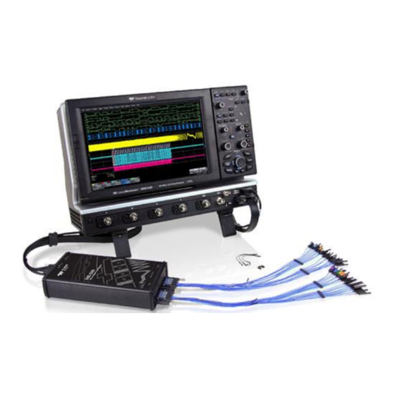
- Page 1 Operator's Manual MS-250 Mixed Signal Oscilloscope Option...
- Page 2 Administration Regulations. Export, reexport or diversion contrary to U.S. law is prohibited. Teledyne LeCroy is a registered trademark of Teledyne LeCroy, Inc. Other product or brand names are trademarks or requested trademarks of their respective holders. Information in this publication supersedes all earlier versions.
-
Page 3: Table Of Contents
Operator's Manual Contents Introduction ....................... 1 Technical Overview ..................... 1 Standard Hardware ..................... 3 Accessories ......................... 5 Connecting the Mixed Signal Device ..............7 Connecting the Unit ....................7 Connecting Digital Leads ..................10 Digital Logic Setup ....................11 Digital Group Setup ....................13 Displaying Digital Traces .................. - Page 4 MS-250 Mixed Signal Oscilloscope Option EAR99 technology subject to restrictions on copyrights page.
-
Page 5: Introduction
The MS-250 is ideally suited for embedded controller testing where there is a proliferation of analog signals coincident with digital signals. You can easily debug signals using standard oscilloscope tools such as cursors, measurement parameters, and zooming. - Page 6 While in SINGLE, NORMAL, or AUTO trigger mode, the MS-250 repeatedly samples each digital channel’s voltage level. If the voltage is above the threshold, the MS-250 stores a 1 in internal memory; if it is below threshold, a 0 is stored.
-
Page 7: Standard Hardware
Operator's Manual Standard Hardware The MS-250 is delivered with the following hardware in a carrying case: Part Description Mixed Signal Provides 18-channel digital acquisition and triggering. Accessory 16" Digital Connects the MS-250 to the device under test. The lead set Leadset terminates in a 25 mil pin socket. - Page 8 MS-250 Mixed Signal Oscilloscope Option Part Description Bus Cable 1.3 m cable connects the Mixed Signal Accessory to the main oscilloscope unit for timebase synchronization, cross- triggering and power. Includes USB 2.0 cable. 3" Flexible Lead for grounding individual digital inputs...
-
Page 9: Accessories
Operator's Manual Accessories You may purchase these optional accessories separately: Accessory Part Number Description Digital Leadset MSO-DLS-18 Additional 16" leadset for inputting lines D0-D17. This can be useful if you have more than one device under test and don't wish to disconnect/reconnect leads. - Page 10 MS-250 Mixed Signal Oscilloscope Option Accessory Part Number Description Small Gripper PK400-3 Small gripper probe set for 0.008 inch Probe Set (0.2 mm) pin pitch. Includes 10 probes with color-coded leads. Mictor Cable MSO-MICTOR Mictor Connection cable, 16" (40.64 cm),...
-
Page 11: Connecting The Mixed Signal Device
Operator's Manual Connecting the Mixed Signal Device Connecting the Unit To connect the Mixed Signal accessory to your oscilloscope: 1. Connect the Bus Cable to the LBUS connector on the oscilloscope. Be sure the head is turned so that the positioning wedge fits into the groove at the top of the connector. - Page 12 MS-250 Mixed Signal Oscilloscope Option 3. Connect the other end of the Bus Cable to the MS-250. Again, be sure to align the wedge and the groove. Fasten the thumb screws. 4. Connect the other end of the USB 2.0 Cable to the MS-250.
- Page 13 Operator's Manual 5. Connect the Digital Leadset to the Digital Inputs D0 – D17 connector on the opposite end of the MS-250 and fasten the thumb screws. NOTE: Each digital line has a ground connection for optimal performance. Two additional ground leads common to the whole leadset are also available.
-
Page 14: Connecting Digital Leads
The standard terminations on the digital leadset can be pushed directly onto 25-mil pins. MicroGrippers or NanoGrippers may also be used to probe the test circuit’s pins. Teledyne LeCroy provides a selection of small, medium, and large grippers for various pitch sizes. A more complete selection of adapter probes is available for most chips from Emulation Technology Inc.,... -
Page 15: Digital Logic Setup
Operator's Manual Digital Logic Setup Threshold Level The threshold level determines how the input signal is interpreted. Input voltages below the threshold are converted to 0/Low, while input voltages above it are converted to 1/High. Figure 2. Threshold level determines high-low of digital waveform. To set the logic threshold: 1. - Page 16 MS-250 Mixed Signal Oscilloscope Option Minimum Voltage (Hysteresis) You can define the minimum high and low voltage levels using the Hysteresis controls. Hysteresis can help prevent false determinations on variable signals. Hysteresis can be set up to 1.4 V above or below threshold.
-
Page 17: Digital Group Setup
Operator's Manual Digital Group Setup This procedure organizes the digital lines into groups, which correspond to buses. The lines within a single group can be displayed individually or collapsed into a Bus trace. You can set up a total of two, distinct groups: Digital1 and Digital2. Each group is designated by its own Digital setup dialog. -
Page 18: Displaying Digital Traces
MS-250 Mixed Signal Oscilloscope Option Displaying Digital Traces The Trace On checkbox is selected by default, so if you are connected to a live input, you should see digital traces appear as you add lines to the group. To turn off the trace display, clear Trace On. -
Page 19: Renaming Digital Lines
Operator's Manual Figure 5. Digital bus trace 1 division high starting at position 4. Store Display To store the entire group and display setup to an internal memory, touch the Store button at the far right of the dialog. You can recall this setup to the grid in the future by choosing Math >... -
Page 20: Digital Triggering
MS-250 Mixed Signal Oscilloscope Option Digital Triggering To access the Trigger setup dialogs, do one of the following: Choose Trigger > Trigger Setup from the menu bar • Press the front panel Trigger Setup button • Touch the Trigger descriptor box •... - Page 21 Operator's Manual by applying a hexadecimal value, while the remaining lines are disabled ("Don't Care"). If you have not yet set up digital groups, you can set a digital pattern line by line using the Logic method. All available lines remain active for selection.
- Page 22 MS-250 Mixed Signal Oscilloscope Option Analog Pattern 1. To add the analog pattern to the digital pattern, leave your digital pattern as is and skip to step 2. To create an analog-only pattern, touch Set All To... and select Don't Care.
-
Page 23: Setting Up A Serial Trigger
Operator's Manual Setting Up a Serial Trigger The Serial trigger type will appear on the Trigger dialog if you have installed serial data trigger and decode options. Select the Serial type, the desired Protocol, then Setup to open the serial trigger setup dialogs. Specific instructions for each protocol are in the trigger and decode manuals at teledynelecroy.com/support/techlib under Manuals >... -
Page 24: Reference
MS-250 Mixed Signal Oscilloscope Option Reference Certifications For the full list of current certifications, see the EC Declaration of Conformity shipped with your product. The probe is marked with this symbol to indicate that it complies with the applicable European Union requirements to Directives 2012/19/EU on Waste Electrical and Electronic Equipment (WEEE). -
Page 25: Returning A Product For Service
ATTN:<RMA code assigned by Teledyne LeCroy> • FRAGILE • 5. If returning a probe to a different country: contact Teledyne LeCroy Service for instructions on completing your import/export documents. Extended warranty, calibration and upgrade plans are available for purchase. Contact your Teledyne LeCroy sales representative to purchase a service plan. -
Page 26: Warranty
TRANSPORT PREPAID. The product is warranted for normal use and operation, within specifications, for a period of one year from shipment. Teledyne LeCroy will either repair or, at our option, replace any product returned to one of our authorized service centers within this period. However, in order to do this we... - Page 28 933079-00 Rev A December, 2020...