Table of Contents
Advertisement
Quick Links
Advertisement
Table of Contents

Related Manuals for Teledyne Lecroy HVD3000 Series


Summary of Contents for Teledyne Lecroy HVD3000 Series
- Page 1 Operator’s Manual HVD3000 Series High-Voltage Differential Probes...
- Page 3 HVD3000 Series High-Voltage Differential Probes Operator's Manual January, 2021...
- Page 4 Information contained herein is classified as EAR99 under the U.S. Export Administration Regulations. Export, reexport or diversion contrary to U.S. law is prohibited. Teledyne LeCroy is a trademark of Teledyne LeCroy, Inc. Other product or brand names are trademarks or requested trademarks of their respective holders. Information in this publication supersedes all earlier versions.
-
Page 5: Table Of Contents
Operator’s Manual Contents Introduction ..............................1 Safety ................................3 Voltage vs. Frequency Derating and Burn Limit ..................5 Voltage Derating for Accessories ......................8 HVD310xA Probes ............................9 HVD3206A Probes ............................. 15 HVD3220 Probes ............................19 HVD3605A Probes ............................. 23 Functional Test Procedure ........................ - Page 6 Teledyne LeCroy shall not be responsible for any defect, damage, or failure caused by any of the following: a) attempted repairs or installations by personnel other than Teledyne LeCroy representatives, b) improper connection to incompatible equipment, or c) use of non-Teledyne LeCroy supplies.
-
Page 7: Introduction
Operator’s Manual Introduction The HVD series high-voltage active differential probes are safe, easy-to-use, and ideally suited for power electronics applications where the reference potential is elevated from ground. The probes feature: Differential voltage measurement capability in high common-mode environments • (up to 6kVrms) Exceptional common-mode rejection ratio (CMRR) across a broad frequency range •... - Page 8 Maximum offset depends on the V/div setting and the oscilloscope model. In general, Teledyne LeCroy 12-bit High Resolution Oscilloscopes (HRO) and HD4096 High Definition Oscilloscopes (HDO) provide the most offset capability over the widest range of V/div settings.
-
Page 9: Safety
Operator’s Manual Safety To maintain the probe in a correct and safe condition, observe generally accepted safety procedures in addition to the precautions specified in this section. The overall safety of any system incorporating this product is the responsibility of the assembler of the system. Symbols These symbols appear on the probe and accessories or in this manual to alert you to important safety considerations. - Page 10 HVD3000 Series High-Voltage Differential Probes Keep fingers behind the finger guard of the probe accessories. Do not remove the probe's casing. Touching exposed connections may result in electric shock or burn. CAUTION. To prevent damage to the equipment: Use only as specified. The probe is intended to be used only with compatible Teledyne LeCroy instruments.
-
Page 11: Voltage Vs. Frequency Derating And Burn Limit
Operator’s Manual Voltage vs. Frequency Derating and Burn Limit The Maximum Input Voltage curve (solid line) shows the maximum voltage that can be applied to the probe inputs without risking damage to the probe. The lower Burn Limit curve (dashed line) shows the maximum voltage that can be applied to the probe inputs while the operator is handling the inputs. - Page 12 HVD3000 Series High-Voltage Differential Probes HVD3206A Derating and Burn Limit 10000 1000 1 Hz 10 Hz 100 Hz 1 kHz 10 kHz 100 kHz 1 MHz 10 MHz 100 MHz Vmax (Vrms) Burn Limit HVD3220 Derating and Burn Limit 10000...
- Page 13 Operator’s Manual HVD3605A Derating and Burn Limit 10000 1000 1 Hz 10 Hz 100 Hz 1 kHz 10 kHz 100 kHz 1 MHz 10 MHz 100 MHz Vmax (rms) Burn Limit EAR99 technology subject to restrictions on copyrights page.
-
Page 14: Voltage Derating For Accessories
HVD3000 Series High-Voltage Differential Probes Voltage Derating for Accessories Accessory Derated Max. Input Voltage for Combined Probe & Accessory (either input to ground)* Spade Terminals 1000 V CAT III Safety Alligator Clips 1000 V CAT III Plunger Alligator Clips 1000 V CAT III... -
Page 15: Hvd310Xa Probes
Operator’s Manual HVD310xA Probes HVD3102A/HVD3106A Probe Kit The probes are delivered with the following: Item Description Safety Rating* Spade Terminals Designed to connect to terminal strips, posts and Insulated 1000 V CAT III screws, the overall length is 63 mm (2.48 inches). 4 mm Banana (female) connector. - Page 16 HVD3000 Series High-Voltage Differential Probes Item Description Safety Rating* Plunger Pincer Clips Designed with a long, thin, flexible stem for Insulated 1000 V CAT II attaching to hard-to-reach test points, the entire body is fully insulated. The overall length is 161.6 mm (6.36 inch).
- Page 17 Operator’s Manual HVD310xA Specifications For the current specifications, see the product datasheet at teledynelecroy.com. Specifications are subject to change without notice. UARANTEED PECIFICATIONS HVD3102A HVD3106A HVD3106A-6M Bandwidth (probe only) 25 MHz 120 MHz 80 MHz Risetime 10-90 % 14 ns 2.9 ns 4.4 ns 80 dB @ 50 Hz...
- Page 18 HVD3000 Series High-Voltage Differential Probes HVD3102A Typical Bandwidth -1.0 -2.0 -3.0 -4.0 10 Hz 100 Hz 1 kHz 10 kHz 100 kHz 1 MHz 10 MHz 100 MHz 100X path 1000X path HVD3106A Typical Bandwidth -0.5 -1.0 -1.5 -2.0 10 Hz...
- Page 19 Operator’s Manual HVD3106A-6M Typical Bandwidth -1.0 -2.0 -3.0 -4.0 -5.0 -6.0 -7.0 -8.0 10 Hz 100 Hz 1 kHz 10 kHz 100 kHz 1 MHz 10 MHz 100 MHz 50X path 500X path HVD3102A Typical CMRR -100 10 Hz 100 Hz 1 kHz 10 kHz 100 kHz...
- Page 20 HVD3000 Series High-Voltage Differential Probes HVD3106A Typical CMRR -100 10 Hz 100 Hz 1 kHz 10 kHz 100 kHz 1 MHz 10 MHz 100 MHz 50X path 500X path HVD310xA Differential Input Impedance 100 M 10 M 100 k 10 k...
-
Page 21: Hvd3206A Probes
Operator’s Manual HVD3206A Probes HVD3206A Probe Kit The probes are delivered with the following: Item Description Safety Rating* 2 kV Rated Plunger The clip is designed to securely grasp thick wires, 2000 V (DC+Peak AC) CAT I** Alligator Clips cables, ground leads, rails, and screw heads. The 1000 Vrms CAT III overall length is 130 mm (5.1 inches);... - Page 22 HVD3000 Series High-Voltage Differential Probes HVD3206A Specifications For the current specifications, see the product datasheet at teledynelecroy.com. Specifications are subject to change without notice. UARANTEED PECIFICATIONS HVD3206A HVD3206A-6M Bandwidth (probe only) 120 MHz 80 MHz Risetime 10-90% 2.9 ns 4.4 ns...
- Page 23 Operator’s Manual HVD3206A Typical Bandwidth -0.5 -1.0 -1.5 -2.0 10 Hz 100 Hz 1 kHz 10 kHz 100 kHz 1 MHz 10 MHz 100 MHz 50X path 500X path HVD3206A-6M Typical Bandwidth -1.0 -2.0 -3.0 -4.0 -5.0 -6.0 -7.0 -8.0 10 Hz 100 Hz 1 kHz...
- Page 24 HVD3000 Series High-Voltage Differential Probes HVD3206A Typical CMRR -100 10 Hz 100 Hz 1 kHz 10 kHz 100 kHz 1 MHz 10 MHz 100 MHz 50X path 500X path HVD3206A Differential Input Impedance 100 M 10 M 100 k 10 k...
-
Page 25: Hvd3220 Probes
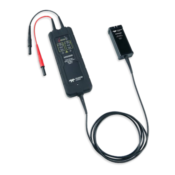
Operator’s Manual HVD3220 Probes HVD3220 Probe Kit The probes are delivered with the following: Item Description Safety Rating* 2 kV Rated Plunger The clip is designed to securely grasp thick wires, 2000 V (DC+Peak AC) CAT I** Alligator Clips cables, ground leads, rails, and screw heads. The 1000 Vrms CAT III overall length is 130 mm (5.1 inches);... - Page 26 HVD3000 Series High-Voltage Differential Probes HVD3220 Specifications For the current specifications, see the product datasheet at teledynelecroy.com. Specifications are subject to change without notice. UARANTEED PECIFICATIONS HVD3220 Bandwidth (probe only) 400 MHz Risetime 10-90% 875 ps 80 dB @ DC...
- Page 27 Operator’s Manual HVD3220 Typical Bandwidth -2.0 -4.0 -6.0 -8.0 10 Hz 100 Hz 1 kHz 10 kHz 100 kHz 1 MHz 10 MHz 100 MHz 50X path 100X path 250X path 500X path HVD3220 Typical CMRR -100 10 Hz 100 Hz 1 kHz 10 kHz 100 kHz...
- Page 28 HVD3000 Series High-Voltage Differential Probes HVD3220 Differential Input Impedance 100 M 10 M 100 k 10 k 10 Hz 100 Hz 1 kHz 10 kHz 100 kHz 1 MHz 10 MHz 100 MHz EAR99 technology subject to restrictions on copyrights page.
-
Page 29: Hvd3605A Probes
Operator’s Manual HVD3605A Probes HVD3605A Probe Kit The probes are delivered with the following: Item Description Safety Rating* 6 kV Rated Designed to reliably grip large components, such 6000 V CAT I** Alligator Clips as bus bars and large bolts, the overall length is 1000 Vrms CAT III 116 mm (4.57 inches) and the jaw opens to 1500 Vdc CAT III... - Page 30 HVD3000 Series High-Voltage Differential Probes HVD3605A Specifications For the current specifications, see the product datasheet at teledynelecroy.com. Specifications are subject to change without notice. UARANTEED PECIFICATIONS HVD3605A Bandwidth (probe only) 100 MHz Risetime 10-90% 4.3 ns 80 dB @ 50 Hz...
- Page 31 Operator’s Manual HVD3605A Typical Bandwidth -1.0 -2.0 -3.0 -4.0 10 Hz 100 Hz 1 kHz 10 kHz 100 kHz 1 MHz 10 MHz 100 MHz HVD3605A Typical CMRR -100 10 Hz 100 Hz 1 kHz 10 kHz 100 kHz 1 MHz 10 MHz 100 MHz 200X path...
- Page 32 HVD3000 Series High-Voltage Differential Probes HVD3605A Differential Input Impedance 100 M 10 M 100 k 10 k 1 Hz 10 Hz 100 Hz 1 kHz 10 kHz 100 kHz 1 MHz 10 MHz 100 MHz EAR99 technology subject to restrictions on copyrights page.
-
Page 33: Functional Test Procedure
Operator’s Manual Functional Test Procedure Perform this procedure to confirm the basic operation of an HVD3000 series probe or to aid in determining the source of a problem, rather than to verify the accuracy of the probe. You can perform the Functional Test without removing the probe covers. -
Page 34: Performance Verification Procedure
This procedure can be used to verify the warranted characteristics of an HVD series probe. If the product does not meet specifications, it should be returned to a Teledyne LeCroy service center. As there are no user accessible adjustments, there is no adjustment procedure. -
Page 35: Preliminary Procedure
Operator’s Manual Preliminary Procedure 1. Connect the probe under test to the female end of the ProBus Extension Cable. Connect the male end of the ProBus Extension Cable to channel 1 (C1) of the oscilloscope. 2. Turn on the oscilloscope and allow at least 30 minutes warm-up time before performing the Certification Procedure. - Page 36 HVD3000 Series High-Voltage Differential Probes 8. Connect the insulated banana plug adapter to the function generator. 9. Using the insulated banana couplers, connect the positive lead (red) of the probe under test to the positive output of the BNC-to-banana plug adapter and the negative lead (black) to the negative or return output.
-
Page 37: Checking Probe Attenuation In Maui Automation Browser
This completes the Performance Verification Procedure. Complete and file the Test Record as required to support your internal calibration procedure. If the criteria in steps 14, 19 or 20 are not met, contact your local Teledyne LeCroy service center. Checking Probe Attenuation in MAUI Automation Browser Probe attenuation and other values can be found by using the MAUI Automation Browser application that is installed with the oscilloscope firmware. -
Page 38: Hvd
HVD3000 Series High-Voltage Differential Probes HVD________ Test Record Serial Number:____________________________________________________ Asset / Tracking Number: _________________________________________ Date:______________________________________________________________ Technician:________________________________________________________ Equipment Model Serial Number Calibration Date Oscilloscope Digital Multimeter Function Generator* * In this Performance Verification Procedure, the function generator is used for making relative measurements. The output of the generator is measured with a DMM or oscilloscope. -
Page 39: Operation
Operator’s Manual Operation Connecting to the Test Instrument HVD series probes have been designed for use with Teledyne LeCroy oscilloscopes equipped with the ProBus interface. When you attach the probe to the oscilloscope’s input connector, the instrument will: Recognize the probe •... -
Page 40: Operating With An Oscilloscope
Operating with an Oscilloscope When the probe is connected to a Teledyne LeCroy oscilloscope, the displayed scale factor and measurement values will be adjusted to account for the effective gain of the probe. - Page 41 Operator’s Manual The total usable offset of the oscilloscope and probe system is a function of the oscilloscope V/div setting and offset at that V/div setting, and the probe attenuation and offset at that attenuation setting. Total maximum offset may be calculated as: Oscilloscope Front End V/Div = (Probe and Oscilloscope) V/Div ÷...
- Page 42 HVD3000 Series High-Voltage Differential Probes off the screen, preventing measurement errors. There are times, however, when it is convenient to use AC coupling to remove the DC component of the measured signal from the measurement. Selecting AC10MΩ uses the scope AC coupling at the probe output to remove any steady state value from the displayed voltage.
- Page 43 Operator’s Manual Overload Indicator An indication will appear in the oscilloscope message bar when the differential or common mode voltages are beyond the operating ranges of the probe. Note that the warning message below may trigger before any saturation occurs. It is designed to guarantee that the system will not fail to indicate an overload.
-
Page 44: Maintenance
Service Strategy HVD series probes utilize fine-pitch surface mount devices. It is, therefore, impractical to attempt repair in the field. Defective probes must be returned to a Teledyne LeCroy service facility for diagnosis and exchange. CAUTION. Do not remove the covers. Refer all servicing to qualified personnel. A defective probe under warranty will be replaced with a factory refurbished probe. -
Page 45: Replacement Probe Accessory Kit
• FRAGILE • 5. If returning a product to a different country: contact Teledyne LeCroy Service for instructions on completing your import/export documents. Extended warranty, calibration and upgrade plans are available for purchase. Contact your Teledyne LeCroy sales representative to purchase a service plan. -
Page 46: Reference
HVD3000 Series High-Voltage Differential Probes Reference Technical Support Registered users can contact their local Teledyne LeCroy service center at the number listed on our website. For a complete list of offices by country, including our sales & distribution partners, visit: teledynelecroy.com/support/contact... -
Page 47: Certifications
Operator’s Manual Certifications Teledyne LeCroy certifies compliance to the following standards as of the time of publication. Please see the EC Declaration of Conformity certificate shipped with your product for current certifications. EMC Compliance EC D - EMC ECLARATION OF ONFORMITY The probe meets the intent of EC Directive 2014/30/EU for Electromagnetic Compatibility. - Page 48 HVD3000 Series High-Voltage Differential Probes Safety Compliance EC D ECLARATION OF ONFORMITY OLTAGE The probe meets the intent of EC Directive 2014/35/EU for Product Safety. Compliance was demonstrated to the following specifications as listed in the Official Journal of the...
-
Page 49: Common Mode Rejection Ratio
Operator’s Manual Common Mode Rejection Ratio The ideal differential probe/amplifier would sense and amplify only the differential mode voltage component and reject the entire common mode voltage component. Real differential amplifiers are not perfect, and a small portion of the common mode voltage component appears at the output. -
Page 50: Differential Mode Range And Common Mode Range
HVD3000 Series High-Voltage Differential Probes Differential Mode Range and Common Mode Range Differential Mode range is the maximum signal that can be applied between the + and - inputs without overloading the amplifier, which otherwise would result in clipping or distorting of the waveform measured by the oscilloscope. - Page 52 932762-00 Rev A January, 2021...