Advertisement
Quick Links
Installation & Operation Guide
Thank you for purchasing the Franklin Control
Systems Single Phase Building Automation Starter!
Please read this manual thoroughly to ensure
safe installation and proper operation.
Precautions
To prevent injury and property damage, follow these instructions.
Failure to adhere to installation/operation procedures and all
applicable codes may result in hazards as indicated by warning
codes outlined below:
DANGER
indicates an imminently hazardous situation which, if not avoided, will
result in death or serious injury. This signal word is to be limited to the
most extreme situations.
WARNING
indicates a potentially hazardous situation which, if not avoided, could
result in death or serious injury.
CAUTION
indicates a potentially hazardous situation which, if not avoided, may
result in minor or moderate injury. It may also be used to alert against
unsafe practices.
This is the safety alert symbol. Read and follow instructions carefully to
avoid a dangerous situation.
This symbol alerts the user to the presence of "dangerous voltage"
inside the product that might cause harm or electrical shock.
Safety Instructions
DANGER
Equipment starts automatically. Lockout/tagout before servicing.
CAUTION
As with all electrical products, read manual thoroughly. Only qualified,
expert personnel should perform maintenance and installation. Contact the
nearest authorized service facility for examination, repair, or adjustment.
Do not disassemble or repair unit unless described in this manual; death
or injury to electrical shock or fire hazard may result. Specifications and
manual data subject to change. Consult factory for additional information.
HAZARDOUS VOLTAGE
• Disconnect and lock out all power before installing or servicing equipment.
• This equipment may require locking out multiple power sources prior to service
• Install and wire in accordance with all applicable local & national electrical and
construction codes
www.franklin-controls.com | 800.962.3787 | 22985 NW Evergreen Pkwy Hillsboro, OR 97124
Updated 9.11.14
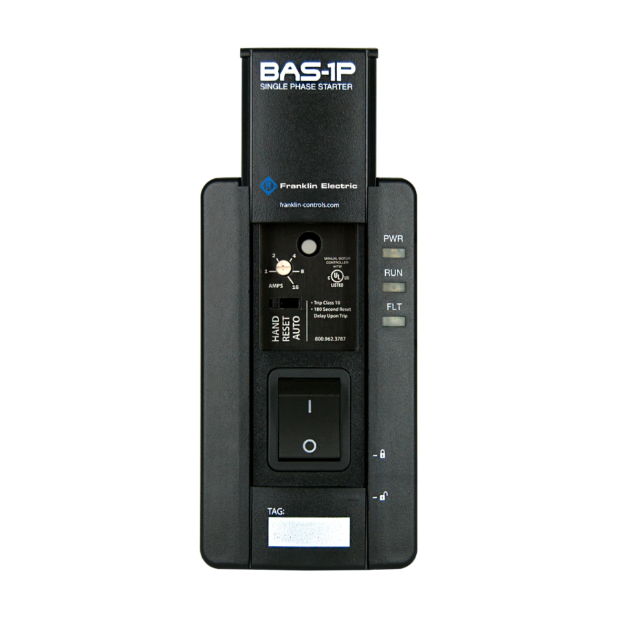
Installation
FAILURE TO FOLLOW THESE INSTRUCTIONS MAY RESULT IN DEATH OR
SERIOUS INJURY
Mounting
Mount the starter on a minimum 14 cu-in single gang junction box. To access
mounting holes, slide upper and lower covers to the open position.
(See Figure 1)
Using provided mounting screws (6-32 x 7/8"), attach starter housing to junction
box (once appropriate wiring has been completed).
WARNING
•
materials. Contact arcing can induce explosion or fire.
• Install starter in UL Type 1 (NEMA 1) appropriate locations only. Safe mounting
requires a dry, protected environment.
• The BAS-1P is rated for maximum ambient temperature of 40°C
• Do not allow any metal shavings or debris from installation to enter enclosure.
Main Power Wiring
Wire main power input and output to the appropriate 12AWG wire leads utilizing
properly sized wire nuts. Use only copper conductors rated at least 60°C.
Maintain proper clearances and verify that no possibility of an electrical short
exists between the power conductors or enclosure. Ensure that wires are not
under stress and all insulation is intact.
Low Voltage Wiring
Automation system control wiring should be run in a separate conduit. The
control terminals accept 26~14AWG wire torqued to 3.5 in-lb.
1Ø AC Input 50/60 Hz
L1
L2/N
Fault
Output
Status
Output
T1
T2
M
© Copyright 2017 Franklin Control Systems
Figure 1
Voltage Input
Auto Run
12-120VAC/DC
Input
Normally Open
Input
Dry Input
Auto Run
Advertisement

Related Manuals for Franklin BAS-1P

Summary of Contents for Franklin BAS-1P
- Page 1 • Install starter in UL Type 1 (NEMA 1) appropriate locations only. Safe mounting requires a dry, protected environment. • The BAS-1P is rated for maximum ambient temperature of 40°C To prevent injury and property damage, follow these instructions. • Do not allow any metal shavings or debris from installation to enter enclosure.
- Page 2 FAULT (FLT) - Overload Trip Overload Adjustment The BAS-1P indicates a fault condition by flashing the red FAULT Operation Mode Selector LED which will remain constant in the event of a fault trip. The LED will also flash if a RESET attempt is made during the 180 second...