
Related Manuals for Vaisala CARBOCAP GMW90 Series


Summary of Contents for Vaisala CARBOCAP GMW90 Series
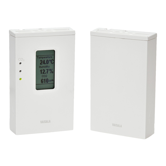
- Page 1 USER'S GUIDE Vaisala CARBOCAP® Carbon Dioxide, Temperature, and Humidity Transmitters GMW90 Series M211659EN-C...
- Page 2 This manual does not create any legally binding obligations for Vaisala towards customers or end users. All legally binding obligations and agreements are included exclusively in the applicable supply contract or the General Conditions of Sale and General Conditions of Service of Vaisala.
-
Page 3: Table Of Contents
Installing the Mounting Base ..........25 Wiring ..................25 Wiring GMW93R/RA ............27 Wiring GMW93 ..............27 Wiring GMW94R ..............28 Wiring GMW94 ..............28 Wiring GMW95 ..............29 Connecting Several Transmitters on Same RS-485 Line ..............29 VAISALA _________________________________________________________________________ 1... - Page 4 User's Guide _______________________________________________________________________ Connecting a Common AC Power Supply to Several Transmitters ................. 30 CHAPTER 4 OPERATION ....................31 Display ..................31 Startup Screens ..............31 Measurement Screen ............32 Indicators on the Display ............. 33 Service Port ................33 Connecting With an MI70 Indicator ........
- Page 5 Technical Support ..............79 CHAPTER 7 TECHNICAL DATA ..................80 Specifications ................. 80 Spare Parts and Accessories ..........82 Dimensions in mm ..............83 APPENDIX A BACNET REFERENCE ................84 BACnet Protocol Implementation Conformance Statement ................84 VAISALA _________________________________________________________________________ 3...
- Page 6 User's Guide _______________________________________________________________________ Transmitter Models and Objects ........... 86 Device Object ................87 Carbon Dioxide Object ............89 Temperature Object ..............90 Relative Humidity Object ............91 Calculated Humidity Objects ..........92 Operation Pressure Object ............ 93 Operation Altitude Object ............94 BIBBs Supported ..............
- Page 7 Replacing the HTM10 Module ..........72 Figure 31 DIP Switch Factory Reset (GMW93/94) ........77 Figure 32 DIP Switch Factory Reset (GMW95) ........77 Figure 33 GMW90 Series Dimensions ............. 83 Figure 34 Dimensions of the Mounting Base ........... 83 VAISALA _________________________________________________________________________ 5...
- Page 8 User's Guide _______________________________________________________________________ List of Tables Table 1 Manual Revisions ............... 8 Table 2 Related Manuals ................. 8 Table 3 Applicable Patents ..............10 Table 4 GMW90 Series Transmitters ............ 13 Table 5 Parameters Supported by GMW90 Series ....... 14 Table 6 Serial Interface Settings ............
-
Page 9: Chapter 1 General Information
- Chapter 7, Technical Data, provides the technical data of the GMW90 series transmitters. - Appendix A, BACnet Reference, describes the BACnet protocol implementation of the GMW90 series digital transmitters. - Appendix B, Modbus Reference, describes the Modbus protocol implementation of the GMW90 series digital transmitters. VAISALA _________________________________________________________________________ 7... -
Page 10: Version Information
User's Guide _______________________________________________________________________ Version Information Table 1 Manual Revisions Manual Code Description M211659EN-C April 2016. This manual. Updated sections: Transmitter Parts on page 15. Configuration of Analog Output Models on page 19. Selecting Location on page 24. Effect of Pressure on CO Measurement on page Replacing the GM10 Module on page 70. -
Page 11: Safety
ESD Protection Electrostatic Discharge (ESD) can cause immediate or latent damage to electronic circuits. Vaisala products are adequately protected against ESD for their intended use. It is possible to damage the product, however, by delivering electrostatic discharges when touching, removing, or inserting any objects inside the equipment housing. -
Page 12: Recycling
User's Guide _______________________________________________________________________ Recycling Recycle all applicable material. Dispose of the unit according to statutory regulations. Do not dispose of with regular household refuse. Regulatory Compliances GMW90 series transmitters comply with the following performance and environmental test standards: - EMC Directive Conformity is shown by compliance with the following standards: - EN 61326-1: Electrical equipment for measurement, control, and laboratory use –... -
Page 13: Trademarks
All other trademarks are the property of their respective owners. Software License This product contains software developed by Vaisala. Use of the software is governed by license terms and conditions included in the applicable supply contract or, in the absence of separate license terms and conditions, by the General License Conditions of Vaisala Group. -
Page 14: Chapter 2 Product Overview
User's Guide _______________________________________________________________________ CHAPTER 2 PRODUCT OVERVIEW This chapter introduces the GMW90 series transmitters. Introduction to GMW90 Series GMW90 series transmitters are wall-mount transmitters for building automation applications. All GMW90 series transmitters measure carbon dioxide (CO ) and temperature (T), and some models also include humidity measurement. -
Page 15: Gmw90 Series Transmitters
Digital temperature (Modbus/BACnet) GMW95RD , humidity, Digital temperature (Modbus/BACnet) GMW90* , temperature Configurable Optional Optional (digital or analog) GMW90R* , humidity, Configurable Optional Optional temperature (digital or analog) * Factory configurable model. See order form for details. VAISALA ________________________________________________________________________ 13... -
Page 16: Output Parameters Explained
User's Guide _______________________________________________________________________ Output Parameters Explained Table 5 Parameters Supported by GMW90 Series Parameter Symbol Unit(s) Description Carbon Concentration of carbon dioxide dioxide gas (CO Temperature T °C Temperature in Celsius or °F Fahrenheit scale. Relative Ratio of the partial pressure of humidity water vapor in the air to the saturation vapor pressure of air... -
Page 17: Transmitter Parts
Red LED (top): lit between 1200 ... 5000 ppm CO blinking at > 5000 ppm CO 9 = Type label. 10 = Holes for indicator LEDs (only in models with LED option). 11 = Grip for slide. VAISALA ________________________________________________________________________ 15... -
Page 18: Figure 3 Opening The Transmitter
User's Guide _______________________________________________________________________ 1201-005 Figure 3 Opening the Transmitter 1 = Push tab down with a screwdriver to open the transmitter. To open, use a screwdriver to push down the tab that holds the transmitter cover and mounting base together. Pull the mounting base away from the cover, starting from the top. -
Page 19: Figure 4 Transmitter Parts - Inside
DIP switch bank for transmitter address. 13 = Grip for slide. 14 = TM10 module (measures temperature only) or HTM10 module (measures humidity and temperature). ® 15 = HUMICAP sensor (on models with humidity measurement). VAISALA ________________________________________________________________________ 17... -
Page 20: Decorative Cover Option
User's Guide _______________________________________________________________________ Decorative Cover Option The decorative cover is an installation accessory for HMW90 and GMW90 series transmitters that can be used to hide the transmitter from view. The cover material is transparent polycarbonate, but the idea is to customize it to match the wall the transmitter is on. -
Page 21: Chapter 3 Installation
If you have used the AOVER command to configure the behavior of analog outputs when the measured value is outside the scaled output range, your AOVER configuration remains even in DIP switch configuration mode. See Set Output Clipping and Error Limit on page 45. VAISALA ________________________________________________________________________ 19... -
Page 22: Dip Switches Of Analog Output Models
User's Guide _______________________________________________________________________ DIP Switches of Analog Output Models 1 2 3 4 5 6 7 8 1 2 3 4 5 6 7 8 GMW93 GMW94 1402-027 Figure 6 DIP Switch Settings of Analog Output Models Position Setting Non-metric Non-metric units (°F). -
Page 23: Changing Between Dip And Custom Configuration
- Some configuration actions can be done using the BACnet and Modbus protocols. See the following appendices for protocol implementation details: - Appendix A, BACnet Reference, on page 84. - Appendix B, Modbus Reference, on page 97. VAISALA ________________________________________________________________________ 21... -
Page 24: Dip Switches Of Digital Output Models
User's Guide _______________________________________________________________________ DIP Switches of Digital Output Models Parity Even Modbus Non-Metric 128 64 32 16 8 1 2 3 4 5 6 7 8 2 3 4 5 6 7 8 Baud Address Rate Metric (Binary Weighting) BACnet Parity None 1209-016 Figure 7... -
Page 25: Addressing With Bacnet Protocol
BACnet MS/TP MAC address range is 0 … 255. The transmitter is a BACnet MS/TP master if address is below 128. Otherwise the transmitter is a slave. Addressing with Modbus Protocol Transmitter is always a Modbus slave. MAC address range for Modbus slaves is 1 … 247. VAISALA ________________________________________________________________________ 23... -
Page 26: Selecting Location
User's Guide _______________________________________________________________________ Selecting Location The conditions at the location should represent well the area of interest. Do not install the transmitter on the ceiling. Avoid placing the transmitter near heat and moisture sources, close to the discharge of the supply air ducts, and in direct sunlight. -
Page 27: Installing The Mounting Base
< Ø 5 mm cable, and route it from the left side of the mounting base. See Figure 12 on page 26. After completing the wiring, connect the transmitter body over the mounting base. Note that mounting bases are model-specific. WARNING Connect only de-energized wires. VAISALA ________________________________________________________________________ 25... -
Page 28: Figure 11 Wiring From Behind (Recommended)
User's Guide _______________________________________________________________________ 1310-044 Figure 11 Wiring from Behind (Recommended) 1310-045 Figure 12 Wiring from Above 26 ___________________________________________________________________ M211659EN-C... -
Page 29: Wiring Gmw93R/Ra
GMW93 is wired in the same way as GMW93R/RA, except for the humidity output that is not present: Power supply 18 ... 35 VDC or 24 VAC ±20% = 10 kΩ min. 1402-030 Figure 15 Wiring GMW93 VAISALA ________________________________________________________________________ 27... -
Page 30: Wiring Gmw94R
User's Guide _______________________________________________________________________ Wiring GMW94R -Vs terminal is internally connected to GND terminal. Power supply 18 ... 35 VDC or 24 VAC ±20% = 0 ... 600 Ω 1402-034 Figure 16 Wiring GMW94R Wiring GMW94 GMW94 is wired in the same way as GMW94R, except for the humidity output that is not present: Power supply 18 ... -
Page 31: Wiring Gmw95
Connect the cable shield to ground on the building controller side. Building controller Transmitter Transmitter Transmitter Power supply RS-485: BACnet or MODBUS master SHIELD Shld Shld Shld Set RS-485 Connect shield on controller side termination jumper 1209-015 Figure 19 Several Transmitters on Same RS-485 Line VAISALA ________________________________________________________________________ 29... -
Page 32: Connecting A Common Ac Power Supply To Several Transmitters
User's Guide _______________________________________________________________________ Connecting a Common AC Power Supply to Several Transmitters If you are connecting a common 24 VAC power supply to several transmitters, make sure to connect the same terminal to +Vs and –Vs on all transmitters. This will avoid a short-circuit through the shared common line at the controller;... -
Page 33: Chapter 4 Operation
The last screen shows the currently configured pressure compensation setting. 1310-049, 1310-047 Figure 21 GMW95R Startup Screens After the startup screens the transmitter shows the measurement screen. It shows the measured parameters and currently active indicators. VAISALA ________________________________________________________________________ 31... -
Page 34: Measurement Screen
User's Guide _______________________________________________________________________ Measurement Screen Measurement screen shows the measured parameters and currently active indicators. 1310-040 Figure 22 Measurement Screen – Normal Operation If there is a problem with measurement, affected readings are replaced with stars. The alarm indicator and an error message will also appear on the screen. -
Page 35: Indicators On The Display
Service Port You can connect to the service port on the GMW90 series transmitters using a computer or an MI70 indicator. The MI70 indicator is the hand- held display device that is included with, for example, the Vaisala ® CARBOCAP Hand-Held Carbon Dioxide Meter GM70. -
Page 36: Connecting With A Computer
When connecting using a computer, use the Vaisala USB cable (Vaisala order code 219690) and a suitable terminal application: - If you have not used the Vaisala USB cable before, install the driver before attempting to use the cable. Refer to section Installing the Driver for the USB Service Cable on page 34 for detailed instructions. -
Page 37: Terminal Application Settings
Serial line to connect to field. Note: You can check which port the USB cable is using with the Vaisala USB Instrument Finder program that has been installed in the Windows Start menu. Check that the other serial settings are correct for your connection, and change if necessary. -
Page 38: Figure 24 Putty Terminal Application
User's Guide _______________________________________________________________________ 0807-004 Figure 24 PuTTY Terminal Application 36 ___________________________________________________________________ M211659EN-C... -
Page 39: List Of Serial Commands
Calibrate and adjust RH measurement. Calibrate and adjust T measurement. CTEXT Show or set calibration information. DSEL Select parameters to display on screen. FRESTORE Restore transmitter to factory settings. TRAF Show or set CO indicator LED parameters. VAISALA ________________________________________________________________________ 37... -
Page 40: Transmitter Information
User's Guide _______________________________________________________________________ Transmitter Information Show Transmitter Information The ? command outputs a listing of device information. ?<cr> Example: >? Device : GMW95R SW version : 1.1.28.5849 SNUM : H2930002 HTM10 module information Software version : 0.11.1 SNUM : H2950107 GM10 module information Software version : 1.1.0... -
Page 41: Show Transmitter Status
: 127 (7Fh) Node type : Master Baud setting : Auto Current baudrate : 19200 8N1 Baudrate locked : No Baud detection interval: 10 s : Communication enabled Valid frames Invalid frames Unwanted frames Lost tokens Failed TX VAISALA ________________________________________________________________________ 39... - Page 42 User's Guide _______________________________________________________________________ Example (display full status): >status Device Name : GMW95R Copyright : Copyright Vaisala Oyj 2013 SW Name : XM90 SW Model : XM9x SW version : 1.1.28.5849 Serial number : H2930002 Address SUB FUNCTIONS * Serial Port (COM1) *...
-
Page 43: Show Measured Parameters
CALCS command also lists all humidity parameters, even if your transmitter model does not measure humidity. Show Command Help To see a short description of an individual command, issue the command with a question mark as a parameter. Example: >calcs ? Display measured quantities VAISALA ________________________________________________________________________ 41... -
Page 44: Show Command List
User's Guide _______________________________________________________________________ Show Command List Use the HELP command to list the currently available serial commands. If the PASS command has not been used, only the basic serial commands are available. HELP<cr> Example (basic serial commands from a transmitter model with analog outputs, advanced commands are not enabled): >help CALCS... -
Page 45: Select Units
AMODE [channel lo_value hi_value error_value]<cr> where channel = Analog output channel, 1 ... 3. lo_value = Low limit of the channel. hi_value = High limit of the channel. error_value = Error value of the channel. VAISALA ________________________________________________________________________ 43... -
Page 46: Set Analog Output Scaling
User's Guide _______________________________________________________________________ Example (show current configuration): >pass 9000 >amode Aout 1 range (mA) : 4.00 ... 20.00 (error: 3.60) Aout 2 range (mA) : 4.00 ... 20.00 (error: 3.60) Aout 3 range (mA) : 4.00 ... 20.00 (error: 3.60) Example (set channel 1 to 0 ... -
Page 47: Set Output Clipping And Error Limit
The parameter for channel 3 is CO2, with standard output range 0 ... 5 V and scaling 0 ... 2000 ppm. Error state is 5.5 V, which is set immediately when the measured value is outside the scaled output range. VAISALA ________________________________________________________________________ 45... - Page 48 User's Guide _______________________________________________________________________ Now give the following AOVER command: >aover 3 5 10 Aout 3 clipping : 5.00 % Aout 3 error limit : 10.00 % Channel 3 now behaves like this: - Clipping is now set to 5%, meaning the output is allowed to vary between 0 ...
-
Page 49: Display Settings
= Third parameter to show on the screen. Available parameters are the same as for Q1. Example (show currently displayed parameters): >pass 9000 >dsel Quant 1 : RH Quant 2 Quant 3 : CO2 Example (change display to only show CO2): >dsel CO2 VAISALA ________________________________________________________________________ 47... -
Page 50: Serial Line Output Commands
User's Guide _______________________________________________________________________ Serial Line Output Commands Start Measurement Output Use the R command to start the continuous outputting of measurement values as an ASCII text string to the serial line. The format of the measurement message is set with the FORM command. R<cr>... -
Page 51: Set Output Interval
= time unit = "S", "MIN", or "H" The shortest output interval (with n = 0) outputs the measurement messages as quickly as the transmitter produces them, without additional delay. Example: >intv 1 min Output interval : 1 min VAISALA ________________________________________________________________________ 49... -
Page 52: Set Output Format
User's Guide _______________________________________________________________________ Set Output Format Use the serial line command FORM to change the measurement message sent by the transmitter on the service port. You can freely define the output message to include the desired parameters, formatting options, text strings, and additional fields. FORM [modifier string]<cr>... -
Page 53: Table 9 Form Command Parameters
Modulus-65536 checksum of message sent so far, ASCII encoded hexadecimal notation NMEA xor-checksum of message sent so far, ASCII encoded hexadecimal notation NOTE When entering modifiers, you can also use the backslash character “\” instead of the hash “#”. VAISALA ________________________________________________________________________ 51... -
Page 54: Serial Line Settings
User's Guide _______________________________________________________________________ Serial Line Settings Set Remote Echo Use the ECHO command to enable or disable remote echo by the transmitter. ECHO [on/off]<cr> Example: >echo on Echo : ON Set Serial Line Turnaround Delay With the SDELAY command you can set the turnaround delay of the transmitter (time waited before replying to an incoming message) or view the currently set delay value. -
Page 55: Calibration And Adjustment Commands
Adjustment on page 64. Show Current CO Adjustment In addition to the user-adjustable offset and gain values, the CCO2 command displays diagnostic information that may be useful to Vaisala Helpdesk if there is a problem with the adjustment. CCO2<cr> Example: >pass 9000... -
Page 56: 1-Point Adjustment Of Co Measurement
User's Guide _______________________________________________________________________ 1-point Adjustment of CO Measurement The 1-point adjustment adjusts either offset or gain, depending on the concentration. CCO2 [ONE] [x]<cr> where x = The reference CO concentration (ppm) that the transmitter should be showing. Example: >pass 9000 >cco2 one 440 2-point Adjustment of CO Measurement... -
Page 57: Clear User Adjustment Of Co Measurement
NOTE Before using the CRH command, read section Notes for RH Adjustment on page 66. Show Current RH Adjustment CRH<cr> Example (showing default offset and gain): >pass 9000 >crh RH Gain : 1.000 RH Offset : 0.000 VAISALA ________________________________________________________________________ 55... -
Page 58: 1-Point Adjustment Of Rh Measurement
User's Guide _______________________________________________________________________ 1-point Adjustment of RH Measurement The 1-point adjustment adjusts both offset and gain depending on the adjustment condition. The same type of adjustment is done when turning the RH trimmer. Place the transmitter in the reference condition and allow it to stabilize before entering the adjustment. -
Page 59: Clear User Adjustment Of Rh Measurement
1-point Adjustment of T Measurement Place the transmitter in the reference condition and allow it to stabilize before entering the adjustment. CT [x]<cr> where The reference temperature (in degrees Celsius) that the transmitter should be showing. Example: >pass 9000 >ct 23 VAISALA ________________________________________________________________________ 57... -
Page 60: Clear User Adjustment Of T Measurement
User's Guide _______________________________________________________________________ Clear User Adjustment of T Measurement CT [RESET]<cr> Example: >pass 9000 >ct reset Enter Calibration and Adjustment Information Use the CTEXT command to store a text string that describes the calibration and/or adjustment. To enter a text string with spaces, enclose the string in quotation marks. -
Page 61: Testing Commands
: 0.00 ... 5.00 (error: 5.50) Example (set channel 1 to 6 V): >atest 1 6 Aout1 ( V) : 6.000 Example (end test mode for channel 1, resume normal output): >atest 1 Aout1 test mode disabled. VAISALA ________________________________________________________________________ 59... -
Page 62: Other Commands
User's Guide _______________________________________________________________________ Other Commands Enable Advanced Serial Commands Use the PASS command to enable the advanced serial commands. PASS [passcode]<cr> where passcode = Passcode to enable advanced commands is 9000. Example: >pass 9000 Reset Transmitter Use the RESET command to reset the transmitter. RESET<cr>... -
Page 63: Set Bacnet Parameters
BACNET command. Example (show BACnet parameters): >pass 9000 >bacnet Instance : 6 (00000006h) Name : GMW95R_ H2930002 Location : Location Description : Description Password : 1234 MAX_MASTER : 127 (007Fh) COV_Interval Autobaud_Interval : 10 VAISALA ________________________________________________________________________ 61... -
Page 64: Set Co Indicator Led Parameters
User's Guide _______________________________________________________________________ Example (change Description to main_hall, and reinitialize the BACnet stack): >pass 9000 >bacnet description main_hall Description : main_hall >bacnet reinit Reinitialize signaled to BACnet stack. Set CO Indicator LED Parameters On transmitter models with indicator LEDs, you can use the TRAF command to show or set CO indicator LED limits. -
Page 65: Chapter 5 Maintenance
- Adjustment Using a Hand-Held Meter on page 68. - Adjustment Using a Computer on page 69. If adjustment is not enough to restore the measurement accuracy of the transmitter, you can also replace the measurement modules. See section Repair Maintenance on page 70. VAISALA ________________________________________________________________________ 63... -
Page 66: Notes For Co Adjustment
User's Guide _______________________________________________________________________ Notes for CO Adjustment 1-point CO adjustment affects either offset or gain, depending on the gas concentration. 1-point adjustment below 700 ppm affects the measurement offset, above 700 ppm it affects the gain. 2-point adjustment will adjust both offset and gain. Choose the adjustment points as follows: - For first point, use as low concentration as possible. -
Page 67: Effect Of Pressure On Co Measurement
1.195 1300 4265 1.210 1400 4593 1.225 1500 4921 1.240 1600 5249 1.255 1700 5577 1.269 1800 5906 1.284 1900 6234 1.298 2000 6562 1.312 2100 6890 1.326 2200 7218 1.340 2300 7546 1.354 2400 7874 1.368 VAISALA ________________________________________________________________________ 65... -
Page 68: Notes For T Adjustment
User's Guide _______________________________________________________________________ When adjusting the transmitter, you can also correct your reference concentration (for example, the value on the gas cylinder label) according to the graph below. 1402-025 Figure 25 Effect of Pressure on CO Reading Notes for T Adjustment Temperature adjustment is always a simple 1-point offset correction. -
Page 69: Adjustment Using Display And Trimmers
To commit the change, stop turning the trimmer and wait. 1310-092 Figure 27 Adjustment Screen If you have adjusted the CO measurement, wait for three minutes for the reading to stabilize. Verify the adjusted measurement from measurement screen. VAISALA ________________________________________________________________________ 67... -
Page 70: Adjustment Using A Hand-Held Meter
User's Guide _______________________________________________________________________ Adjustment Using a Hand-Held Meter GMW90 transmitters can be adjusted using Vaisala hand-held meters HM70 (for humidity and temperature) and GM70 (for carbon dioxide and temperature). Connect the GMW90 series transmitter to the MI70 indicator using the connection cable (Vaisala order code 219980). MI70 indicator is the hand-held display device that is included with HM70 and GM70. -
Page 71: Adjustment Using A Computer
Chapter 5 _______________________________________________________________ Maintenance Adjustment Using a Computer For more detailed instructions on using the Vaisala USB cable and a terminal application, see section Connecting With a Computer on page For a description of the serial commands, see section Calibration and Adjustment Commands on page 53. -
Page 72: Repair Maintenance
User's Guide _______________________________________________________________________ Repair Maintenance If you cannot restore the measurement accuracy of the transmitter by calibration and adjustment, you can replace the measurement modules inside the transmitter. Measurement modules are the small component boards that are connected to the main transmitter component board. See Figure 4 on page 17. -
Page 73: Figure 29 Foam Pipe Inside Gmw90
Push down on the module to secure the connector. Reconnect the transmitter to the mounting base. Verify that there are no errors when the transmitter starts up. If there are, see section Error Messages on page 74. VAISALA ________________________________________________________________________ 71... -
Page 74: Replacing The Htm10 Module
User's Guide _______________________________________________________________________ Replacing the HTM10 Module CAUTION Handle the HTM10 module carefully. When reinstalling the transmitter body to the mounting base, avoid touching the module or the ® HUMICAP sensor. To replace the module: Disconnect the transmitter body from the mounting base. With your fingers, push apart the two plastic holders that hold the module. -
Page 75: Chapter 6 Troubleshooting
Retry calibration after adjustment successfully. flow. reading section Breathing on transmitter Calibration and Adjustment on page 63. while using ambient gas as reference. Measurement not stabilized before attempting adjustment. Incorrect calibration gas concentration(s) used for 2-point calibration. VAISALA ________________________________________________________________________ 73... -
Page 76: Error Messages
User's Guide _______________________________________________________________________ Error Messages Table 13 Error Messages Error Text Error ID on Possible Cause Remedy on Display Serial Line HTM10 01 Communication Check that the HTM10 problem with module sits firmly in place. HTM10 module. Remove and reconnect. HTM10 04 Problem with Check for missing or... -
Page 77: Viewing Error Messages On Serial Line
CRITICAL:OFF: Factory parameter memory not consistent ERROR:OFF: GM10 01 Continuous communication failure CRITICAL:OFF: GM10 03 FLASH Corrupted CRITICAL:OFF: GM10 04 MEM I ERROR:OFF: GM10 10 Device Descriptor mismatch ERROR:OFF: GM10 11 Module uncalibrated ERROR:OFF: GM10 12 CO2 measurement VAISALA ________________________________________________________________________ 75... -
Page 78: Error State
User's Guide _______________________________________________________________________ Error State If there are any active “critical” or “error” level errors active in the transmitter, both analog outputs are set into a defined error level instead of the measured result. The error level depends on the output type: - For 0 ... -
Page 79: Reverting To Factory Settings
2 3 4 5 6 7 8 GMW93 GMW94 1204-040 Figure 31 DIP Switch Factory Reset (GMW93/94) Parity Even Modbus Non-Metric 2 3 4 5 6 7 8 Baud Rate Metric BACnet Parity None 1209-028 Figure 32 DIP Switch Factory Reset (GMW95) VAISALA ________________________________________________________________________ 77... -
Page 80: Reverting To Factory Settings Using Service Port
User's Guide _______________________________________________________________________ Reconnect the transmitter cover to the mounting base so the transmitter powers up. Check the screen after power-up: when the DIP switches are in factory reset position, you will see a notification text. Disconnect the transmitter cover again. Set the DIP switches to the positions they were before. -
Page 81: Technical Support
Chapter 6 ____________________________________________________________ Troubleshooting Technical Support For technical questions, contact the Vaisala technical support by e-mail at helpdesk@vaisala.com. Provide at least the following supporting information: - Name and model of the product in question. - Serial number of the product. -
Page 82: Chapter 7 Technical Data
Stability in typical HVAC applications Total accuracy at room temperature ±75 ppm at 600 and 1000 ppm including 5 years drift* ® Carbon dioxide sensor Vaisala CARBOCAP GM10 Temperature Measurement range -5 ... +55 °C (+23 ... +131 ºF) Accuracy +20 ... -
Page 83: Table 15 Operating Environment
White (RAL9003*) Housing material ABS/PC, UL-V0 approved Output connector Screw terminals max. wire size 2 mm (AWG14) Service port connector 4-pin M8 Weight 163 g *RAL code is only indicative with potential small variations in color shade. VAISALA ________________________________________________________________________ 81... -
Page 84: Spare Parts And Accessories
User's Guide _______________________________________________________________________ Spare Parts and Accessories Information on spare parts, accessories, and calibration products is available online at www.vaisala.com and store.vaisala.com. Table 18 GMW90 Series Spare Parts and Accessories Description Order Code Carbon dioxide measurement module (for all models) -
Page 85: Dimensions In Mm
Chapter 7 _____________________________________________________________ Technical Data Dimensions in mm 1111-061 Figure 33 GMW90 Series Dimensions 59.5 29.8 30.5 1310-037 Figure 34 Dimensions of the Mounting Base VAISALA ________________________________________________________________________ 83... -
Page 86: Appendix Abacnet Reference
See section Configuration of Digital Output Models on page 21. BACnet Protocol Implementation Conformance Statement This statement is a part of the BACnet standard and is required for its use. Vendor Name: Vaisala Oyj Product Name: XMW90 Product Model Numbers: GMW95 | GMW95R Applications Software Version: 1.1.28 and later... - Page 87 MS/TP slave (Clause 9), baud rates: 9600, 19200, 38400, 57600, 76800, 115200 Point-To-Point, EIA 232 (Clause 10), baud rates: ________ Point-To-Point, modem (Clause 10), baud rates: ________ ® LonTalk protocol (Clause 11), medium: ________ Other: VAISALA ________________________________________________________________________ 85...
-
Page 88: Transmitter Models And Objects
User's Guide _______________________________________________________________________ Device Address Binding Is static device binding supported? (required for two-way communication between MS/TP slaves and other devices) Networking Options Router, Clause 6: Annex H, BACnet Tunneling Router over IP BACnet/IP Broadcast Management Device (BBMD) Does the BBMD support registrations by ... -
Page 89: Device Object
Note the following: - Writable means writable via BACnet - Max_Master and Max_Info_Frames are required in a Master device. - UV = Configured at Vaisala factory to a unique value. See additional information after the table. Table 19 Device Object Properties... - Page 90 Object_Identifier: Must be unique in BACnet network. As Object Identifier is 22 bits long its value range is 0 ... 4194303. Each device is assigned a random value in this range at Vaisala factory. Object_Name: Must be unique in BACnet network. Default object name contains the name and serial number of the device.
-
Page 91: Carbon Dioxide Object
No contact to measurement module 2 OVER_RANGE CO2 level over BAC_CO2_MAX_VALUE 3 UNDER_RANGE CO2 level under BAC_CO2_MIN_VALUE 7 UNRELIABLE_OTHER Other measurement error Table 23 Event State State Cause 0 NORMAL Reliability equals 0 (NO FAULT DETECTED) 1 FAULT Reliability not 0 VAISALA ________________________________________________________________________ 89... -
Page 92: Temperature Object
User's Guide _______________________________________________________________________ Temperature Object Table 24 Temperature Object Properties Property Data type Writable Value or Initial Value Persistence (Application Type) (Conformance Code) Object_Identifier BACnetObjectIdentifier No (R) 00 00 00 03 (hex) Nonvolatile Object Type = 0, Instance = 3 Object_Name CharacterString No (R) -
Page 93: Relative Humidity Object
No contact to measurement module 2 OVER_RANGE RH over 100% 3 UNDER_RANGE RH under 0% 7 UNRELIABLE_OTHER Other measurement error Table 31 Event State State Cause 0 NORMAL Reliability equals 0 (NO FAULT DETECTED) 1 FAULT Reliability not 0 VAISALA ________________________________________________________________________ 91... -
Page 94: Calculated Humidity Objects
62/64 (ºC/ ºF) "a" "Absolute humidity" 217/2000 grams-per-cubic-meter / grains-per-cubic-foot (Vaisala defined unit) "x" "Mixing ratio" 28/2001 grams-of-water-per-kilogram-dry-air / grains-of- water-per-pound (Vaisala defined unit) "h" "Enthalpy" 149/24 kilojoules-per-kilogram-dry-air / btus-per-pound-of- dry-air Table 33 Calculated Humidity Object Properties Property Data type... -
Page 95: Operation Pressure Object
BACnet Event State 0 (NORMAL, does not change) Out of Service BOOLEAN 0 (FALSE) Table 38 Status Flags Flag State Cause IN_ALARM FALSE Always FALSE FAULT FALSE Always FALSE OVERRIDDEN FALSE Always FALSE OUT_OF_SERVICE FALSE Always FALSE VAISALA ________________________________________________________________________ 93... -
Page 96: Operation Altitude Object
User's Guide _______________________________________________________________________ Operation Altitude Object Set operating altitude to apply pressure compensation to CO measurement, and to improve the calculation accuracy of pressure dependent humidity parameters. NOTE Pressure and Altitude objects are linked together. If Present Value in one object is changed, Present Value in another object is changed accordingly. -
Page 97: Bibbs Supported
Device Management - UTC Time Synchronization - B DM-UTC-B Device Management - Reinitialize Device - B DM-RD-B Device Management - Backup and Restore - B DM-BR-B Network Management - Connection Establishment - A NM-CE-A VAISALA ________________________________________________________________________ 95... -
Page 98: Application Services Supported
User's Guide _______________________________________________________________________ Application Services Supported Table 42 below lists all the BACnet standard application services. The checked services are supported by the device. Table 42 BACnet Standard Application Services Support Application Service Initiates Requests Executes Requests AcknowledgeAlarm AddListElement ... -
Page 99: Appendix Bmodbus Reference
0017…0018 0265 (×0.01) g/kg 6417…0018 6665 (×0.01) gr/lb 0019…0020 0266 (×0.01) kJ/kg 6419…0020 6666 (×0.01) btu/lb Values read from the integer registers must be multiplied with the provided multiplier to get the actual value. All integer values are signed. VAISALA ________________________________________________________________________ 97... - Page 100 User's Guide _______________________________________________________________________ Available measurements depend on the transmitter model. Values may be unavailable also in case of device failure. Read status registers or exception status outputs to check for failures. Accessing unavailable (unsupported or temporarily missing) measurement data does not generate an exception.
-
Page 101: Table 48 Gmw90 Modbus Device Identification
Information text of the last calibration (empty if not available) Table 49 GMW90 Modbus Exception Responses Code Name Reason ILLEGAL FUNCTION Unsupported function code ILLEGAL DATA ADDRESS Address out of valid ranges ILLEGAL DATA VALUE Otherwise invalid request VAISALA ________________________________________________________________________ 99... - Page 102 *M211659EN*...