Table of Contents
Advertisement
Quick Links
(M133/M144/M145/M146/M162/M163/M164)
(M134/M135/M141/M142/M143/M147/M148/M149/M150/M151/
Slide 1
These models are for the following regions
M133, M134, M135, M141, M142, M143, M144, M191: China
M162: India
M164, M169: Asia
M163, M165, M166, M167, M168: India and South America
M145, M146, M147, M148, M149, M150, M151: Europe and North America
TTP version information
Version 1.0: China only (M133, M134, M135, M141)
Version 1.1: Worldwide models introduced. The following slides were modified
(slide numbers are the numbers used in version 1.0)
Changes related to the increased number of models: Slides 1, 5, 6, 7, 8, 9,
14, 18 (one line deleted), 21, 22, 26, 27, 29, 30, 31, 35, 38, 39, 41, 43, 48 to
58, 75, 108, 109; also, a slide was inserted after slide 6
AIO refill is not for EU/NA models: Slides 4, 12, 13, 70, 81, 83
Tray cover, Scan to USB, handset: Slides 7 to 9
Front door switch: Slides 25, 67
Changes to external component and operation panel diagrams (these are
now slides 8 to 16)
Other changes: Slides 13, 14, 105, 119
Version 1.2: Wireless LAN models and M191 for China introduced. The following
slides were modified (slide numbers are the numbers used in version 1.1)
Changes related to the increased number of models: Slides 1, 4, 5, 6, 7, 8,
10, 17, 18, 75, 80, 86
Minor change to diagram (model code numbers such as M133 are now
obscured): Slides 34, 35, and 36
Model OP-P1
Model OP-MF1
M165/M166/M167/M168/M169/M191)
Service Training
1
OP-P1/MF1 Training
Version 1.1
Advertisement
Table of Contents

Related Manuals for Ricoh OP-P1


Summary of Contents for Ricoh OP-P1
- Page 1 OP-P1/MF1 Training Model OP-P1 (M133/M144/M145/M146/M162/M163/M164) Model OP-MF1 (M134/M135/M141/M142/M143/M147/M148/M149/M150/M151/ M165/M166/M167/M168/M169/M191) Service Training Version 1.1 Slide 1 These models are for the following regions M133, M134, M135, M141, M142, M143, M144, M191: China M162: India M164, M169: Asia M163, M165, M166, M167, M168: India and South America ...
- Page 2 OP-P1/MF1 Training Course Contents 1. Product Outline 2. Specifications 3. Installation 4. Machine Overview 5. Service Maintenance 6. Detailed Section Descriptions 7. Replacement and Adjustment 8. Troubleshooting 9. Technology for Environmental Conservation Slide 2 - A note to the training supervisor - This course was written assuming the following requirements.
-
Page 3: Service Training
OP-P1/MF1 Training Model OP-P1/MF1 Service Training 1. Product Outline Slide 3 No additional notes... - Page 4 OP-P1/MF1 Training Main Points about this Series The OP-P1/MF1 series is the successor to the BL-P1/MF1 series. Print speed for all models is 22 ppm (A4/LT). Installation and maintenance is done by the customers. All models except the Europe and North America models...
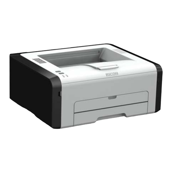
- Page 5 Slide 5 The OP-P1 has only a printer function. It doesn't have a full operation panel but has 2 keys and 2 LEDs. The top of the machine is covered by a plastic maintenance cover.
- Page 6 The 3-in-1 model has a larger operation panel than OP-P1, with more buttons and a 2-digit display. The top of the machine is covered by a platen cover and flatbed scanner unit, except for the M148, M166, and M191, which have an ADF instead of a platen cover.
- Page 7 OP-P1/MF1 Training Appearance – OP-MF1 (4-in-1 Model) OP-MF1afh (M135), OP-MF1afhn (M143) OP-MF1afhu (M141) OP-MF1af (M149, M167), OP-MF1afn (M150, M168) OP-MF1afw (M151, M169) OP-MF1af: Copier + Printer + Scanner + Fax, With ADF OP-MF1afh: OP-MF1af + handset OP-MF1afn: OP-MF1af + Ethernet ...
- Page 8 OP-P1/MF1 Training External Components – OP-P1 1. Job Reset key 8. Tray 1 2. Start key 9. Power switch 3. Power indicator 10. Power connector 4. Alert indicator 11. Rear cover 5. Output tray 12. USB port 6. Front cover 13.
- Page 9 OP-P1/MF1 Training External Components – OP-MF1 (no ADF) 1. Exposure glass 8. Power switch 2. Operation panel 9. Power connector 3. Exposure glass cover 10. Rear cover 4. Output tray 11. USB port (Scan to USB not available in China) 5.
- Page 10 OP-P1/MF1 Training External Components – OP-MF1 (with ADF and handset) 1. Exposure glass 10. Power switch 2. Operation panel 11. Auto Document Feeder 3. Front cover 12. ADF input tray 4. Output tray 13. ADF cover 5. Bypass tray 14. Rear cover 6.
- Page 11 OP-P1/MF1 Training Operation Panel – Printer Chinese Version 1. Job Reset key 3. Power indicator 2. Start key 4. Alert indicator Slide 11 See the User's Guide for detailed operation panel descriptions.
- Page 12 OP-P1/MF1 Training Operation Panel – Printer International Version 1. Job Reset key 3. Power indicator 2. Start key 4. Alert indicator Slide 12 See the User's Guide for detailed operation panel descriptions.
- Page 13 OP-P1/MF1 Training Operation Panel – 3 in 1 Chinese Version 1. Document Type key 6. Copy Number key 2. Density indicator 7. Stop/Cancel key 3. Density key 8. Start key 4. ID Copy key 9. Power indicator 5. Display LCD 10.
- Page 14 OP-P1/MF1 Training Operation Panel – 3 in 1 International Version 1. Document Type key 6. Copy Number key 2. Density indicator 7. Stop/Clear key 3. Density key 8. Start key 4. ID Copy key 9. Power indicator 5. Display LCD 10.
- Page 15 OP-P1/MF1 Training Operation Panel – 4 in 1 Chinese Version 1. Fax key 8. Start key (Fax tx/rx) 2. Copy key 9. Power indicator 3. Speed dial key 10. Display screen 4. ID card copy/On hook key 11. Alert indicator 5.
- Page 16 OP-P1/MF1 Training Operation Panel – 4 in 1 International Version 1. Fax key 8. Start key (Fax tx/rx) 2. Copy key 9. Scanner key 3. Speed dial key 10. Power indicator 4. ID card copy/On hook key 11. Display screen 5.
- Page 17 OP-P1/MF1 Training Market Positioning and Concepts Main Objective Maintain and expand MIF in the low end market Target Users Business personal and small office Can double as a small office printer/copier/fax Technical Enhancements (compared to some competitors/predecessors) ...
- Page 18 OP-P1/MF1 Training Yield Targets Toner yield (Starter AIO): About 1000 pages Toner yield (Replacement AIO, Supply): High yield: About 2600 pages Low yield: About 1500 pages (except for the China models [M133, M134, M135, M141, M142, M143, M144, M191]) »...
-
Page 19: Reliability Targets
OP-P1/MF1 Training Reliability Targets Average Print Volume OP-P1a: 400 prints/month OP-MF1a: 500 prints/month OP-P1a/OP-MF1a (China models): 800 prints per month MPBF OP-P1a: 26k prints OP-MF1a: 22k prints Expected product life All models: 5 years or 60,000 prints (whichever... -
Page 20: Service Training
OP-P1/MF1 Training Model OP-P1/MF1 Service Training 2. Specifications Slide 20 No additional notes... -
Page 21: General Specifications
OP-P1/MF1 Training General Specifications - 1 Print/Copy speed: Up to 22 ppm (A4/LT SEF) Warm up time: Less than 25 s at 23 C First print time: Less than 6 s from the start of paper feed until paper exits. - Page 22 OP-P1/MF1 Training General Specifications - 2 Maximum original & print size: A4, 8½" x 14" Paper size Standard Tray: A4, Letter, Half letter, B5 (ISO), A5, B6, A6, Executive, 16K, Legal Bypass Tray: Width 100 mm to 216 mm (3.5" to 8.5“), Length 148 mm to 356 mm (5.8"...
- Page 23 OP-P1/MF1 Training General Specifications - 3 Memory size: OP-P1a: 16 MB OP-MF1au: 16 MB OP-MF1afh, OP-MF1afhu: 32 MB No upgrades available Hard disk: None Not available as standard or as option Fax ...
- Page 24 OP-P1/MF1 Training Model OP-P1/MF1 Service Training 3. Installation Slide 24 No additional notes...
- Page 25 OP-P1/MF1 Training Overview Generally, the user installs this machine. However, in addition to your maintenance duties, you may also have to install the machine when you are in the field. The full installation procedure is in the Quick Installation Guide.
-
Page 26: Space Requirements
OP-P1/MF1 Training Space Requirements Printer model With platen cover With ADF Slide 26 No additional notes... -
Page 27: Install The Machine
OP-P1/MF1 Training Install the Machine The following are the main steps to installation. Refer to the Quick Installation Guide (QIG) for details. Unpack the machine. Take out the AIO (print cartridge), shake it 5 or 6 times, and reinstall it. - Page 28 OP-P1/MF1 Training Model OP-P1/MF1 Service Training 4. Machine Overview Slide 28 No additional notes...
-
Page 29: Component Layout
OP-P1/MF1 Training Component Layout 1. Exit Rollers 7. Transfer Roller 2. Straight Rollers 8. Registration Sensor 3. Exit Sensor 9. Paper 4. Hot Roller 10. Feed Roller 5. Pressure Roller 11. Manual Feed Tray 6. Drum 12. Connecting Roller Slide 29... -
Page 30: Electrical Component Layout
OP-P1/MF1 Training Electrical Component Layout – 1 Front Door Switch 8. Paper End Sensor Operation Panel Unit 9. Registration Sensor Main Board 10. By-pass Set Sensor Interlock Switch (Fusing Unit Cover) 11. Paper Feed Clutch Main Switch 12. Main Motor 13. - Page 31 OP-P1/MF1 Training Electrical Component Layout – 2 14 15 14. ID Chip 20. Thermostat 15. LD Board 21. Fusing Thermistor (End) 16. Thermistor 22. Fax Board (4-in-1 models) 17. Polygon Mirror Motor 23. Speaker (4-in-1 models) 18. Fusing Lamp 19. Fusing Thermistor (Center) Slide 31 16.
- Page 32 OP-P1/MF1 Training Electrical Component Layout – 3 24.Scanner Motor 25.ADF Motor 26.ADF Sensor 1 27.ADF Sensor 2 28.CIS 29.Operation Panel Unit Items 24 to 28: 3-in-1 and 4-in- 1 models only Items 25 to 27: Only in models with ADF...
- Page 33 OP-P1/MF1 Training Main Unit Drive The main motor (1) and a gear train (2) drive the feed roller (3) and transport roller (4), the drum (5, inside the AIO), the hot roller (6), the fusing exit roller (7), and the exit roller (8).
- Page 34 OP-P1/MF1 Training Control Structure – Printer model Panel Key/LED Front Door Swich (I / L) Thermistor Fusing Thermistor (Center) Main Motor Main Motor Paper Exit Sensor Fusing Thermistor (End) By-pass Set Sensor Registration Sensor Paper End Sensor Rear Cover Switch...
- Page 35 OP-P1/MF1 Training Control Structure – 3-in-1 model Scanner Motor Panel Key / LED Front Door Swich (I / L) Thermistor Fusing Thermistor (Center) Main Motor Polygon Mirror Motor Paper Exit Sensor Fusing Thermistor (End) By-pass Set Sensor Registration Sensor Paper End Sensor...
- Page 36 OP-P1/MF1 Training Control Structure – 4-in-1 model Scanner ADF Sensor 1 ADF Sensor 2 Motor Motor Operation Panel Front Door Switch (I / L) Thermistor Fusing Thermistor (Center) Main Motor Polygon Mirror Motor Paper Exit Sensor Fusing Thermistor (End) By-pass Set Sensor...
-
Page 37: Adf Paper Path
OP-P1/MF1 Training ADF Paper Path The solid red line shows the path that documents take through the ADF. Slide 37 No additional notes... - Page 38 OP-P1/MF1 Training Main Unit Paper Path The red line shows the path that paper takes through the machine. Slide 38 1. Paper Exit Sensor 2. Fusing Exit Roller 3. Exit Roller 4. Hot Roller 5. Pressure Roller 6. Drum 7.
-
Page 39: Loading Paper
OP-P1/MF1 Training Loading Paper Before loading paper, the paper size and paper type must be selected on the initial screen (System Settings) of the Smart Organizing Monitor. Also, in print mode, the user must select the correct size on the printer driver. - Page 40 OP-P1/MF1 Training Message and Error Displays The 4-in-1 models have a 2-line display that can show SC codes and messages. The display for the 3-in-1 models is limited to two digits. The printer model has no display.
-
Page 41: Service Training
OP-P1/MF1 Training Model OP-P1/MF1 Service Training 5. Maintenance (Maintenance, Service mode, Cleaning) Slide 41 No additional notes... -
Page 42: Maintenance Procedures
OP-P1/MF1 Training Maintenance Procedures This machine is designed for user maintenance; so, it does not have a periodic maintenance schedule. Refer to the maintenance information in the User Guide. Operating Instructions: User Guide Maintaining the Machine ... -
Page 43: Configuring The Machine
OP-P1/MF1 Training Configuring the Machine The 4-in-1 models can be configured/set-up from the control panel. User Guide Configuring the Machine Using the Control Panel All models can be configured/set-up using the Smart Organizing Monitor. User Guide Configuring the Machine Using the... -
Page 44: Using The Service Mode
OP-P1/MF1 Training Using the Service Mode The method for entering the service mode depends on the function item and the model. Refer to the table below. The Service Mode PC utility is accessed from within the Smart Organizing Monitor. - Page 45 OP-P1/MF1 Training Opening the Service Mode Image area "About" button To open the Service Mode: Step 1: Click "About". Step 2: Press Ctrl+Shift and double click the right mouse button in the image area of the Smart Organizing Monitor. (Orange outlined area above.)
-
Page 46: Updating Firmware
OP-P1/MF1 Training Updating Firmware - 1 Always update the firmware in READY mode. If you update firmware while copying or printing or in the energy saver modes, the update will fail. Make sure that the PC is set so that it does not enter standby mode or sleep mode automatically during the firmware update. - Page 47 OP-P1/MF1 Training Updating Firmware - 2 To begin the update, click the [User Tools] tab, and then click [Printer Configuration]. Click [Printer Firmware Update]. Follow the procedure in the service manual. The manual explains what the machine displays during the update and after the update has finished.
- Page 48 OP-P1/MF1 Training If Firmware Update Fails Engine firmware update: If the firmware update fails, SC871 appears (3-in-1 models show c7, and in the printer version, only the Alert LED lights). The main board must be replaced. Controller firmware update: If the firmware update fails, try again.
- Page 49 OP-P1/MF1 Training Cleaning This machine is designed for user maintenance; so, it does not have a periodic maintenance schedule. As a preventive maintenance measure, you may need to clean machine components during service calls. Go to the machine and practice the cleaning procedures.
-
Page 50: Print Counter
OP-P1/MF1 Training Print Counter Count-up is done at the time of image writing. So in this machine, count-up is done even when jam detection occurs after writing. This process differs from existing machines, where count-up is done after feeding out the printed paper. - Page 51 OP-P1/MF1 Training Model OP-P1/MF1 Service Training 6. Detailed Section Descriptions Slide 51 No additional notes...
- Page 52 OP-P1/MF1 Training Model OP-P1/MF1 Service Training Detailed Section Descriptions Scanning Slide 52 No additional notes...
-
Page 53: Adf - Overview
OP-P1/MF1 Training ADF - Overview The ADF can hold up to 15 originals for continuous scanning. Originals can also be scanned from the exposure glass one at a time (book mode). Slide 53 1. Original Feed Tray 2. Pick-up Roller 3. - Page 54 OP-P1/MF1 Training ADF – Operation (1) The originals are placed face-up. The original feed tray (1) can hold up to 15 originals. The pick-up roller (2) feeds each original into the ADF after the operator pushes [Start] on the operation panel.
- Page 55 OP-P1/MF1 Training ADF – Operation (2) The ADF roller (4) feeds the original into the ADF and sends it down. ADF sensor 2 (5) detects the leading and trailing edge of each original as passes and continues to feed past the feed roller (6).
- Page 56 OP-P1/MF1 Training ADF – Operation (3) The 2nd feed roller feeds the paper over the ADF scanning glass (7). The stationary CIS (8) below the ADF scanning glass scans the original as it passes overhead. The exit roller (9) feeds to original out of the ADF and onto the original output tray (10).
- Page 57 OP-P1/MF1 Training ADF – Operation (4) Original Feed Original Direction ADF Scanning Glass In ADF mode, the CIS stays below the ADF scanning glass during scanning. Slide 57 The CIS is shaded in yellow in this diagram.
- Page 58 OP-P1/MF1 Training Flatbed Scanner – Operation CIS Movement Original Direction ADF Scanning Glass To scan an original placed face down on the exposure glass, the CIS is moved from left to right by a timing belt. The timing belt does not move when scanning originals from the ADF.
-
Page 59: Adf Components
OP-P1/MF1 Training ADF Components The ADF (A) is mounted on top of the flatbed scanner (B). Slide 59 1. Operation Panel 2. ADF Motor 3. Original Set Sensor (ADF Sensor 1) 4. Original Feed Sensor (ADF Sensor 2) 5. CIS Unit 6. - Page 60 OP-P1/MF1 Training Flatbed Scanner Components The CIS and flatbed scanner motor are the only two electrical components in the flatbed scanner. Slide 60 1. CIS 2. CIS Cradle 3. Timing Belt 4. Scanner Motor...
- Page 61 OP-P1/MF1 Training Flatbed Hinge Mechanism - 1 1. Flatbed Scanner Unit Base 2. Support Arm 3. Guides 4. Spring Slide 61 No additional notes...
- Page 62 OP-P1/MF1 Training Flatbed Hinge Mechanism - 2 The hinge is mounted on the top of the left cover and connected to the bottom of the flatbed unit. The hinge locks and holds when the top of the machine is raised.
- Page 63 OP-P1/MF1 Training Flatbed Hinge Mechanism - 3 There is only one hinge, on the left. The top of the hinge is connected to the base of the flatbed scanner [1]. The end (convex part) [3] of the support arm [2] is joined to the guide [4].
-
Page 64: Replacement Of Parts
OP-P1/MF1 Training Replacement of Parts The only serviceable part in the ADF is the original tray cover. If other part malfunctions occur, replace the whole ADF. Slide 64 No additional notes... -
Page 65: Service Training
OP-P1/MF1 Training Model OP-P1/MF1 Service Training Detailed Section Descriptions Laser Unit Slide 65 No additional notes... - Page 66 OP-P1/MF1 Training Top View, Cover On 1. Top Cover 2. Laser Decal 3. LD Board Slide 66 No additional notes...
- Page 67 OP-P1/MF1 Training Top View, Cover Off Laser Diode Collimating Lens Aperture Cylindrical Lens Polygon Mirror Laser Synchronization Detector F-theta Lens 1st Mirror Shield Glass 10. Thermistor Slide 67 The thermistor [10] monitors the temperature in the machine, and the print job stops when it is more than 52 degrees Celsius to let the machine cool down.
- Page 68 OP-P1/MF1 Training Laser Unit Operation (1) The laser diode [1] emits a single laser beam. A collimating lens [2] shapes the laser beam, which then passes through the aperture [3] and cylindrical lens [4]. The aperture and cylindrical lens focus the beam and aim it at the polygon mirror.
- Page 69 OP-P1/MF1 Training Laser Unit Operation (2) The mirror rotates clockwise to the angle of reflection of the beam. There are four steps to scanning a single line onto the drum: Laser synchronization done by the laser synchronization detector [6] ...
- Page 70 OP-P1/MF1 Training Laser Unit Operation (3) After the laser beam is reflected from the polygonal mirror, it passes through the F-theta lens [7]. The first mirror [8] and shield glass [9] above the slit on the bottom of the laser unit deflect the laser beams from the F- theta lens downward onto the photoconductive surface of the drum.
- Page 71 OP-P1/MF1 Training Laser Unit – Cross-section View The polygon mirror [1] reflects the laser beam through the F-theta lens [2]. The first mirrors [3] deflect the beam through the shield glass [4] on the front bottom edge of the laser unit and onto the photoconductor surface of the drum below the laser unit.
-
Page 72: Safety Switches
OP-P1/MF1 Training Safety Switches Safety switches are installed on the front and the rear. They are turned On/Off when each cover (front or rear) are opened or closed. Front door switch: Turned on and off when the front cover is opened or closed. -
Page 73: Laser Unit Replacement
OP-P1/MF1 Training Laser Unit Replacement After replacing the laser unit, print the Test Page and check the position of the image area on the page, as explained in the replacement procedure in the service manual. There are no SP adjustments. - Page 74 OP-P1/MF1 Training Model OP-P1/MF1 Service Training Detailed Section Descriptions Image Creation Slide 74 No additional notes...
- Page 75 OP-P1/MF1 Training Introduction The print cartridge is called the AIO (all-in-one) throughout this course. All models in the series use the same AIO. There are no serviceable parts inside the AIO. Disassembly of an AIO is never required.
- Page 76 OP-P1/MF1 Training AIO (All-in-one) Unit Waste Toner Tank Development Roller Toner Hopper ID Chip Agitator Agitator Feeler Toner Supply Roller Transfer Roller Drum 10. Charge Roller 11. Cleaning Blade Slide 76 The print cartridge is called the AIO (all-in-one) throughout this course.
- Page 77 OP-P1/MF1 Training AIO Operation (1) The following steps are done for each sheet of paper: The charge roller [1] applies a charge to the photoconductive surface of the drum [2]. A developer/toner mixture from the toner supply unit [4] is picked up by the toner supply roller [5] and applied to the development roller [6].
- Page 78 OP-P1/MF1 Training AIO Operation (2) When the paper [7] passes between the drum [2] and the transfer roller [8], the charge on the transfer roller pulls the toner off the drum onto the paper to form the image. The cleaning blade [9] removes unused toner from the surface of the drum.
- Page 79 OP-P1/MF1 Training AIO Contact Points with Main Frame 1. AIO Unit 2. AIO Contact Terminal 3. AIO Contact Spring 4. Transfer Roller 5. Transfer Roller Pressure Spring 6. Base Leaf Spring 7. Transfer Roller Contact Spring 8. Base Plate 9. Base Plate Lock Pawl...
-
Page 80: Toner End Detection
OP-P1/MF1 Training Toner End Detection Printer models and 3-in-1 models, except for Europe and N. America models (M145, M146, M147, M148): There is no toner end detection mechanism. The operator replaces or refills the AIO when printouts become faint or blurred. - Page 81 OP-P1/MF1 Training Toner End Option (1) When the Toner End Option is set to ‘Stop Printing’: The toner near end and toner end alert functions are enabled. The toner near end alert will appear when toner supply runs low, and then about 50 pages can be printed until toner end.
- Page 82 OP-P1/MF1 Training Toner End Option (2) When the Toner End Option is set to ‘Continue Printing’: The toner level in the AIO is not monitored. The machine will continue printing even after toner runs out because the toner near end and toner end alerts will not appear.
- Page 83 OP-P1/MF1 Training Toner End Option (3) When Toner End Option is on ("Stop Printing" selected), the toner near end and toner end alerts will appear in the Error history box of the Service Mode Screen of Smart Organizing Monitor.
- Page 84 OP-P1/MF1 Training After Toner End The operator can force print from the AIO even after the toner end message appears by switching off the Toner End Option: [User Tools] > System Settings > Toner End Option > Continue Printing ...
- Page 85 OP-P1/MF1 Training Toner Consumption Toner Remains Rotation Time Toner Remains Progress Bar The rate of toner consumption depends on the type of documents that are printed. In the illustration above: Line A shows toner consumption when documents consistently contain a large number of images that require area filling (photos, bar charts, grayscale).
- Page 86 OP-P1/MF1 Training AIO Replacement - 1 When toner runs out, the AIO can be refilled by the service technician or the AIO can be replaced by the operator. Refilling requires removal of two caps: the square cap to dump the toner and the round cap for refilling.
- Page 87 OP-P1/MF1 Training AIO Replacement - 2 The ID chip on the AIO tells the machine that an AIO is installed. It is also used to detect when a new AIO is installed in the machine. If a new AIO is detected, the toner counter is reset automatically.
-
Page 88: Refilling The Aio
OP-P1/MF1 Training Refilling the AIO (All models except the Europe and N. America models) The AIO is easy to refill. (Just remove caps to refill the toner and remove waste toner. There are no screws to remove.) Drum life is the limiting factor. The AIO can be refilled 2 or 3 times (depends on use). - Page 89 OP-P1/MF1 Training Replacing the High-voltage Power Pack (HVPP) There are four AIO springs but only three terminal nodes [A] (the black one doesn’t have a terminal node.) Be sure to re-attach the black spring at the place marked with a red circle, and then the other springs with the terminal nodes in the other holes.
-
Page 90: Service Training
OP-P1/MF1 Training Model OP-P1/MF1 Service Training Detailed Section Descriptions Paper Feed Slide 90 No additional notes... - Page 91 OP-P1/MF1 Training Mechanism - 1 The main motor drives the feed roller (10) to feed paper from the tray. Only one sheet passes the feed roller and friction pad. The registration sensor (8) detects the leading edge of the paper.
- Page 92 OP-P1/MF1 Training Mechanism - 2 The paper passes between the drum (6) and the transfer roller (7). The transfer roller pulls the toner image from the drum onto the paper. The toner image is fused onto the paper when it passes between the hot roller (4) and pressure roller (5).
- Page 93 OP-P1/MF1 Training Mechanism - 3 Finally, the paper passes through the exit roller (3) and is stacked face-down on the output tray. When there is no paper in the tray, a feeler falls through a cutout in the bottom plate, triggering the paper end sensor.
- Page 94 OP-P1/MF1 Training Drive The main motor (1) and a gear train (2) drive the feed roller (3) and transport roller (4), the drum (5, inside the AIO), the hot roller (6), the fusing exit roller (7), and the exit roller (8).
- Page 95 OP-P1/MF1 Training Model OP-P1/MF1 Service Training Detailed Section Descriptions Image Transfer Slide 95 No additional notes...
-
Page 96: Image Transfer
OP-P1/MF1 Training Image Transfer The positively Drum (Negatively charged transfer charged roller attracts the toner image) negatively charged toner from the drum to the paper. Paper Transfer roller (Strong positive charge) Slide 96 No additional notes... -
Page 97: Replacing The Transfer Roller
OP-P1/MF1 Training Replacing the Transfer Roller Note the correct way to install a new roller, as shown on the left: The black collar must be on the right end of the roller [A]. The white collar must be on the left end of the roller [B]. - Page 98 OP-P1/MF1 Training Model OP-P1/MF1 Service Training Detailed Section Descriptions Fusing Slide 98 No additional notes...
-
Page 99: Cross-Section View
OP-P1/MF1 Training Cross-section View 1. Hot Roller 2. Thermostat (Center) 3. Thermistor (Center, Edge) 4. Fusing Lamp 5. Entrance Guide 6. Pressure Roller 7. Pressure Arm 8. Fusing Exit Roller 9. Separation Pawls (x3) 10. Paper Exit Sensor 11. Paper Exit Roller... - Page 100 OP-P1/MF1 Training Fusing Unit Specifications Fusing method: Hot roller Fusing lamp: Halogen lamp, 700W Hot roller diameter: 25 mm Hot roller surface: 0.7mm thick Pressure roller diameter: 25 mm Fusing unit drive: Main motor ...
-
Page 101: Main Components
OP-P1/MF1 Training Main Components The hot roller (1) contains the fusing lamp (2) (a halogen lamp). The hot roller and pressure roller (3) are pressed together by two strong springs [A] attached to arms [B] at the left and right ends of the fusing unit. - Page 102 OP-P1/MF1 Training Fusing Unit Ground Plates Ground plates are attached to the fusing unit at two points: One point on the hot roller at [1] and at one point on the pressure roller [2]. Slide 102 No additional notes...
-
Page 103: Temperature Control
OP-P1/MF1 Training Temperature Control (1) The thermistors (center and right end) [3] touch the surface of the hot roller [1]. They measure the temperature of the hot roller surface every 50 The center thermistor detects temperature where paper passes... - Page 104 OP-P1/MF1 Training Temperature Control (2) Reload Temp. Idling Start Temp. Temp. Reading (Thermistor) Time In Energy Save Mode 2 at "A" (while the machine is idle), the fusing lamp inside the hot roller switches on. At "B", the hot roller and pressure roller start to idle so that the heat from the fusing lamp is transferred and distributed evenly over the surfaces of these rollers.
- Page 105 OP-P1/MF1 Training Temperature Control (3) Reload Temp. Idling Start Temp. Temp. Reading (Thermistor) Time Fusing temperature control keeps the hot roller temperature constant during a print job at "D". When the job is finished, the machine returns to standby mode "C" and is ready to start the next job as soon as it is received.
-
Page 106: Energy Save Modes
OP-P1/MF1 Training Energy Save Modes Energy Save Mode 1 If enabled (the default is ‘off’), the machine enters this mode if the machine remains idle for more than 30 sec. » The idle time setting (30 sec.) is not adjustable. -
Page 107: Paper Exit
OP-P1/MF1 Training Paper Exit The paper exits the machine at the front after it passes through the fusing unit. The exit rollers, driven by the main motor, feed the paper out of the fusing unit and onto the output tray. - Page 108 OP-P1/MF1 Training Model OP-P1/MF1 Service Training 7. Replacement and Adjustment Slide 108 These are general comments about replacement and adjustment. Details for each section were discussed in the relevant part of the course.
-
Page 109: Before You Start
OP-P1/MF1 Training Before You Start Safety Precautions It is important to observe the all safety precautions during maintenance work. Refer to the safety precautions in the field service manual. » FSM Safety, Symbols, Trademarks » FSM Replacement and Adjustment Before You Begin ... -
Page 110: Removing And Replacing Parts
OP-P1/MF1 Training Removing and Replacing Parts Disassembly The procedures are not all the same for each model. The manual contains procedures for all models. Make sure you are looking at the correct procedure before you start. Observe all notes and cautions. -
Page 111: Replacing Boards
OP-P1/MF1 Training Replacing Boards Before board replacement, enter the SP mode to output reports (Service Date List, Fax Dial List, and Fax Speed Dial List). Refer to these reports when making settings after replacement. After replacing the Main Board, use SOM to make settings as explained in the service manual. - Page 112 OP-P1/MF1 Training Model OP-P1/MF1 Service Training 8. Troubleshooting Slide 112 This section explains the basic points about machine troubleshooting. Refer to the service manual for details on how to recover from the error codes.
- Page 113 OP-P1/MF1 Training What Happens when an Error Occurs? - 1 When an error occurs, the alert indicator on the operation panel lights and the machine stops. A buzzer will sound an alert on the 4-in-1 models. Press any key on the operation panel to turn the buzzer off.
- Page 114 OP-P1/MF1 Training What Happens when an Error Occurs? - 2 Printer model 3-in-1 4-in-1 The printer models have no panel display. When an error occurs, only the alert lamp lights [1]. The 3-in-1 models have a 2-segment display [1]. A letter-number code is used.
- Page 115 OP-P1/MF1 Training What Happens when an Error Occurs? - 3 Error History Error codes can be viewed in the Error History box of the Service Mode screen in Smart Organizing Monitor. After a fatal fusing error you must execute [Fuser SC Reset] to recover machine operation.
- Page 116 OP-P1/MF1 Training Model OP-P1/MF1 Service Training 9. Technology for Environmental Conservation Slide 116 This section explains the technology used in this machine for environmental conservation, and the default settings of related functions.
- Page 117 OP-P1/MF1 Training Technology for Environmental Conservation **: New or modified function *: Has this function Blank: Does not have this function Environmental Technology/Feature Description OP-P1/MF1 1. QSU - Reduction of warm-up time (Energy saving) 2. Hybrid QSU - Reduction of CO emissions 3.
- Page 118 OP-P1/MF1 Training Brief Descriptions of the Technologies 1. QSU (Quick Start-up) This technology reduces both the amount of energy consumed while in Standby mode (the Ready condition) is reduced, as well as the time it takes for the machine to warm up to the Ready condition.
- Page 119 OP-P1/MF1 Training Brief Descriptions of the Technologies 3. IH QSU This technology incorporates IH (Inductance Heating) technology into conventional QSU technology, which allows the benefits of reduced energy consumption and reduced warm-up time to be extended to color machines.
- Page 120 OP-P1/MF1 Training Brief Descriptions of the Technologies 5. High-speed duplex output 1) Enables high-speed duplex printing through the utilization of the Duplex Interleaf and high- speed Inverter Transport features. 2) Enables quick printing of duplex jobs through the use of Duplex Scanning.
- Page 121 Brief Descriptions of the Technologies 7. PxP (polymerized) toner "PxP toner" is a fine-particle, polyester resin based toner, manufactured using a Ricoh-original polymerization method instead of the conventional pulverization method. This allows the toner to fuse at a lower...
- Page 122 1) Products sold in the EU conform to the RoHS Directive. 2) Products sold in China conform to China's version of the RoHS Directive. 3) In addition, Ricoh imposes strict internal standards for limiting the presence of harmful substances. Slide 122...
- Page 123 OP-P1/MF1 Training Brief Descriptions of the Technologies 10. Environmentally-friendly toner bottle A changeover from PS/PP/HDP to PET plastics allows approximately 40 percent by weight of the toner bottle to be recycled, and also reduces CO emissions that occur during the toner bottle manufacturing process.
- Page 124 OP-P1/MF1 Training Energy Saving Overview Power Operating Stand-by Mode Warm-up Energy Saving Energy Saver Mode 1 Energy Saver Mode 2 Energy Saver Mode 1 Timer 30 sec. Cold Start Time Energy Saver Mode 2 timer Setting range: See below After 240min.
- Page 125 OP-P1/MF1 Training End of Course Slide 125 No additional notes...