York YK Series Installation Manual
Chillers (style h) field reassembly for form 3, 7, 9, and 10 shipment
Hide thumbs
Also See for YK Series:
- Operation manuals (220 pages) ,
- Operation and maintenance (38 pages)
Table of Contents
Advertisement
Quick Links
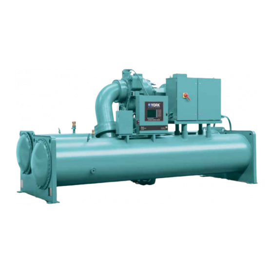
Model YK Chillers (Style H) Field
Reassembly for Form 3, 7, 9, and 10
Shipment
R-134a and R-513A (Cooling Only) with Graphic Control
Center for Electromechanical Starter, Solid State Starter,
and Variable Speed Drive
Installation Guide
Issue Date: 2021-01-15
Form Number: 160.76-N3 (121)
Supersedes: 160.76-N3 (619)
Advertisement
Table of Contents

Related Manuals for York YK Series


Summary of Contents for York YK Series
- Page 1 Model YK Chillers (Style H) Field Reassembly for Form 3, 7, 9, and 10 Shipment R-134a and R-513A (Cooling Only) with Graphic Control Center for Electromechanical Starter, Solid State Starter, and Variable Speed Drive Installation Guide Form Number: 160.76-N3 (121) Issue Date: 2021-01-15 Supersedes: 160.76-N3 (619)
- Page 2 Model YK Chillers (Style H) Field Reassembly for Form 3, 7, 9, and 10 Shipment...
-
Page 3: Table Of Contents
Contents General safety guidelines..........................5 C o n t e n t s Safety symbols............................. 5 Changeability of this document......................6 Associated literature........................... 6 Nomenclature............................7 Shipping and reassembly..........................8 Forms of shipment..........................8 Form 3 – Driveline separate from shells....................8 Form 7 –... - Page 4 Model YK Chillers (Style H) Field Reassembly for Form 3, 7, 9, and 10 Shipment...
-
Page 5: General Safety Guidelines
General safety guidelines Important: Read before proceeding. This equipment is a relatively complicated apparatus. During rigging, installation, operation, maintenance, or service, individuals may be exposed to certain components or conditions including, but not limited to: heavy objects, refrigerants, materials under pressure, rotating components, and both high and low voltage. -
Page 6: Changeability Of This Document
WARNING External wiring, unless specified as an optional connection in the manufacturer’s product line, is not to be connected inside the control cabinet. Devices such as relays, switches, transducers and controls and any external wiring must not be installed inside the micro panel. All wiring must be in accordance with Johnson Controls’... -
Page 7: Nomenclature
Manual description Form number Wiring Diagrams - Field Connections - Remote Mounted MVVSD 160.76-PW3 Wiring Diagrams - Field Control Modifications 160.76-PW4 Wiring Diagrams - OptiView Control Center and EMS 160.76-PW5 Wiring Diagrams - OptiView Control Center and SSS, LVVSD 160.76-PW6 Wiring Diagrams - Field Connections - LVVSD 160.76-PW7 Unit Operation and Maintenance... -
Page 8: Shipping And Reassembly
Shipping and reassembly This instruction explains the procedure to be used for reassembling the Model YK Chiller shipped disassembled (Shipping Form 3, 7, 9, and 10). Note: Chillers must be field reassembled under the supervision of a Johnson Controls representative. For instructions on installing the unit, refer to the Unit Installation Instructions (Form 160.76-N1). -
Page 9: Form 7 - Split Shells
The shipment may include miscellaneous packaging of the control center, oil eductor filter, tubing, water temperature controls, wiring, oil, isolators, solid state starter or variable speed drive (options). The refrigerant charge is shipped in appropriate cylinders. For P and Q compressors, the control panel is removed for shipment. -
Page 10: Inspection - Damage - Shortage
Inspection – damage – shortage The unit shipment must be checked on arrival to see that all major pieces, boxes, and crates are received. Each unit must be checked on the trailer or rail car when received, before unloading, for any visible signs of damage. -
Page 11: Long-Term Storage
Long-term storage About this task: In order to protect the waterbox of pressure vessels from rusting, the tube side (water side) has been purged and charged with nitrogen to a positive pressure of 5 psig to 7 psig. Do not break the seal or remove closures until ready for setup. Use the following procedure to relieve pressure. - Page 12 Figure 3: Long term storage - tube side Item Description Tag warning Dennison 8E Gauge press 2 dia. 0-30 Tag GlvSt wire speed Bush pipe 3/4 - 14 NPTE X Valve, transducer 1/4 NPTE X Flange cover Gasket Victaulic coupling Sealing cap Model YK Chillers (Style H) Field Reassembly for Form 3, 7, 9, and 10 Shipment...
-
Page 13: Shipment Form 2/3/7/9
Shipment Form 2/3/7/9 All openings on the compressor, shells including evaporator and condenser, and oil reservoir are closed and charged with nitrogen (2 psig to 3 psig). WARNING To remove the closures, sealing caps, or sealing plug under pressure is extremely dangerous, and may cause severe injury or death to the operator or people on-site. -
Page 14: Form 3 And Form 7 Shipment
Form 3 and Form 7 shipment Assemble vibration isolators to unit. Refer to the Unit Installation Instructions (Form 160.76-N1). Level shells in both directions. Check the longitudinal alignment of the shell by placing a level on the top of the shell, next to the discharge connection. Check the transverse alignment by placing a level on the tops of both end sheets. -
Page 15: Form 9 And Form 10 Reassembly
Figure 4: Rigging – compressor/motor assembly Note: Rig the driveline into place on the chiller, supporting the compressor with two lifting lugs and the motor with either, one, two, or four legs depending on motor design. Form 9 and Form 10 reassembly Assemble vibration isolators to unit. - Page 16 Note: Relief valves must be plugged or capped. Refer to Operations and Maintenance (Form 160.76-O1). Form 9 - Remove nitrogen and charge unit with refrigerant. Refer to Operations and Maintenance (Form 160.76-O1). 10. All Units: Complete installation and finally level the unit. Refer to Installation Manual (Form 160.76-N1).
-
Page 17: Q3-Q8 Compressors (With Falling Film)
Q3-Q8 compressors (with falling film) Figure 6: Form 3 shipment (Q3-Q8 compressors with falling film) Note: * Ring Gaskets NOT used for elastomer-lined flange faces at the isolation valve. Model YK Chillers (Style H) Field Reassembly for Form 3, 7, 9, and 10 Shipment... - Page 18 Figure 7: Form 7 shipment (Q3-Q8 compressors with falling film) Note: * Ring Gaskets NOT used for elastomer-lined flange faces at the isolation valve. Model YK Chillers (Style H) Field Reassembly for Form 3, 7, 9, and 10 Shipment...
-
Page 19: Q3-Q8 Compressors
Q3-Q8 compressors Figure 8: System piping (Q3-Q8 compressors) Model YK Chillers (Style H) Field Reassembly for Form 3, 7, 9, and 10 Shipment... -
Page 20: P8-P9, H9 Compressors (With Falling Film)
P8-P9, H9 compressors (with falling film) Figure 9: Form 3 shipment (P8-P9 and H9 compressors with falling film) Note: * Ring Gaskets NOT used for elastomer-lined flange faces at the isolation valve. Model YK Chillers (Style H) Field Reassembly for Form 3, 7, 9, and 10 Shipment... - Page 21 Figure 10: Form 7 shipment (P8-P9 and H9 compressors with falling film) Note: * Ring Gaskets NOT used for elastomer-lined flange faces at the isolation valve. Model YK Chillers (Style H) Field Reassembly for Form 3, 7, 9, and 10 Shipment...
-
Page 22: P8-P9 And H9 Compressors
P8-P9 and H9 compressors Figure 11: System piping (P8-P9 and H9 compressors) Model YK Chillers (Style H) Field Reassembly for Form 3, 7, 9, and 10 Shipment... -
Page 23: K Compressors
K compressors Figure 12: Form 3 shipment (K compressors) Note: * Ring Gaskets NOT used for elastomer-lined flange faces at the isolation valve. Model YK Chillers (Style H) Field Reassembly for Form 3, 7, 9, and 10 Shipment... - Page 24 Figure 13: Form 7 shipment (K compressors) Note: * Ring Gaskets NOT used for elastomer-lined flange faces at the isolation valve. Model YK Chillers (Style H) Field Reassembly for Form 3, 7, 9, and 10 Shipment...
- Page 25 Figure 14: System piping (K compressors) Model YK Chillers (Style H) Field Reassembly for Form 3, 7, 9, and 10 Shipment...
-
Page 26: Weights
Weights Table 1: Compressor weights Compressor only D Flange only Total Compressor model 1835 2272 1030 1835 2272 1030 2162 2616 1186 2162 2616 1186 2075 2524 1145 1974 2418 1097 2776 1259 3281 1488 2897 1314 3408 1546 4271 1937 4989 2262... - Page 27 Table 2: WEG - Low voltage premium efficiency motor weights 60 Hz 50 Hz Code Weight (lb) Weight (kg) Code Weight (lb) Weight (kg) 1367 1367 1610 1610 1653 1653 1764 1764 2227 1012 2227 1012 2293 1042 2293 1042 2293 1042 2293...
- Page 28 Table 3: 60 Hz - Medium voltage (2300, 3300, 4000, 4160) motor weights Code Weight (lb) Weight (kg) 6950 3159 6950 3159 6950 3159 7420 3373 7420 3373 7420 3373 7714 3506 7714 3506 7714 3506 7714 3506 7714 3506 7714 3506 10531...
- Page 29 Table 5: 60 Hz - Low voltage variable speed drives Rigging weight Shipping weight Model number VSD270RKFT-40 1,038 1,338 VSD351RKFT-46 1,038 1,338 VSD385RKFT-40 1,038 1,338 VSD424RKFT-58 1,038 1,338 VSD503RKFT-46 1,226 1,560 VSD608RKFT-40 1,582 1,902 VSD608RKFT-42 1,226 1,902 VSD608RKFT-58 1,226 1,560 VSD790RKFT-46 1,582 1,902...
- Page 30 Table 6: 50 Hz - Low voltage variable speed drives Rigging weight Shipping weight Model number VSD292RKFT-50 1,058 1,358 VSD292RKFT-68 1,058 1,358 VSD419RKFT-50 1,246 1,546 VSD419RKFT-68 1,246 1,546 VSD658RKFT-43 1,602 1,952 VSD658RKFT-50 1,602 1,952 VSD704RKFT-68 1,602 1,952 VSD868RKFT-50 1,730 1,900 VSD914RKFT-43 1,730 1,900...
- Page 31 Note: The weights provided in the following table are intended to be a general reference only. The weights are based on the heaviest anticipated unit combinations as of December 2020. There are numerous factors that can impact these values based on the chiller options selected at the time of the final unit rating.
- Page 32 The evaporator marine waterbox weights are to be added to the standard unit weights shown in Table 7. Table 8: Approximate evaporator marine waterbox weights, lb (kg) Unit Shipping weight Operating weight increase, lb (kg) increase, lb (kg) evaporator Compressor code 1-pass 2-pass...
- Page 33 The condenser marine waterbox weights are to be added to the standard unit weights shown in Table 7. Table 9: Approximate condenser marine waterbox weights, lb (kg) Unit Shipping weight Operating weight increase, lb (kg) increase, lb (kg) condenser Compressor code 1-pass 2-pass...
-
Page 34: Unit Conversion
To convert a temperature range (i.e., a range of 10°F) from Fahrenheit to Celsius, multiply by 5/9 or 0.5556. Example: 10.0°F range x 0.5556 = 5.6°C range © 2021 Johnson Controls. 5000 Renaissance Drive, New Freedom, York, PA 17349, USA. Subject to change without notice. All rights reserved.