Table of Contents
Advertisement
Quick Links
Advertisement
Chapters
Table of Contents

Related Manuals for York YCAL0012EC


Summary of Contents for York YCAL0012EC
- Page 1 AIR-COOLED LIQUID CHILLERS HERMETIC SCROLL Supersedes 150.66-NM2 (608) Form 150.66-NM2 (920) INSTALLATION, OPERATION, MAINTENANCE 035-21552-000 YCAL0012EC–YCAL0032EC AIR-COOLED SCROLL CHILLERS STYLE D WITH IPU II and I/O BOARDS (60 Hz) 9 1/2 TON TO 28 TON R-410A Issue Date: September 25, 2020...
- Page 2 FORM 150.66-NM2 ISSUE DATE: 09/25/2020 IMPORTANT! READ BEFORE PROCEEDING! GENERAL SAFETY GUIDELINES This equipment is a relatively complicated apparatus. which it is situated, as well as severe personal injury or During rigging, installation, operation, maintenance, death to themselves and people at the site. or service, individuals may be exposed to certain com- This document is intended for use by owner-authorized ponents or conditions including, but not limited to:...
- Page 3 Planned Service Agreement that leverages real time and generalized conditions. In lieu of the tradition- and historical data, delivering performance reporting, al maintenance program, a Johnson Controls YORK corrective actions required and data enabled guidance Conditioned Based Maintenance (CBM) program can for optimal operation and lifecycle assurance.
-
Page 4: Table Of Contents
FORM 150.66-NM2 ISSUE DATE: 09/25/2020 TABLE OF CONTENTS SECTION 1 - GENERAL CHILLER INFORMATION AND SAFETY ..........13 INTRODUCTION ............................13 WARRANTY ...............................13 SAFETY ..............................13 Standards for Safety ...........................13 RESPONSIBILITY FOR SAFETY ......................14 ABOUT THIS MANUAL ..........................14 MISUSE OF EQUIPMENT .........................14 Suitability for Application ........................14 Structural Support ..........................14 Mechanical Strength ..........................14 General Access ............................14... - Page 5 FORM 150.66-NM2 ISSUE DATE: 09/25/2020 TABLE OF CONTENTS (cont’d) MOVING THE CHILLER ..........................31 Lifting Weights .............................31 Unit Rigging ............................32 SECTION 4 - INSTALLATION ......................33 INSTALLATION CHECKLIST ........................33 HANDLING ..............................33 INSPECTION ..............................33 LOCATION AND CLEARANCES ......................33 Foundation ............................34 Ground Level Locations ........................34 Rooftop Locations ..........................34 Noise Sensitive Locations ........................34 SPRING ISOLATORS (OPTIONAL) ......................34...
- Page 6 FORM 150.66-NM2 ISSUE DATE: 09/25/2020 TABLE OF CONTENTS (cont’d) Water System ............................40 Flow Switch ............................40 Temperature Sensor(s) ........................40 EQUIPMENT STARTUP CHECKLIST .....................41 Checking the System Prior To Initial Start (No Power) ..............41 Compressor Heaters (Power ON – 24 Hours Prior To Start) ............41 Panel Checks (Power ON –...
- Page 7 FORM 150.66-NM2 ISSUE DATE: 09/25/2020 TABLE OF CONTENTS (cont’d) Unit Warning ............................105 Status Key Messages ........................106 Quick Reference List .........................106 DISPLAY/PRINT KEYS ...........................107 Oper Data key ............................107 Oper Data Quick Reference List .......................110 Print Key ............................. 111 Operating Data Printout ........................111 History Printout ..........................112 History Displays ..........................112 Software Version ..........................114...
- Page 8 FORM 150.66-NM2 ISSUE DATE: 09/25/2020 TABLE OF CONTENTS (cont’d) CONDENSER FAN CONTROL .......................131 LOW AMBIENT FAN CONTROL OPTION YCAL 0012 - 0021 UNITS ..........133 General ...............................133 Potentiometer Configuration ......................133 Wiring ..............................134 PROGRAMMING YCAL0012 - 0021 ......................135 LOW AMBIENT FAN CONTROL OPTION YCAL0025-0032 UNITS............136 CONFIGURATION (JUMPERS AND POTENTIOMETERS) ..............137 Wiring ..............................137 PROGRAMMING - YCAL 0025 - 0032 ....................138...
- Page 9 FORM 150.66-NM2 ISSUE DATE: 09/25/2020 TABLE OF CONTENTS (cont’d) ON-BOARD BATTERY BACK-UP ......................155 PLATE AND FRAME HEAT EXCHANGER (EVAPORATOR) HEATER ..........155 OVERALL UNIT INSPECTION .......................156 ISN CONTROL ............................157 Received Data (Control Data) ......................157 Transmitted Data ..........................157 ISN Operational and Fault Codes .....................159 BACNET AND MODBUS DATA COMMUNICATION ................160 SERIAL COMMUNICATION ANALOG VALUE DATA ................162 SERIAL COMMUNICATION BINARY VALUE DATA ................162...
- Page 10 FORM 150.66-NM2 ISSUE DATE: 09/25/2020 LIST OF FIGURES FIG. 1 – UNIT COMPONENTS ........................23 FIG. 2 – CONTROL/POWER PANEL COMPONENTS ................24 FIG. 3 – REFRIGERANT FLOW DIAGRAM ....................30 FIG. 4 – UNIT RIGGING/LIFTING ......................32 FIG. 5 – SINGLE-POINT SUPPLY CONNECTION – TERMINAL BLOCK, NON-FUSED DISCONNECT SWITCH OR CIRCUIT BREAKER (0012 - 0032) ..........37 FIG.
- Page 11 FORM 150.66-NM2 ISSUE DATE: 09/25/2020 LIST OF TABLES TABLE 1 – SETPOINTS ENTRY LIST .....................42 TABLE 2 – TEMPERATURES AND FLOWS ...................45 TABLE 3 – VOLTAGE LIMITATIONS .......................45 TABLE 4 – ETHYLENE GLYCOL CORRECTION FACTORS ..............46 TABLE 5 – TEMPERATURES AND FLOWS (SI) ..................47 TABLE 6 –...
- Page 12 FORM 150.66-NM2 ISSUE DATE: 09/25/2020 THIS PAGE INTENTIONALLY LEFT BLANK JOHNSON CONTROLS...
-
Page 13: Section 1 - General Chiller Information And Safety
COMMISSIONING). solutions and is not suitable for purposes other than those specified in this manual. • Only genuine YORK approved spare parts, oils, coolants, and refrigerants must be used. This manual contains all the information required for correct installation and commissioning of the unit, •... -
Page 14: Responsibility For Safety
This manual and any other document supplied with the unit are the property of YORK which reserves • Personal safety, safety of other personnel, and all rights. They may not be reproduced, in whole or the machinery. -
Page 15: Pressure Systems
FORM 150.66-NM2 SECTION 1 - GENERAl ChIllER INFORMATION AND SAFETy ISSUE DATE: 09/25/2020 Pressure Systems The unit contains refrigerant vapor and liquid under Frame rails, brakes, and other components may also pressure, release of which can be a danger and cause have sharp edges. - Page 16 FORM 150.66-NM2 ISSUE DATE: 09/25/2020 THIS PAGE INTENTIONALLY LEFT BLANK JOHNSON CONTROLS...
-
Page 17: Section 2 - Product Description
ISSUE DATE: 09/25/2020 SECTION 2 - PRODUCT DESCRIPTION 50091 INTRODUCTION Testing Services (ETL) and rated in accordance with YORK Millennium Air-Cooled Scroll Chillers provide ® ARI Standard 550/590-2003. chilled water for all air conditioning applications using central station air handling or terminal units. They are... -
Page 18: Condenser
• Suction pressure cutout setting • Chilled liquid temperatures • Each system suction pressure • Ambient temperature • Discharge pressure (optional) • System pressures (each circuit) • Liquid Temperature Reset via a YORK ISN DDC • Operating hours and starts (each compressor) JOHNSON CONTROLS... -
Page 19: Power Panel
FORM 150.66-NM2 SECTION 2 - PRODUCT DESCRIPTION ISSUE DATE: 09/25/2020 or Building Automation System (by others) via: Provisions are included for: pumpdown at shutdown; optional remote chilled water temperature reset and - a pulse width modulated (PWM) input as two steps of demand load limiting from an external standard. -
Page 20: Accessories And Options
PWM input signal or up to two steps of demand Circuit Breaker options have been included). (load) limiting depending on model). (The standard control panel can be directly connected to a YORK SINGLE-POINT NON-FUSED DISCONNECT Building Automated System via the standard onboard SWITCH –... -
Page 21: Compressor, Piping, Evaporator Options
Interconnecting rigid piping, wiring and refrigerant are by others. Includes CHICAGO CODE RELIEF VALVES – Unit will YORK Service startup. See Form 150.62-NM1.1 (200) for other application information (this option includes be provided with relief valves to meet Chicago code the Crankcase Heater option) (Field-Mounted). -
Page 22: Sound Reduction Options
FORM 150.66-NM2 SECTION 2 - PRODUCT DESCRIPTION ISSUE DATE: 09/25/2020 SOUND REDUCTION OPTIONS SOUND ATTENUATION – One or both of the fol- lowing sound attenuation options are recommended for residential or other similar sound-sensitive locations. Louvered Panels can be ordered for winter applications where wind gusts may exceed five miles per hour. -
Page 23: Unit Components
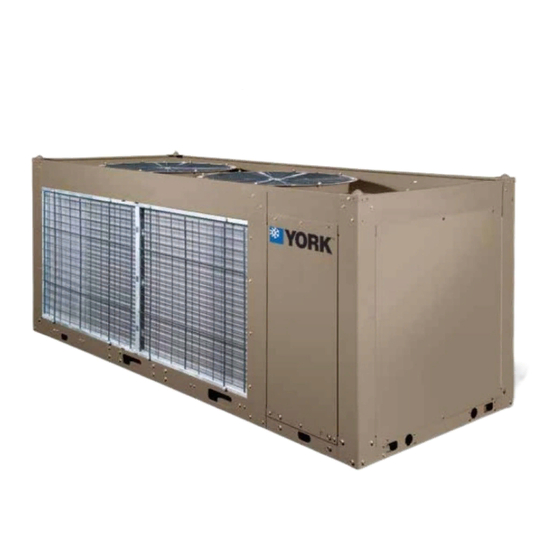
FORM 150.66-NM2 SECTION 2 - PRODUCT DESCRIPTION ISSUE DATE: 09/25/2020 UNIT COMPONENTS FAN ASSEMBlIES CONTROl / POWER PANEl CONDENSER COIlS hEAT EXChANGER COMPRESSORS FIG. 1 – UNIT COMPONENTS JOHNSON CONTROLS... -
Page 24: Control / Power Panel Components
FORM 150.66-NM2 SECTION 2 - PRODUCT DESCRIPTION ISSUE DATE: 09/25/2020 CONTROL / POWER PANEL COMPONENTS CIRCUIT BREAKER UNIT SWITCh KEyPAD AND DISPlAy COMPRESSOR CONTACTORS USER TERMINAl BlOCK FIG. 2 – CONTROL/POWER PANEL COMPONENTS JOHNSON CONTROLS... -
Page 25: Product Identification Number (Pin)
14 15 BASE PRODUCT TyPE NOMINAl CAPACITy UNIT DESIGNATOR REFRIGERANT VOlTAGE/STARTER DESIGN/DEVElOPMENT lEVEl : R-410A : yORK : High Efficiency : 200 / 3/ 60 : Design Series A : Chiller : 230 / 3 / 60 : Engineering : Air-Cooled... - Page 26 FORM 150.66-NM2 SECTION 2 - PRODUCT DESCRIPTION ISSUE DATE: 09/25/2020 PRODUCT IDENTIFICATION NUMBER (PIN) (CON’T) FEATURE DESCRIPTION OPTION DESCRIPTION No Control Transformer Required TRANS Cntrl Transformer (PIN 18) Control Transformer Required Special Control Transformer Re- quired No Power Capacitor Required Power Factor Capacitor (PIN 19) Power Capacitor Required Special Power Capacitor Required...
- Page 27 FORM 150.66-NM2 SECTION 2 - PRODUCT DESCRIPTION ISSUE DATE: 09/25/2020 PRODUCT IDENTIFICATION NUMBER (PIN) (CON’T) FEATURE DESCRIPTION OPTION DESCRIPTION No Chicago Code Kit Required Chicago Code Kit Required CHICAGO Chicago Code Kit (PIN 31) Service Isolation Valves Both Chicago Code & Serv Isolation Special Chicago Code Kit Required Standard Valves Required VALVES...
- Page 28 FORM 150.66-NM2 SECTION 2 - PRODUCT DESCRIPTION ISSUE DATE: 09/25/2020 PRODUCT IDENTIFICATION NUMBER (PIN) (CON’T) FEATURE DESCRIPTION OPTION DESCRIPTION Ul Pressure Code Vessel VESSEL Vessel Codes (PIN 42) ASME Pressure Vessel Code Special Pressure Vessel Code Standard Cooler Required Cooler (PIN 43) Remote Cooler Required Special Cooler Required No Option Required...
- Page 29 FORM 150.66-NM2 SECTION 2 - PRODUCT DESCRIPTION ISSUE DATE: 09/25/2020 PRODUCT IDENTIFICATION NUMBER (PIN) (CON’T) FEATURE DESCRIPTION OPTION DESCRIPTION 1st year Parts Only 1st year Parts & labor 2nd year Parts Only 2nd Parts & labor WARRANTY Warranty (PIN 55) 5 year Compressor Parts Only 5 year Compressor Parts &...
-
Page 30: Refrigerant Flow Diagram
FORM 150.66-NM2 SECTION 2 - PRODUCT DESCRIPTION ISSUE DATE: 09/25/2020 REFRIGERANT FLOW DIAGRAM AIR COOlED CONDENSERS hOT DISChARGE GAS lINE “OPTIONAl” “OPTIONAl” DISChARGE lINE BAll VAlVE “OPTIONAl” “OPTIONAl” SERVICE VAlVE “OPTIONAl” “OPTIONAl” “OPTIONAl” lD11417A FIG. 3 – REFRIGERANT FLOW DIAGRAM JOHNSON CONTROLS... -
Page 31: Section 3 - Handling And Storage
If any damage is evident, it should be noted on the carrier’s freight bill and a claim entered in accordance with the instructions given on the advice note. Major damage must be reported immediately to your local YORK representative. JOHNSON CONTROLS... -
Page 32: Unit Rigging
FORM 150.66-NM2 SECTION 3 - hANDlING AND STORAGE ISSUE DATE: 09/25/2020 Unit Rigging Lifting Instructions are placed on a label on the chiller and on the shipping bag. lD11837 lD11838 Forks must extend beyond the width of the unit for proper lift. The thick ness of the fork blade must be smaller then the opening of the lifting hole. -
Page 33: Section 4 - Installation
To ensure warranty coverage, this equipment must be commissioned These units are shipped as completely assembled units and serviced by an authorized YORK containing full operating charge, and care should be service mechanic or a qualified service taken to avoid damage due to rough handling. -
Page 34: Foundation
Considerations should be made utilizing noise levels Hand stop valves should be installed in all lines to fa- cilitate servicing. published in the YORK Engineering Guide for the specific chiller model. Sound blankets for the Piping to the inlet and outlet connections of the chiller compressors and low sound fans are available. -
Page 35: Duct Work Connection
WIRING Liquid Chillers are shipped with all factory-mounted 7. A chilled water flow switch, (either by YORK or controls wired for operation. others) MUST be installed in the leaving water piping of the cooler. There should be a straight Field Wiring –... -
Page 36: Evaporator Pump Start Contacts
FORM 150.66-NM2 SECTION 4 - INSTAllATION ISSUE DATE: 09/25/2020 A 120-1-60, 15 A source must be supplied for the control Remote Emergency Cutoff panel through a fused disconnect when a control panel transformer (optional) is not provided (refer to FIG. 5). Immediate shutdown of the chiller can be accomplished by opening a field-installed dry contact to break the elec- See the unit wiring diagrams for field and power wiring... -
Page 37: Single Point Supply Connection
FORM 150.66-NM2 SECTION 4 - INSTAllATION ISSUE DATE: 09/25/2020 SINGLE-POINT SUPPLY CONNECTION – TERMINAL BLOCK, NON-FUSED DISCONNECT SWITCH OR CIRCUIT BREAKER (0012 - 0032) Power Panel Power Panel Power Panel Control Panel Control Panel Control Panel Terminal Block, Terminal Block, MICROPANEL MICROPANEL NF Disconnect SW... -
Page 38: Control Wiring
FORM 150.66-NM2 SECTION 4 - INSTAllATION ISSUE DATE: 09/25/2020 CONTROL WIRING FLOW SW REMOTE START/STOP PWM INPUT LOAD LIMIT INPUT CTB1 lD07725 * Factory wired with optional transformer. lD07730B It is possible that multiple sources of power can be supplying the unit power panel. To pre vent serious injury or death, the technician should verify that NO LETHAL VOLTAGES are present inside the panel AFTER disconnecting power, PRIOR to working on equipment. -
Page 39: Section 5 - Commissioning
Compressor Oil only be carried out by YORK Autho rized personnel. To add oil to a circuit - connect a YORK hand oil pump (Part No. 470-10654-000) to the 1/4 in. oil charging valve on the oil separator piping with a length of clean hose or copper line, but do not tighten the flare nut. -
Page 40: Supply Voltage
FORM 150.66-NM2 SECTION 5 - COMMISSIONING ISSUE DATE: 09/25/2020 Supply Voltage Water System Verify that the site voltage supply corresponds to the Verify the chilled liquid system has been installed unit requirement and is within the limits given in the correctly, and has been commissioned with the correct Technical Data Section. -
Page 41: Equipment Startup Checklist
FORM 150.66-NM2 SECTION 5 - COMMISSIONING ISSUE DATE: 09/25/2020 EQUIPMENT STARTUP CHECKLIST 7. Check the control panel to ensure it is free of JOB NAME: ______________________________ foreign material (wires, metal chips, etc.). SALES ORDER #: _________________________ 8. Visually inspect wiring (power and control). Wir- LOCATION: ______________________________ ing MUST meet N.E.C. -
Page 42: Setpoints Entry List
FORM 150.66-NM2 SECTION 5 - COMMISSIONING ISSUE DATE: 09/25/2020 The chilled liquid setpoint may need TABLE 1 – SETPOINTS ENTRY LIST to be temporarily lowered to ensure OPTIONS Display language all compressors cycle “on.” Sys 1 Switch Chilled liquid * Ambient Control local/Remote Mode Control Mode This unit uses scroll compressors... -
Page 43: Checking Superheat And Subcooling
FORM 150.66-NM2 SECTION 5 - COMMISSIONING ISSUE DATE: 09/25/2020 CHECKING SUPERHEAT AND SUBCOOLING When adjusting the expansion valve (TXV only), the The subcooling temperature of each system can be calculated by recording the temperature of the liquid adjusting screw should be turned not more than one line at the outlet of the condenser and subtracting it from turn at a time, allowing sufficient time (approximately the liquid line saturation temperature at the liquid stop... -
Page 44: Unit Operating Sequence
FORM 150.66-NM2 SECTION 5 - COMMISSIONING ISSUE DATE: 09/25/2020 UNIT OPERATING SEQUENCE The operating sequence described below relates to 4. Several seconds after the compressor starts, that systems first condenser fan will be cycled on (out- operation on a hot water start after power has been door air temperature >... -
Page 45: Section 6 - Technical Data
1. For leaving brine temperature below 40°F (4.4°C), contact your nearest YORK Office for application requirements. 2. For leaving water temperature higher than 55°F (12.8°C), contact the nearest YORK Office for application guidelines. 3. The evaporator is protected against freezing to -20°F (-28.8°C) with an electric heater as standard. -
Page 46: Ethylene Glycol Correction Factors
FORM 150.66-NM2 SECTION 6 - TEChNICAl DATA ISSUE DATE: 09/25/2020 OPERATIONAL LIMITATIONS (ENGLISH) ENGLISH 1000.0 100.0 10.0 1000 FLOW, GPM HEAT EXCHANGER FLOW, GPM lD10955 MODEL YCAL COOLER CURVE YCAL0012 YCAL0018 YCAL0021 YCAL0027/0025 YCAL0032 TABLE 4 – ETHYLENE GLYCOL CORRECTION FACTORS % WT FACTORS FREEZE... -
Page 47: Operational Limitations (Si)
1. For leaving brine temperature below 40°F (4.4°C), contact your nearest YORK Office for application requirements. 2. For leaving water temperature higher than 55°F (12.8°C), contact the nearest YORK Office for application guidelines. 3. The evaporator is protected against freezing to -20°F (-28.8°C) with an electric heater as standard. -
Page 48: Ethylene Glycol Correction Factors
FORM 150.66-NM2 SECTION 6 - TEChNICAl DATA ISSUE DATE: 09/25/2020 OPERATIONAL LIMITATIONS (SI) 1000.0 100.0 10.0 FLOW, L/S HEAT EXCHANGER FLOW, L/S lD10956 MODEL YCAL COOLER CURVE YCAL0012 YCAL0018 YCAL0021 YCAL0027/0025 YCAL0032 TABLE 7 – ETHYLENE GLYCOL CORRECTION FACTORS % WT FACTORS FREEZE ETHYLENE... -
Page 49: Physical Data (English)
FORM 150.66-NM2 SECTION 6 - TEChNICAl DATA ISSUE DATE: 09/25/2020 PHYSICAL DATA (ENGLISH) YCAL0012_ - YCAL0032_ TABLE 8 – PHYSICAL DATA (ENGLISH) 60Hz Dimension General Unit Data (No Pump Models) Nominal Compr Capacity Shipping Operating Model Refrigerant Nominal Weight * Weight * Number of Charge,... -
Page 50: Sound Data (English)
FORM 150.66-NM2 SECTION 6 - TEChNICAl DATA ISSUE DATE: 09/25/2020 SOUND DATA (ENGLISH) YCAL0012_ - YCAL0032_ TABLE 9 – SOUND DATA (ENGLISH) 60 Hz Line Frequency LOW NOISE FAN (STANDARD) 1000 2000 4000 8000 YCAL0012 YCAL0018 YCAL0021 YCAL0025 YCAL0027 YCAL0032 60 Hz Line Frequency LOW NOISE FAN WITH COMPRESSOR SOUND BLANKETS 1000... - Page 51 FORM 150.66-NM2 SECTION 6 - TEChNICAl DATA ISSUE DATE: 09/25/2020 THIS PAGE INTENTIONALLY LEFT BLANK JOHNSON CONTROLS...
-
Page 52: Electrical Data (English)
Dual Element Fuse Circuit Breaker Terminal- Volt/ Lug/ Model Ampacity Non Fused Block Lug 60 Hz Phase (MCA) Disconnect Wire Range #14-2/0 #14-2/0 #14-2/0 YCAL0012EC #14-2/0 #14-2/0 #14-2/0 #14-2/0 YCAL0018EC #14-2/0 #14-2/0 #14-2/0 #14-2/0 #14-2/0 YCAL0021EC #14-2/0 #14-2/0 #14-2/0 #14-2/0 #14-2/0... - Page 53 FORM 150.66-NM2 SECTION 6 - TEChNICAl DATA ISSUE DATE: 09/25/2020 ELECTRICAL DATA YCAL0012 - 0032 (ENGLISH) (CON’T) SINGlE POINT FIElD SUPPlIED POWER WIRING (See FIG. 5) (One Field Provided Power Supply to the chiller. Field connections to Factory Provided Power Terminal Block (standard), Non-Fused Discon- nect Switch (optional) or Circuit Breaker (optional)).
-
Page 54: Table 11 - Micro Panel Power Supply
FORM 150.66-NM2 SECTION 6 - TEChNICAl DATA ISSUE DATE: 09/25/2020 ELECTRICAL DATA TABLE 11 – MICRO PANEL POWER SUPPLY OVER CURRENT PROTECTION, CONTROL UNIT VOLTAGE SEE NOTE B NF DISC SW POWER NOTE A UNIT MODELS w/o VOLTAGE CONTROL 115-1-60/50 30 A / 240V TRANS 200-1-60... -
Page 55: Electrical Notes And Legend
FORM 150.66-NM2 SECTION 6 - TEChNICAl DATA ISSUE DATE: 09/25/2020 ELECTRICAL NOTES AND LEGEND NOTES: 1. Minimum Circuit Ampacity (MCA) is based on 125% of the rated load amps for the largest motor plus 100% of the rated load amps for all other loads included in the circuit, per N.E.C. Article 430-24. If the optional Factory Mounted Control Transformer is provided, add the following MCA values to the electrical tables for the system providing power to the transformer: -17, add 2.5 amps;... -
Page 56: Fig. 7 - Control Circuit, Single
FORM 150.66-NM2 SECTION 6 - TEChNICAl DATA ISSUE DATE: 09/25/2020 ELEMENTARY DIAGRAM 0012 - 0032 STANDARD LOW SOUND ULTRA LOW SOUND, 460V lD13257 FIG. 7 – CONTROL CIRCUIT, SINGLE JOHNSON CONTROLS... - Page 57 FORM 150.66-NM2 SECTION 6 - TEChNICAl DATA ISSUE DATE: 09/25/2020 ELEMENTARY DIAGRAM (CON’T) lD13258 JOHNSON CONTROLS...
-
Page 58: Fig. 8 - Control Circuit, Single
FORM 150.66-NM2 SECTION 6 - TEChNICAl DATA ISSUE DATE: 09/25/2020 ELEMENTARY DIAGRAM 0025 - 0032 ULTRA LOW SOUND, 200V, 230V, 380V & 575V lD11799 FIG. 8 – CONTROL CIRCUIT, SINGLE JOHNSON CONTROLS... - Page 59 FORM 150.66-NM2 SECTION 6 - TEChNICAl DATA ISSUE DATE: 09/25/2020 ELEMENTARY DIAGRAM (CON’T) lD12241 JOHNSON CONTROLS...
-
Page 60: Fig. 9 - Power Circuit, Single
FORM 150.66-NM2 SECTION 6 - TEChNICAl DATA ISSUE DATE: 09/25/2020 ELEMENTARY DIAGRAM 0012 - 0032 STANDARD LOW SOUND 0025 - 0032 ULTRA LOW SOUND, 460V lD13256 FIG. 9 – POWER CIRCUIT, SINGLE JOHNSON CONTROLS... -
Page 61: Fig. 10 - Power Circuit, Single
FORM 150.66-NM2 ELEMENTARY DIAGRAM SECTION 6 - TEChNICAl DATA ISSUE DATE: 09/25/2020 0025 - 0032 ULTRA LOW SOUND, 200V, 230V, 380V & 575V lD13265 FIG. 10 – POWER CIRCUIT, SINGLE JOHNSON CONTROLS... -
Page 62: Fig. 11 - Connection Diagram
FORM 150.66-NM2 SECTION 6 - TEChNICAl DATA ISSUE DATE: 09/25/2020 CONNECTION DIAGRAM 0012 - 0032 STANDARD LOW SOUND 0025 - 0032 ULTRA LOW SOUND, 460V lD13254 FIG. 11 – CONNECTION DIAGRAM JOHNSON CONTROLS... -
Page 63: Fig. 12 - Connection Diagram
FORM 150.66-NM2 SECTION 6 - TEChNICAl DATA ISSUE DATE: 09/25/2020 CONNECTION DIAGRAM 0025 - 0032 ULTRA LOW SOUND, 200V, 230V, 380V & 575V lD13266 FIG. 12 – CONNECTION DIAGRAM JOHNSON CONTROLS... -
Page 64: Fig. 13 - Connection Diagram
FORM 150.66-NM2 SECTION 6 - TEChNICAl DATA ISSUE DATE: 09/25/2020 CONNECTION DIAGRAM 0012 - 0032 ALL UNITS lD13253 FIG. 13 – CONNECTION DIAGRAM JOHNSON CONTROLS... -
Page 65: Fig. 14 - Connection Diagram - Standard Unit
FORM 150.66-NM2 SECTION 6 - TEChNICAl DATA ISSUE DATE: 09/25/2020 CONNECTION DIAGRAM ALL MODELS BACNET MICROGATEWAY OPTION lD11796A FIG. 14 – CONNECTION DIAGRAM - STANDARD UNIT JOHNSON CONTROLS... - Page 66 Site restrictions may compromise minimum clearances indicated below, resulting in unpredictable airflow patterns and possible diminished performance. yORK’s unit controls will optimize operation without nuisance high-pressure safety cutouts; however, the system designer must consider potential performance degradation. Recommended minimum clearances: front to wall – 6';...
- Page 67 FORM 150.66-NM2 SECTION 6 - TEChNICAl DATA ISSUE DATE: 09/25/2020 DIMENSIONS - YCAL0012 (ENGLISH) (CON’T) 9/16" DIA MOUNTING HOLES(typ) 1 1/16" CONTROL COMPR PANEL 44 3/8" END CAP WIDTH 32 1/8" 6 1/8" 1 1/16" ORIGIN 2 1/4" 5" TOP VIEW 17"...
-
Page 68: Dimensions
Site restrictions may compromise minimum clearances indicated below, resulting in unpredictable airflow patterns and possible diminished performance. yORK’s unit controls will optimize operation without nuisance high-pressure safety cutouts; however, the system designer must consider potential performance degradation. Recommended minimum clearances: front to wall – 6';... - Page 69 FORM 150.66-NM2 SECTION 6 - TEChNICAl DATA ISSUE DATE: 09/25/2020 DIMENSIONS - YCAL0018 (ENGLISH) (CON’T) 9/16" DIA MOUNTING HOLES(typ) 1 1/16" CONTROL COMPR PANEL 44 3/8" END CAP WIDTH 32 1/8" 6 1/8" 1 1/16" ORIGIN 2 1/4" 5" TOP VIEW 17"...
- Page 70 Site restrictions may compromise minimum clearances indicated below, resulting in unpredictable airflow patterns and possible diminished performance. yORK’s unit controls will optimize operation without nuisance high-pressure safety cutouts; however, the system designer must consider potential performance degradation. Recommended minimum clearances: front to wall – 6';...
- Page 71 FORM 150.66-NM2 SECTION 6 - TEChNICAl DATA ISSUE DATE: 09/25/2020 DIMENSIONS - YCAL0021 (ENGLISH) (CON’T) 9/16" DIA MOUNTING HOLES(typ) 1 1/16" CONTROL COMPR PANEL 44 3/8" END CAP WIDTH 32 1/8" 6 1/8" 1 1/16" ORIGIN 2 1/4" 5" TOP VIEW 17"...
- Page 72 Site restrictions may compromise minimum clearances indicated below, resulting in unpredictable airflow patterns and possible diminished performance. yORK’s unit controls will optimize operation without nuisance high-pressure safety cutouts; however, the system designer must consider potential performance degradation. Recommended minimum clearances: front to wall – 6';...
- Page 73 FORM 150.66-NM2 SECTION 6 - TEChNICAl DATA ISSUE DATE: 09/25/2020 DIMENSIONS - YCAL0025 (ENGLISH) (CON’T) 9/16" DIA MOUNTING HOLES(typ) 1 1/16" CONTROL COMPR PANEL 44 3/8" END CAP WIDTH 32 1/8" 6 1/8" 1 1/16" 1 7/8" ORIGIN 5" 17" TOP VIEW 1"...
- Page 74 Site restrictions may compromise minimum clearances indicated below, resulting in unpredictable airflow patterns and possible diminished performance. yORK’s unit controls will optimize operation without nuisance high-pressure safety cutouts; however, the system designer must consider potential performance degradation. Recommended minimum clearances: front to wall – 6';...
- Page 75 FORM 150.66-NM2 SECTION 6 - TEChNICAl DATA ISSUE DATE: 09/25/2020 DIMENSIONS - YCAL0027 (ENGLISH) (CON’T) 9/16" DIA MOUNTING HOLES(typ) 1 1/16" CONTROL COMPR PANEL 44 3/8" END CAP WIDTH 32 1/8" 6 1/8" 1 1/16" 1 7/8" ORIGIN 5" 17" TOP VIEW 1"...
- Page 76 Site restrictions may compromise minimum clearances indicated below, resulting in unpredictable airflow patterns and possible diminished performance. yORK’s unit controls will optimize operation without nuisance high-pressure safety cutouts; however, the system designer must consider potential performance degradation. Recommended minimum clearances: front to wall – 6';...
- Page 77 FORM 150.66-NM2 SECTION 6 - TEChNICAl DATA ISSUE DATE: 09/25/2020 DIMENSIONS - YCAL0032 (ENGLISH) (CON’T) 9/16" DIA MOUNTING HOLES(typ) 1 1/16" CONTROL COMPR PANEL 44 3/8" END CAP WIDTH 32 1/8" 6 1/8" 1 1/16" 1 7/8" ORIGIN 5" 17" TOP VIEW 1"...
- Page 78 Site restrictions may compromise minimum clearances indicated below, resulting in unpredictable airflow patterns and possible diminished performance. yORK’s unit controls will optimize operation without nuisance high-pressure safety cutouts; however, the system designer must consider potential performance degradation. Recommended minimum clearances: front to wall – 2m;...
- Page 79 FORM 150.66-NM2 SECTION 6 - TEChNICAl DATA ISSUE DATE: 09/25/2020 DIMENSIONS - YCAL0012 (SI) (CON’T) 14 DIA MOUNTING HOLES(typ) CONTROL COMPR PANEL 1128 END CAP WIDTH ORIGIN TOP VIEW CONTROL PANEL (2) 178 X 57 FORKLIFT HOLES (2) 76 X 38 BOTH SIDES RIGGING HOLES BOTH SIDES...
- Page 80 Site restrictions may compromise minimum clearances indicated below, resulting in unpredictable airflow patterns and possible diminished performance. yORK’s unit controls will optimize operation without nuisance high-pressure safety cutouts; however, the system designer must consider potential performance degradation. Recommended minimum clearances: front to wall – 2m;...
- Page 81 FORM 150.66-NM2 SECTION 6 - TEChNICAl DATA ISSUE DATE: 09/25/2020 DIMENSIONS - YCAL0018 (SI) (CON’T) 14 DIA MOUNTING HOLES(typ) CONTROL COMPR PANEL 1128 END CAP WIDTH ORIGIN TOP VIEW CONTROL PANEL (2) 178 X 57 FORKLIFT HOLES BOTH SIDES (2) 76 X 38 RIGGING HOLES BOTH SIDES 1130...
- Page 82 Site restrictions may compromise minimum clearances indicated below, resulting in unpredictable airflow patterns and possible diminished performance. yORK’s unit controls will optimize operation without nuisance high-pressure safety cutouts; however, the system designer must consider potential performance degradation. Recommended minimum clearances: front to wall – 2m;...
- Page 83 FORM 150.66-NM2 SECTION 6 - TEChNICAl DATA ISSUE DATE: 09/25/2020 DIMENSIONS - YCAL0021 (SI) (CON’T) 14 DIA MOUNTING HOLES(typ) CONTROL COMPR PANEL 1128 END CAP WIDTH ORIGIN TOP VIEW (2) 178 X 57 FORKLIFT HOLES BOTH SIDES (2) 76 X 38 RIGGING HOLES BOTH SIDES 1130...
- Page 84 Site restrictions may compromise minimum clearances indicated below, resulting in unpredictable airflow patterns and possible diminished performance. yORK’s unit controls will optimize operation without nuisance high-pressure safety cutouts; however, the system designer must consider potential performance degradation. Recommended minimum clearances: front to wall – 2m;...
- Page 85 FORM 150.66-NM2 SECTION 6 - TEChNICAl DATA ISSUE DATE: 09/25/2020 DIMENSIONS - YCAL0025 (SI) (CON’T) 14 DIA MOUNTING HOLES(typ) CONTROL COMPR PANEL 1128 END CAP WIDTH ORIGIN TOP VIEW CONTROL PANEL 1070 (2) 178 X 57 FORKLIFT HOLES BOTH SIDES (2) 76 X 38 RIGGING HOLES 1282...
- Page 86 Site restrictions may compromise minimum clearances indicated below, resulting in unpredictable airflow patterns and possible diminished performance. yORK’s unit controls will optimize operation without nuisance high-pressure safety cutouts; however, the system designer must consider potential performance degradation. Recommended minimum clearances: front to wall – 2m;...
- Page 87 FORM 150.66-NM2 SECTION 6 - TEChNICAl DATA ISSUE DATE: 09/25/2020 DIMENSIONS - YCAL0027 (SI) (CON’T) 14 DIA MOUNTING HOLES(typ) CONTROL COMPR PANEL 1128 END CAP WIDTH ORIGIN TOP VIEW CONTROL PANEL 1070 (2) 178 X 57 FORKLIFT HOLES BOTH SIDES (2) 76 X 38 RIGGING HOLES 1282...
- Page 88 Site restrictions may compromise minimum clearances indicated below, resulting in unpredictable airflow patterns and possible diminished performance. yORK’s unit controls will optimize operation without nuisance high-pressure safety cutouts; however, the system designer must consider potential performance degradation. Recommended minimum clearances: front to wall – 2m;...
- Page 89 FORM 150.66-NM2 SECTION 6 - TEChNICAl DATA ISSUE DATE: 09/25/2020 DIMENSIONS - YCAL0032 (SI) (CON’T) 14 DIA MOUNTING HOLES(typ) CONTROL COMPR PANEL 1128 END CAP WIDTH ORIGIN TOP VIEW CONTROL PANEL 1070 (2) 178 X 57 FORKLIFT HOLES BOTH SIDES (2) 76 X 38 RIGGING HOLES 1282...
-
Page 90: Technical Data - Clearances
FORM 150.66-NM2 SECTION 6 - TEChNICAl DATA ISSUE DATE: 09/25/2020 TECHNICAL DATA - CLEARANCES (1.3 m) (2 m) lD10506 NOTES: 1. No obstructions allowed above the unit. 2. Only one adjacent wall may be higher than the unit. 3. Adjacent units should be 10 ft (3 m) apart. FIG. -
Page 91: Isolators
FORM 150.66-NM2 SECTION 6 - TEChNICAl DATA ISSUE DATE: 09/25/2020 ISOLATOR SELECTION (WITHOUT PUMP PACKAGE OPTION) Standard Aluminum Condenser Fins Optional Copper Condenser Fins location 1” Deflection CIP-B-450 CIP-B-750 CIP-B-450 CIP-B-750 CIP-B-450 CIP-B-750 CIP-B-450 CIP-B-750 Neoprene ND-C ND-C ND-C ND-C ND-C ND-C ND-C... - Page 92 YORK sales office. and kilograms at the specific location, isolator position, Be aware, weights may change with each option along and location measurements for each isolator.
- Page 93 11.1 165.1 38.1 155.5 133.3 Weight Range Weight Range Model Number Color YORK P/N (lbs) (kg) 239 to 384 lbs 108 to 174 kg CIP - B - 450 029-24583-002 384 to 639 lbs 174 to 290 kg CIP - B - 750...
- Page 94 FORM 150.66-NM2 SECTION 6 - TEChNICAl DATA ISSUE DATE: 09/25/2020 INSTALLATION OF 1 IN. DEFLECTION MOUNTS 5. Complete piping and fill equipment with water, refrigerant, etc. 1. Floor or steel frame should be level and smooth. 6. Turn leveling bolt of first isolator four full revolu- 2.
- Page 95 1/2- 13 x 1” 1/ 2" ND-C 65.1 69.9 139.7 58.7 101.9 1/2- 13 x 1” 1/ 2" Weight Range Weight Range Model Number Color YORK P/N (lbs) (kg) Up to 751 lbs Up to 341 kg ND-C yellow 029-24585-006 JOHNSON CONTROLS...
- Page 96 HCW MBD 2-C2 215.9 15.9 34.9 355.6 311.2 133.4 88.9 5/8" *Weight Range Weight Range Model Number Color YORK P/N (lbs) (kg) Up to 358 lbs Up to 162 kg SlRS-2-C2- 029-24585-006 358 to 443 lbs 162 to 201 kg...
- Page 97 FORM 150.66-NM2 SECTION 6 - TEChNICAl DATA ISSUE DATE: 09/25/2020 SLRS SEISMIC ISOLATOR INSTALLATION AND ADJUSTMENT TO INSTAll AND ADJUST MOUNTS 1. Supports for mountings must be leveled to installation's acceptable tolerances. 2. Mountings not subjected to seismic or wind forces do not require bolting to supports. 3.
- Page 98 FORM 150.66-NM2 ISSUE DATE: 09/25/2020 THIS PAGE INTENTIONALLY LEFT BLANK JOHNSON CONTROLS...
-
Page 99: Section 7 - Unit Controls
YORK MILLENNIUM CONTROL CENTER 00065VIP INTRODUCTION MICROPROCESSOR BOARD The YORK MicroComputer Control Center is a The Microprocessor Board is the controller and microprocessor based control system designed to provide decision maker in the control panel. System inputs the entire control for the liquid chiller. The control logic such as pressure transducers and temperature sensors are connected directly to the Microprocessor Board. -
Page 100: Unit Switch
FORM 150.66-NM2 SECTION 7 - UNIT CONTROlS ISSUE DATE: 09/25/2020 UNIT SWITCH BATTERY BACK-UP A unit ON/OFF switch is just underneath the keypad. The Microprocessor Board contains a Real Time Clock This switch allows the operator to turn the entire unit integrated circuit chip with an internal battery backup. -
Page 101: Status" Key
FORM 150.66-NM2 SECTION 7 - UNIT CONTROlS ISSUE DATE: 09/25/2020 “STATUS” KEY 00066VIP UNIT STATUS R E M O T E C O N T R O L L E D S H U T D O W N Pressing the STATUS key will enable the operator to determine current chiller operating status. - Page 102 FORM 150.66-NM2 SECTION 7 - UNIT CONTROlS ISSUE DATE: 09/25/2020 The limiting pressure is a factory set limit to keep the S Y S C O O L L O A D system from faulting on the high discharge pressure cutout due to high load or pull down conditions.
-
Page 103: Fault Safety Status Messages
FORM 150.66-NM2 SECTION 7 - UNIT CONTROlS ISSUE DATE: 09/25/2020 S Y S P U M P I N G D O W N S Y S L O W S U C T P R E S S The PUMPING DOWN message indicates that a The Suction Pressure Cutout is a software cutout that compressor in the respective system is presently in the helps protect the chiller from an evaporator freeze-up... - Page 104 FORM 150.66-NM2 SECTION 7 - UNIT CONTROlS ISSUE DATE: 09/25/2020 The internal motor protector opens at 185°F - 248°F S Y S L O W E V A P T E M P (85°C - 120°C) and auto resets. The mechanical HP switch opens at 405 psig +/- 10 psig (27.92 barg +/- .69 barg) and closes at 330 psig +/- 25 psig (22.75 barg +/- 1.72 barg).
-
Page 105: Unit Safeties
FORM 150.66-NM2 SECTION 7 - UNIT CONTROlS ISSUE DATE: 09/25/2020 This safety will shut down a system if either suction U N I T F A U L T : temperature or suction pressure sensors read out of H I G H M T R C U R R range high or low. -
Page 106: Table 13 - Status Key Messages Quick Reference List
FORM 150.66-NM2 SECTION 7 - UNIT CONTROlS ISSUE DATE: 09/25/2020 STATUS KEY MESSAGES TABLE 13 – STATUS KEY MESSAGES QUICK REFERENCE LIST STATUS KEY MESSAGES General Messages Fault Messages Unit Safeties & System Safeties Unit Switch Off Warning Messages Shutdown Remote Controlled System X High Disch Pressure Low Ambient Temp... - Page 107 FORM 150.66-NM2 SECTION 7 - UNIT CONTROlS ISSUE DATE: 09/25/2020 DISPLAY/PRINT KEYS 00067VIP The Display/Print keys allow the user to retrieve system With the “UNIT TYPE” set as a liquid chiller (via no and unit information that is useful for monitoring jumper between J4-11 and J4-6), the following list of chiller operation, diagnosing potential problems, operating data screens are viewable under the Oper Data...
- Page 108 FORM 150.66-NM2 SECTION 7 - UNIT CONTROlS ISSUE DATE: 09/25/2020 Run times and starts will only be S Y S 7 2 . 1 P S I G displayed for the actual number of = 2 2 7 . 0 P S I G systems and compressors on the unit.
- Page 109 1, then for system 2. may be via ISN. The first message indicates the system and the associated ISN – YORK Talk via ISN allows remote load limiting compressors which are running. and temperature reset through an ISN system.
-
Page 110: Table 14 - Operation Data
FORM 150.66-NM2 SECTION 7 - UNIT CONTROlS ISSUE DATE: 09/25/2020 See the section on Condenser Fan Control in the UNIT TABLE 14 – OPERATION DATA OPERATION section for more information. Oper Data Key The fifth message displays current as sensed by the Leaving &... - Page 111 HOT GAS BYPASS VALVE printed for all models.) CONDENSER FAN STAGES EEV OUTPUT 0.0 % SYSTEM XXX.X AMPS X.X VOLTS YORK INTERNATIONAL CORPORATION MILLENNIUM LIQUID CHILLER DAILY SCHEDULE S M T W T F S *=HOLIDAY UNIT STATUS MON START=00:00AM...
- Page 112 L I Q U I D T E M P history print and the header will be as follows. Displays the type of fault that occurred. YORK INTERNATIONAL MILLENNIUM LIQUID CHILLER U N I T T Y P E SAFETY SHUTDOWN NUMBER 1...
- Page 113 FORM 150.66-NM2 SECTION 7 - UNIT CONTROlS ISSUE DATE: 09/25/2020 A M B I E N T C O N T R O L L O W A M B I E N T T E M P X X X X X X X X X X C U T O U T X X X .
- Page 114 FORM 150.66-NM2 SECTION 7 - UNIT CONTROlS ISSUE DATE: 09/25/2020 S Y S F A N S T A G E X X X E V A P P U M P X X X E V A P H E A T E R X X X Displays status of the Evaporator Pump and Heater at Displays the number of Fan Stages in the system active...
- Page 115 FORM 150.66-NM2 SECTION 7 - UNIT CONTROlS ISSUE DATE: 09/25/2020 “ENTRY” KEYS 00068VIP The Entry Keys allows the user to view, change programmed ENTER/ADV KEY values. The ENTRY keys consist of an ↑ (UP) arrow key, ↓ The ENTER/ADV key must be pushed after any change (DOWN) arrow key, and an ENTER/ADV key.
- Page 116 FORM 150.66-NM2 SECTION 7 - UNIT CONTROlS ISSUE DATE: 09/25/2020 “SETPOINTS” KEYS 00069VIP Programming of the cooling setpoints, daily schedule, LEAVING CHILLED LIQUID CONTROL and safeties is accomplished by using the keys located under the SETPOINTS section. S E T P O I N T 4 5 .
- Page 117 FORM 150.66-NM2 SECTION 7 - UNIT CONTROlS ISSUE DATE: 09/25/2020 When in leaving chilled liquid temperature control, the R E M S E T P 4 4 . 0 ° F micro will attempt to control the leaving water tem- R A N G E + / - 2 .
-
Page 118: Table 15 - Cooling Setpoints, Programmable Limits And Defaults
When using glycol, leaving Chilled liquid Setpoint should not be set below 20°F (-6.7°C). ** Do not exceed 55°F (12.8°C) setpoint before contacting the nearest yORK Office for application guidelines. The line under the 0 is the cursor. If the value is wrong,... - Page 119 FORM 150.66-NM2 SECTION 7 - UNIT CONTROlS ISSUE DATE: 09/25/2020 PROGRAM KEY There are several operating parameters under the L O W A M B I E N T T E M P PROGRAM key that are programmable. These setpoints C U T O U T 2 5 .
- Page 120 FORM 150.66-NM2 SECTION 7 - UNIT CONTROlS ISSUE DATE: 09/25/2020 The microprocessor will not allow This MUST be programmed correctly programming the “FAN CONTROL to ensure proper chiller operation. ON PRESSURE” minus the “FAN CONTROL DIFFERENTIAL OFF PRESSURE” below 160 psig. This ensures discharge pressure does not drop too low.
-
Page 121: Table 16 - Program Key Limits And Defaults
FORM 150.66-NM2 SECTION 7 - UNIT CONTROlS ISSUE DATE: 09/25/2020 UNIT TRIP VOLTS For total chiller high current trip programming on R E M O T E U N I T 460 VAC chillers: P R O G R A M M E D •... -
Page 122: Table 17 - Setpoints Quick Reference List
FORM 150.66-NM2 SECTION 7 - UNIT CONTROlS ISSUE DATE: 09/25/2020 TABLE 17 – SETPOINTS QUICK REFERENCE LIST Quick Reference Programming Chart Setpoints Section Cooling Setpoints Key Schedule/ Program Mode (press key to adv.) Advance Day Key (press enter to adv.) Local Leaving Mon. - Page 123 FORM 150.66-NM2 SECTION 7 - UNIT CONTROlS ISSUE DATE: 09/25/2020 “UNIT” KEYS 00070VIP OPTIONS KEY Turning a system off with its system There are many user programmable options under the OPTIONS key. The OPTIONS key is used to scroll switch allows a pumpdown to be per through the list of options by repeatedly pressing the formed prior to shutdown.
- Page 124 FORM 150.66-NM2 SECTION 7 - UNIT CONTROlS ISSUE DATE: 09/25/2020 Option 4 – Ambient Control Type: C O N T R O L M O D E A M B I E N T C O N T R O L L E A V I N G L I Q U I D S T A N D A R D...
- Page 125 FORM 150.66-NM2 SECTION 7 - UNIT CONTROlS ISSUE DATE: 09/25/2020 This mode should be selected when an optional 2ACE module is installed to allow individual current F A N C O N T R O L monitoring of each system. . A M B I E N T &...
- Page 126 DO NOT reset or power down the chiller until the update When YORK HYDRO KIT PUMPS = 1, the controls is completed. will be closed to run the pumps whenever any one of...
- Page 127 The displays for this PUMP SELECTION option should time the day will be accepted and the cursor will move only appear if “YORK HYDRO KIT PUMPS = 2” are under the first digit of the “2 digit hour”. In a similar selected under Option 18.
-
Page 128: Table 18 - Unit Keys Programming Quick Reference List
FORM 150.66-NM2 SECTION 7 - UNIT CONTROlS ISSUE DATE: 09/25/2020 TABLE 18 – UNIT KEYS PROGRAMMING QUICK REFERENCE LIST (YCAL0012 - 0032 ONLY) (YCAL0012 - 0032 ONLY) Unit Type ("Chiller" MUST be Selected Via No Jumper Installed) (Viewable Only) R-410A or R-407C (Programmed under Service Mode) (Viewable Only) (Programmed under Service Mode) - Page 129 FORM 150.66-NM2 ISSUE DATE: 09/25/2020 SECTION 8 - UNIT OPERATION CAPACITY CONTROL LEAVING CHILLED LIQUID CONTROL To initiate the start sequence of the chiller, all run The setpoint, when programmed for Leaving Chilled permissive inputs must be satisfied (flow/remote start/ Liquid Control, is the temperature the unit will control stop switch), and no chiller or system faults exist.
-
Page 130: Fig. 16A - Leaving Water Temperature Control Example
FORM 150.66-NM2 SECTION 8 - UNIT OPERATION ISSUE DATE: 09/25/2020 Hot gas, if present, will be the final step of capacity. Hot microprocessor will increase the setpoint high limit according to the chart below; with a maximum value gas is energized when only a single compressor is running allowed of 50°F (see FIG. - Page 131 FORM 150.66-NM2 SECTION 8 - UNIT OPERATION ISSUE DATE: 09/25/2020 ANTI-COINCIDENCE TIMER CONDENSER FAN CONTROL (YCAL0012 – YCAL0032 CHILLERS) Condenser fan operation must be programmed with Controls are present in software to ensure compressors the Options key under “Fan Control.” Condenser fan within a circuit, do not start simultaneously.
-
Page 132: Table 19 - Ycal0012 - Ycal0032 Condenser Fan Control Using Outdoor
FORM 150.66-NM2 SECTION 8 - UNIT OPERATION ISSUE DATE: 09/25/2020 STANDARD CONDENSER FAN CONTROL - YCAL0012 – YCAL0032 TABLE 19 – YCAL0012 – YCAL0032 CONDENSER FAN CONTROL USING OUTDOOR AMBIENT TEMPERATURE AND DISCHARGE PRESSURE (DISCHARGE PRESSURE CONTROLS WILL NOT FUNCTION AND FAN CONTROL WILL BE BASED ON AMBIENT TEMPERATURES ONLY, UNLESS THE OPTIONAL DISCHARGE PRESSURE TRANSDUCER IS INSTALLED). -
Page 133: Fig. 17 - Typical Vfd Location
FORM 150.66-NM2 SECTION 8 - UNIT OPERATION ISSUE DATE: 09/25/2020 LOW AMBIENT FAN CONTROL OPTION The VFD control signal is sent from a liquid temperature YCAL 0012 - 0021 UNITS sensor connected to a condenser coil return bend. The sensor is connected to S1 and COM terminals of the General VFD in the control panel. -
Page 134: Fig. 20 - Wiring
FORM 150.66-NM2 SECTION 8 - UNIT OPERATION ISSUE DATE: 09/25/2020 Wiring VFD wiring is simple and requires only single phase power in, single phase power out and a 2-wire signal from the liquid line temperature sensor. No start, stop or other alternate power requirements are needed to operate the VFD. -
Page 135: Table 21 - Ycal0012 - 0021 Vfd Low Ambient Option - Condenser Fan
FORM 150.66-NM2 SECTION 8 - UNIT OPERATION ISSUE DATE: 09/25/2020 PROGRAMMING YCAL0012 - 0021 Condenser fan control type must be programmed under both the OPTIONS and PROGRAM keys when a VFD is installed on the chiller. Under the OPTIONS key, FAN CONTROL must be programmed for DISCHARGE PRESSURE CONTROL only. -
Page 136: Fig. 21 - Typical Vfd Enclosure Locations
FORM 150.66-NM2 SECTION 8 - UNIT OPERATION ISSUE DATE: 09/25/2020 If discharge pressure falls, the chiller microprocessor LOW AMBIENT FAN CONTROL OPTION YCAL0025-0032 UNITS will turn the second fan off by de-energizing the fan contactor. If pressure continues to fall, VFD speed will decrease in an effort to maintain discharge pressure. -
Page 137: Fig. 23 - Inverter Power Wiring Schematic
FORM 150.66-NM2 SECTION 8 - UNIT OPERATION ISSUE DATE: 09/25/2020 CONFIGURATION (JUMPERS AND POTENTIOMETER SETTINGS POTENTIOMETERS) 180 PSI 20 PSI Each VFD is pre-configured at the factory prior to shipping and should be ready for operation when it arrives onsite. A quick check of the settings is recommended. -
Page 138: Fig. 25 - Inverter Wiring
FORM 150.66-NM2 SECTION 8 - UNIT OPERATION ISSUE DATE: 09/25/2020 152A 152A 151A 151A 150A 150A TO MICROBOARD (P4) TO MICROBOARD (P4) TO PANEL 7M TO PANEL 7M TO FAN #1 (EXISTING HARNESS) TO FAN #1 (EXISTING HARNESS) FIG. 25 – INVERTER WIRING lD11302a PROGRAMMING - YCAL 0025 - 0032 Under the PROGRAM key, the FAN CONTROL ON... -
Page 139: Table 23 - Compressor Operation - Load Limiting
FORM 150.66-NM2 SECTION 8 - UNIT OPERATION ISSUE DATE: 09/25/2020 A contact closure on the PWM Temp Reset input at LOAD LIMITING CTB1 terminals 13 - 20, will reset the chilled liquid setpoint based on the length of time the contacts remain Load Limiting is a feature that prevents the unit from closed. - Page 140 New Setpoint = 7.22°C + 6.67°C = 13.89°C reset must be suppressed to prevent possible component damage. Use YORK PN 03100808000 suppres sor. Max Reset Value is the “Max EMS-PWM Remote Temp. Reset” setpoint value described in the program ming section under Cooling Setpoints.
-
Page 141: Fig. 26 - Field And Factory Electrical Connections Optional Remote Temperature Reset Board
FORM 150.66-NM2 SECTION 8 - UNIT OPERATION ISSUE DATE: 09/25/2020 – 035-15961-000 lD03875a FIG. 26 – FIELD AND FACTORY ELECTRICAL CONNECTIONS OPTIONAL REMOTE TEMPERATURE RESET BOARD JOHNSON CONTROLS... - Page 142 FORM 150.66-NM2 ISSUE DATE: 09/25/2020 THIS PAGE INTENTIONALLY LEFT BLANK JOHNSON CONTROLS...
- Page 143 FORM 150.66-NM2 ISSUE DATE: 09/25/2020 SECTION 9 - SERVICE AND TROUBLESHOOTING Following is the order of outputs that will appear as the CLEARING HISTORY BUFFERS ENTER/ADV key is pressed: The history buffers may be cleared by pressing the HIS- SYS 1 COMP 1 STATUS TB7-2 IS: TORY key and then repeatedly pressing the UP arrow SYS 1 LLSV STATUS TB7-3 IS: key until you scroll past the last history buffer choice.
- Page 144 FORM 150.66-NM2 SECTION 9 - SERVICE AND TROUBlEShOOTING ISSUE DATE: 09/25/2020 Following is a list, in order of appearance: The analog inputs will display the input connection, DATA LOGGING MODE = : DO NOT MODIFY the temperature or pressure, and corresponding input DATA LOGGING TIMER = : DO NOT MODIFY voltage such as: SOFT START...
-
Page 145: Table 24 - Microboard Digital Inputs
FORM 150.66-NM2 SECTION 9 - SERVICE AND TROUBlEShOOTING ISSUE DATE: 09/25/2020 CONTROL INPUTS/OUTPUTS TABLE 26 – MICROBOARD ANALOG INPUTS J7-10 Sys 1 Suction Pressure Transducer Tables 24 through 27 are a quick reference list providing the connection points and a description of the inputs and Sys 1 low Pressure Switch outputs respectively. -
Page 146: Fig. 27 - Ipu Ii & I/O Layout
FORM 150.66-NM2 SECTION 9 - SERVICE AND TROUBlEShOOTING ISSUE DATE: 09/25/2020 I/O BOARD BOARD TB10 lD12721 lD12721 FIG. 27 – IPU II & I/O LAYOUT JOHNSON CONTROLS... -
Page 147: Table 28 - Outdoor Air Sensor Temperature/Voltage/Resistance Correlation
FORM 150.66-NM2 SECTION 9 - SERVICE AND TROUBlEShOOTING ISSUE DATE: 09/25/2020 CHECKING INPUTS AND OUTPUTS TABLE 28 – OUTDOOR AIR SENSOR TEMPERATURE/VOLTAGE/RESISTANCE CORRELATION Digital Inputs VOlTAGE Refer to the unit wiring diagram. All digital inputs are TEMP°F (Signal Input TEMP°C connected to J13 of the microboard. -
Page 148: Table 29 - Entering/Leaving Chilled Liquid Temp. Sensor, Cooler Inlet Temperature Sensor, And Suction Temperature Sensor: Temperature/Voltage Correlation
FORM 150.66-NM2 SECTION 9 - SERVICE AND TROUBlEShOOTING ISSUE DATE: 09/25/2020 TABLE 29 – ENTERING/LEAVING CHILLED LIQUID TEMP. SENSOR, COOLER INLET TEMPERATURE SENSOR, AND SUCTION TEMPERATURE SENSOR: TEMPERATURE/VOLTAGE CORRELATION VOlTAGE VOlTAGE TEMP°F (Signal Input TEMP°C TEMP°F (Signal Input TEMP°C to Return) to Return) 1.33 3.05... - Page 149 FORM 150.66-NM2 SECTION 9 - SERVICE AND TROUBlEShOOTING ISSUE DATE: 09/25/2020 Analog Inputs – Pressure V = (Pressure in psig x 0.006) + .5 Refer to the unit wiring diagram. Pressure inputs are V = (Pressure in BARG x 0.09) + .5 connected to the microboard on plugs J7 and J9.
-
Page 150: Fig. 28 - I/O Board Relay Contact Architecture
FORM 150.66-NM2 SECTION 9 - SERVICE AND TROUBlEShOOTING ISSUE DATE: 09/25/2020 The suction transducers have a range from 0 psig to Digital Outputs 400 psig (27.58 barg). The output will be linear from 0.5 VDC to 4.5 VDC over the 400 psig (27.58 barg) Refer to the unit wiring diagram and Fig. -
Page 151: Fig. 29 - Printer To Microboard Electrical Connections
A printout is obtained by pressing the “PRINT” key on The part number for the printer that is packaged the keypad and then pressing either the “OPER DATA” specifically for YORK is P/N 950915576. The cable key or “HISTORY” key. to connect the printer can either be locally assembled from the parts listed, or ordered directly from WEIGH- TRONIX under part number 287-040018. -
Page 152: Table 30 - Troubleshooting
4. Unplug connections at or pressure transducers. Microboard to isolate. 5. Defective IPU & I/O board 5. Replace Microboard. or Display board. Contact YORK Service before Replacing circuit Boards! “FLOW SWITCH/REM 1. No chilled liquid flow. 1. Check chilled liquid flow. - Page 153 FORM 150.66-NM2 SECTION 9 - SERVICE AND TROUBlEShOOTING ISSUE DATE: 09/25/2020 TROUBLESHOOTING (CONT’D) PROBLEM CAUSE SOLUTION “LOW SUCTION PRESSURE” 4. TXV defective. 4. Replace TXV. FAULT (CONT’D) 5. Reduced flow of chilled 5. Check GPM (See “Limita tions” liquid through the cooler in Installation section).
- Page 154 4. Compressor failure. 4. Diagnose cause of failure and replace. LACK OF COOLING EFFECT 1. Fouled evaporator surface. 1. Contact the local yORK low suction pressure will service representative. be observed. 2. Improper flow through the 2. Reduce flow to within chiller evaporator.
- Page 155 Note: at shutdown, the oil level can fall to the stores customer programmed setpoints. The Real Time bottom limit of the oil sight glass. Use YORK “F” oil Clock is a 128K bram, P/N 031-02565-000. The IPU when adding oil.
- Page 156 FORM 150.66-NM2 SECTION 10 - MAINTENANCE ISSUE DATE: 09/25/2020 OVERALL UNIT INSPECTION In addition to the checks listed on this page, periodic overall inspections of the unit should be accomplished to ensure proper equipment operation. Items such as loose hardware, component operation, refrigerant leaks, unusual noises, etc.
-
Page 157: Table 31 - Isn Received Data
FORM 150.66-NM2 SECTION 10 - MAINTENANCE ISSUE DATE: 09/25/2020 ISN CONTROL RECEIVED DATA (CONTROL DATA) TABLE 32 – ISN TRANSMITTED DATA The Middle Market receives 8 data values from the CHARACTER TYPE DATA ISN. The first 4 are analog values and the last 4 are PAGE digital values. - Page 158 FORM 150.66-NM2 SECTION 10 - MAINTENANCE ISSUE DATE: 09/25/2020 ISN CONTROL (CON’T) ABLE 32 – ISN TRANSMITTED DATA (CONT’D) CHARACTER TYPE DATA CHARACTER TYPE DATA PAGE PAGE Digital Spare Coded SyS 1 liquid line Coded Spare Digital Solenoid Valve or Coded EEV Pilot Solenoid Unit Control Mode...
-
Page 159: Table 33 - Isn Operational And Fault Codes
FORM 150.66-NM2 SECTION 10 - MAINTENANCE ISSUE DATE: 09/25/2020 ISN CONTROL (CON’T) TABLE 33 – ISN OPERATIONAL AND FAULT CODES P56/58 OPERATIONAL CODE P57/59 FAULT CODE NO ABNORMAl CONDITION NO FAUlT UNIT SWITCh OFF VAC UNDER VOlTAGE SySTEM SWITCh OFF lOW AMBIENT TEMPERATURE lOCK-OUT hIGh AMBIENT TEMPERATURE... - Page 160 FORM 150.66-NM2 SECTION 10 - MAINTENANCE ISSUE DATE: 09/25/2020 BACNET AND MODBUS DATA COMMUNICATION modified. Modification is accomplished by pressing Data can be read and in some cases modified using the PROGRAM, DOWN ARROW, DOWN ARROW, a serial communication BACnet or Modbus network DOWN ARROW, DOWN ARROW, and ENTER keys connection.
-
Page 161: Table 34 - Minimum, Maximum And Default Values
FORM 150.66-NM2 SECTION 10 - MAINTENANCE ISSUE DATE: 09/25/2020 The table below shows the minimum, maximum, and default values. TABLE 34 – MINIMUM, MAXIMUM AND DEFAULT VALUES DESCRIPTION MINIMUM MAXIMUM DEFAULT DE MODIFIER ADDRESS 41943 DE MODIFIER OFFSET P1 BAUD RATE 1200 76800 4800... - Page 162 FORM 150.66-NM2 SECTION 10 - MAINTENANCE ISSUE DATE: 09/25/2020 Chiller data that can be read and modified using specific Modbus Register Addresses; and the data associated with the addresses, is outlined in the following description: SERIAL COMMUNICATION ANALOG VALUE DATA This data can be read and modified using a BACnet or Modbus network connection.
- Page 163 FORM 150.66-NM2 SECTION 10 - MAINTENANCE ISSUE DATE: 09/25/2020 Continued from previous page BACNET NAME ANALOG INPUT DESCRIPTION AC_TIMER ANTI-COINCIDENT TIMER NUM_COMPS NUMBER OF COMPRESSORS S1_OP_CODE SyS 1 OPERATIONAl CODE (DEFINITION IN TABlE 33) S1_FlT_CODE SyS 1 FAUlT CODE (DEFINITION IN TABlE 33) S2_FlT_CODE SyS 2 FAUlT CODE (DEFINITION IN TABlE 33) S1_DBG_CODE...
- Page 164 FORM 150.66-NM2 SECTION 10 - MAINTENANCE ISSUE DATE: 09/25/2020 SERIAL COMMUNICATION BINARY INPUT DATA This data can be read using a BACnet or Modbus network connection and can NOT be modified using this connec- tion. The Modbus Register Address for these points is 1281 + BI #. BACNET NAME BINARY INPUT DESCRIPTION S1_AlARM...
- Page 165 FORM 150.66-NM2 ISSUE DATE: 09/25/2020 NOTES JOHNSON CONTROLS...
- Page 166 5000 Renaissance Drive, New Freedom, Pennsylvania USA 17349 1-800-524-1330 Subject to change without notice. Printed in USA Copyright © by Johnson Controls 2020 www.johnsoncontrols.com All RIGhTS RESERVED Form 150.66-NM2 (920) Issue Date: September 25, 2020 Supersedes: 150.66-NM2 (608)