
Related Manuals for Immergas MAGIS PRO Series


Summary of Contents for Immergas MAGIS PRO Series
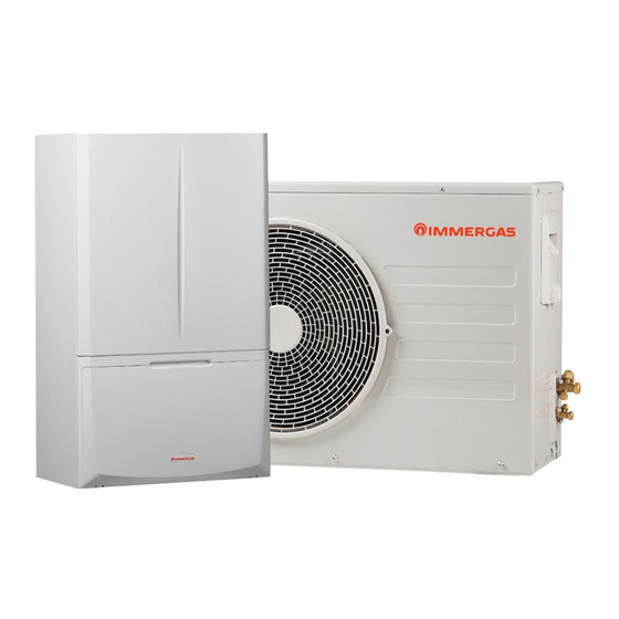
- Page 1 MAGIS PRO Instructions and recommendations Installer 4 - 6 - 9 V2 User Maintenance technician...
-
Page 3: Table Of Contents
INDEX Dear Customer .................. 4 Instructions for maintenance and initial check ... 45 Safety symbols used ................6 General recommendations ..........45 Personal protective equipment ............6 Initial check ................45 Yearly appliance check and maintenance ......46 Installing the indoor unit ..........7 Coil maintenance .............. -
Page 4: Dear Customer
Dear Customer Congratulations for having chosen a top-quality Immergas product, able to assure well-being and safety for a long period of time. As an Im- mergas customer you can also count on a Qualified Authorised After-Sales Technical Assistance Centre, prepared and updated to guarantee constant efficiency of your appliance. - Page 5 Law. • Improper installation or assembly of the Immergas device and/or components, accessories, kits and devices can cause unex- pected problems for people, animals and objects. Read the instructions provided with the product carefully to ensure proper installation.
-
Page 6: Safety Symbols Used
SAFETY SYMBOLS USED GENERIC HAZARD Strictly follow all of the indications next to the pictogram. Failure to follow the indications can generate hazard situations resulting in possible harm to the health of the operator and user in general, and/or property damage. ELECTRICAL HAZARD Strictly follow all of the indications next to the pictogram. -
Page 7: Installing The Indoor Unit
The place of installation of the appliance and relative Immergas accessories must have suitable features (tech- nical and structural), such as to allow for (always in safe, efficient and comfortable conditions):... - Page 8 Installation standards Only a professionally enabled company is authorised to This indoor unit can be installed outdoors in a partially install Immergas appliances. protected area. A partially protected area is one in which the indoor unit Check the environmental operating conditions of all is not exposed to the direct action of the weather (rain, parts relevant to installation, referring to this booklet.
- Page 9 Domus Container. Pay attention not to generate sparks as “Anti-Legionella” heat treatment of the Immergas stor- follows: age tank (function enabled when the system is provided – Do not remove the fuses while the unit with temperature control).
-
Page 10: Main Dimensions
MAIN DIMENSIONS Key (Fig. 2): - Electrical connection - System filling - Storage tank unit return MU - Storage tank unit flow - System return - System flow - Chiller line - liquid phase - Chiller line - gaseous phase Height Width Depth... -
Page 11: Antifreeze Protection
- The materials used for the central heating circuit of Immergas indoor unit resist ethylene and propylene glycol based anti- freeze liquids (if the mixtures are prepared perfectly). -
Page 12: Indoor Unit Connection Unit
INDOOR UNIT CONNECTION UNIT HYDRAULIC CONNECTION - The hydraulic connection unit is supplied as per standard with In order not to void the warranty, before making indoor Magis Pro V2. Make the hydraulic connection as shown below, unit connections, carefully clean the heating system making sure to protect the system flow and return pipes with (pipes, radiators, etc.) with special pickling or de-scaling their supplied insulating sheaths. -
Page 13: Connecting The Chiller Line
In order to meet the system requirements established by EN 1717 in terms of pollution of drinking water, we recommend installing the IMMERGAS anti-backflow kit to be used upstream of the cold water inlet connection of the indoor unit. We also recommend... -
Page 14: Electrical Connection
ELECTRICAL CONNECTION To protect from possible dispersions of The internal unit has an IPX4D degree of protection; electrical DC voltage, it is necessary to provide a safety of the appliance is achieved only when it is properly con- type A differential safety device. nected to an efficient earthing system, as specified by current safe- ty standards. - Page 15 Vertical terminal block electrical connection diagram. A 3rd zone (mixed) can also be managed on the system by means The zone 3 dehumidifier, if any, will be managed by means of the of the configurable relay interface kit (optional). configurable relay interface kit, which the zone 3 mixer will also In this case, the zone 3 pump must be connected according to dia- be connected to.
- Page 16 Horizontal terminal block electrical connection diagram.
-
Page 17: Room Chrono-Thermostats (Optional)
40-1 / 41 terminals, eliminating the X40-1 jumper All Immergas chrono-thermostats are connected with 2 wires for zone 1 and 40-2 / 41 for zone 2 and 40-3 / 42 for zone 3. only. -
Page 18: Modbus Temperature And Humidity Room Probes (Optional)
1.11 MODBUS TEMPERATURE AND Connect the appliance as shown (Fig. 8); HUMIDITY ROOM PROBES (OPTIONAL) The temperature and humidity probe is used to detect room hu- midity and to calculate the relative dew point by regulating the flow temperature during the cooling phase. DIP-Switch configuration table DIP 1-5 DIP 6-7... -
Page 19: Remote Zone Control (Optional)
1.12 REMOTE ZONE CONTROL (OPTIONAL) 1.15 EXTERNAL TEMPERATURE PROBE (OPTIONAL) This remote device is used to adjust the setpoints and to view the main information of the zone where it was configured. In the outdoor unit there is an external probe as standard. Connect as shown (Fig. -
Page 20: Temperature Control Setting
1.16 TEMPERATURE CONTROL SETTING The curves (Fig. 11, 12, 13, 14, 15, 16) show the default settings in the various operating modes available both with external probe By setting the parameters in the “Heat regulation” menu, you can and without. adjust how the system operates. -
Page 21: System Filling
Key (Fig. 11,13,12,14,15,16) 1.17 SYSTEM FILLING - Central Heating Set Once the indoor unit is connected, fill the system using the filling - Cooling Set cock (Fig. 21). - “Temperature control” menu parameter The indoor unit has one incorporated automatic vent valve locat- - External temperature ed on the circulator and another on the central heating manifold. -
Page 22: Operating Limits
1.18 OPERATING LIMITS 1.19 INDOOR UNIT START-UP (IGNITION) The system was designed to work in a specific range of tempera- After having installed the chiller lines on the outdoor unit, to tures and at a specific maximum flow temperature. The graphic commission the heat pump (the operations listed below must only (Fig. -
Page 23: Circulation Pump
1.20 CIRCULATION PUMP If the pump detects an alarm, the LED switches from green to red; this can mean one of the following failures: The appliance is supplied with a variable speed circulator pump, - low supply voltage; which operates at the speed set in the “A04” parameter (which can - rotor seized;... -
Page 24: Kits Available On Request
1.21 KITS AVAILABLE ON REQUEST - 3 kW heating system integrated resistance kit. Should it be nec- essary, you can install an electrical resistance to supplement the central heating system; this resistance can be installed directly inside the indoor unit. - 2 zone kit (1 direct and 1 mixed). -
Page 25: Main Components
1.22 MAIN COMPONENTS Key (Fig. 21): - Air vent valve - Return probe - Liquid phase detection probe - 3-way valve (motorised) - Domestic hot water inlet cock - System expansion vessel - System draining cock - System filling cock - Flow probe - System shut-off cock - Relay (optional) -
Page 26: Instructions For Use And Maintenance
INSTRUCTIONS FOR USE AND Do not climb on the appliance, do not use MAINTENANCE the appliance as a support base. GENERAL RECOMMENDATIONS Only use the user interface devices listed in this section Never expose the indoor unit to direct va- of the booklet. - Page 27 Water at a temperature of more than 50 °C can cause serious burns. Always check the water temperature be- fore any use. The temperatures indicated by the display have a toler- ance of +/- 3°C due to environmental conditions that cannot be blamed on the indoor unit.
-
Page 28: Cleaning And Maintenance
2.3 CONTROL PANEL Key (Fig. 22): - Connection to other Immergas units - Central heating room mode function active - Operating mode (winter - air conditioning - summer - stand- - Temperature indicator, indoor unit info and error codes... -
Page 29: System Use
SYSTEM USE Winter In this mode, the system works both to product domestic how wa- Before ignition, make sure the system is full of water, ter and room central heating. checking that the pressure gauge needle (6) points to a The temperature of the DHW is always regulated via buttons (4), value between 1 and 1.2 bar and make sure that the the central heating temperature is regulated via buttons (5) and... - Page 30 “Stand-by” Mode Operation with external probe Press button (1) repeatedly until the symbol appears. The sys- The system is set up to use the outdoor unit external probe or an tem remains off from this moment, though the antifreeze, pump optional external probe.
-
Page 31: Fault And Anomaly Signals
2.5 FAULT AND ANOMALY SIGNALS The indoor unit signals any anomalies by flashing a code on the display (14) according to the following table. Error Anomaly signalled Cause Indoor unit status / Solution Code Delivery probe fault The board detects an anomaly on the flow NTC probe. The system does not start (1). - Page 32 Error Anomaly signalled Cause Indoor unit status / Solution Code Safety thermostat During normal operation, if an anomaly causes excessive The unit does not meet the zone E 34 intervention Mixed overheating of the flow temperature in the mixed zone 2, central heating requirement.
- Page 33 Error Anomaly signalled Cause Indoor unit status / Solution Code In addition to the humidity, the dew Zone 2 humidity point is not calculated for the zone E 130 Anomaly on the zone 2 humidity probe. probe anomaly either (1). Zone humidity cannot be checked.
- Page 34 Error Anomaly signalled Cause Indoor unit status / Solution Code Liquid phase probe Check that the cooling circuit is E 195 low temperature Too low temperature is detected in the liquid phase working properly (1). anomaly Flow high An excessively high temperature is detected on the heat E 196 Check the hydraulic circuit (1).
- Page 35 List of outdoor unit anomalies On the interface board, the error is displayed with an “E” + error If the outdoor unit is faulty, the error code is signalled on the con- code, showing a sequence of two digits. trol panel (Fig. 22) and on the interface board (see paragraph "In- For example: terface board - 7-segment display").
- Page 36 Error Code Anomaly signalled Indoor unit status / Solution Check the position of the sensor. Check the relative wiring Compressor sensor error (overload protection A320 sensor) Replace the sensor Check the chiller cycle. A403 Freezing detection (during cooling operation) Check the temperatures of the plate heat exchanger Check the chiller cycle.
- Page 37 Error Code Anomaly signalled Indoor unit status / Solution Check the compressor connections. Check the resistances between the different phases of the compres- A467 Compressor rotation error sor. Check the main board. A468 Current sensor error (inverter) Check the power connector of the inverter board. A469 Voltage sensor error of DC circuit (inverter) Check the connectors RY21 and R200 of the inverter board.
- Page 38 Error Code Anomaly signalled Indoor unit status / Solution Indoor unit error A903 Not used Check indoor unit Indoor unit error A904 Not used Check indoor unit Indoor unit error A906 Not used Check indoor unit Indoor unit error A911 Not used Check indoor unit Indoor unit error...
-
Page 39: Parameters And Information Menu
PARAMETERS AND INFORMATION To scroll through the menu items and to edit the values, use the MENU heating temperature control buttons (5). Pressing the “OK” but- ton (1) confirms the parameter, while pressing the “ESC” button Pressing the “MENU” button (2), the display cyclically shows the (3) goes back to the previous menu or exits. - Page 40 MP - MCI - MCP Plus V2) D 62 Communication with interface board OFF - ON D 63 Communication with other Immergas devices OFF - ON D 71 External unit operating frequency 0 ÷ 150 Hz D 72 Compressor temperature -20 ÷...
- Page 41 Parameter ID Description Range D131 Outdoor unit inverter board memory version (4/4) 1 ÷ 99 D132 Outdoor unit inverter board firmware version (1/4) 1 ÷ 99 D133 Outdoor unit inverter board firmware version (2/4) 1 ÷ 99 D134 Outdoor unit inverter board firmware version (3/4) 1 ÷...
- Page 42 User Menu. Parameter Customised Description Range Default value U 01 Zone 2 heating flow set point in case of no thermal regulation (“R 01” = OFF). 20 ÷ 65 °C U 02 Zone 2 cooling flow set point in case of no thermal regulation (“R 01” = OFF) 5 ÷...
- Page 43 Parameter Customised Description Range Default value U 21 Hour setting (internal clock) 0 - 23 hours U 22 Minutes setting (internal clock) 0 - 59 minutes Mo-Tu-We- U 23 Day of the week Th-Fr-Sa-Su U 24 Current day 1 ÷ 31 U 25 Current month 1 ÷...
-
Page 44: Indoor Unit Shutdown
1. Periodically check the system water pressure (the indoor system using anti-freeze liquid and installing the Immergas Anti- unit’s pressure gauge hand must indicate a value between 1 freeze Kit in the indoor unit. -
Page 45: Instructions For Maintenance And Initial Check
1-1.2 bar; to the above, only use original Immergas spare parts - make sure the chiller circuit has been filled according to what is when replacing components. -
Page 46: Yearly Appliance Check And Maintenance
YEARLY APPLIANCE CHECK AND COIL MAINTENANCE MAINTENANCE We recommend regularly inspecting the finned air coils The following checks and maintenance should be per- to check the level of fouling. formed once a year to ensure operation, safety and effi- ciency of the appliance over time. This depends on the environment where the unit is installed. -
Page 47: Hydraulic Diagram
HYDRAULIC DIAGRAM Key (Fig. 27): - Three-way valve (motorised) - System filling valve - System shut-off cock - System with filter cut-off fitting - 3 bar Safety valve assembly - System shut-off cock - Pump - Air vent valve - Chiller line - liquid phase - System draining valve - Chiller line - gaseous phase - Liquid phase detection probe... -
Page 48: Wiring Diagram
WIRING DIAGRAM Key (Fig. 28): - Two-relay board (optional) - Interface board - P.C.B. - External unit - Low voltage electrical connection clamps (230 Vac) - Dominus (optional) - Very low safety voltage electrical connection clamps A32-1 - Zone 1 remote control (optional) - P.C.B. - Page 51 Key (Fig. 31): - Heat pump flow probe - Heat pump return probe - System flow meter - DHW priority 3-way valve...
- Page 52 Key (Fig. 32): Colour code key (Fig. 32): - P.C.B. - Black - Three-relay board (optional) - Blue - Brown - Green - Grey - Yellow/Green - Orange - Viola - Pink - Red - White - Yellow W/BK - White/Black...
- Page 53 Key (Fig. 33): Colour code key (Fig. 33): - P.C.B. - Black A16-1 - Zone 1 dehumidifier (optional) - Blue A16-2 - Zone 2 dehumidifier (optional) - Brown - Two-relay board (optional) - Green - Grey - Yellow/Green - Orange - Viola - Pink - Red...
- Page 54 P.C.B. Key (Fig. 34): - F 3.15A H250V fuse Interface board - setting switch Key (Fig. 35): - Factory setting: do not change...
- Page 55 Interface board - indicator LED Key (Fig. 36): Red LED flashing = Communication between interface board and P.C.B. valid Green LED flashing = Communication between interface board and outdoor unit valid Yellow LED = Not Used Interface board - 7-segment display During normal operation, the display shows “A0”...
-
Page 56: System Filter
SYSTEM FILTER Red pump LED. There can be three possible causes for this anomaly: The indoor unit has a filter on the system return fitting to keep the - Low power supply voltage. About 1-2 seconds after the voltage system in good operating conditions. drops below 145Vac, the LED switches from green to red and the Periodically and when necessary, the filter can be cleaned as de- pump stops. -
Page 57: Programming
P.C.B. PROGRAMMING Once you have accessed programming, you can scroll through the parameters in the “System” menu. The water heater is set up for possible programming of several op- Using the “central heating regulation” button, select the parame- eration parameters. By modifying these parameters as described ter and edit the value. - Page 58 1 ÷ 247 cation address unit and the outdoor unit OFF = BMS communication protocol on 485; use if BMS communi- connected to optional Immergas devices. OFF - 485 A 22 cation setting 485 = Do not use - UC...
- Page 59 Value Parameter Description Range Default Parameter value SE = Humidity temp. Sensor ST = Humidistat Zone 2 room A 32 Defines the temperature control in zone 2 RP - Remote thermostat panel RPH = Remote panel with humidis- SE = Humidity temp.
- Page 60 Value Parameter Description Range Default Parameter value The indoor unit is set-up for functioning with the relay P.C.B. (optional), which can be configured 0 = Off Relay 1 1 = DHW recirculation P 03 0 ÷ 4 (optional) 2 =General alarm 3 = Central heating / cooling mode active 4 = Puffer mode active 5 = Dehumidifier zone 3...
- Page 61 Value Parameter Description Range Default Parameter value Anti-Legionella P 15 Enable running of anti-Legionella function OFF - ON function enable Anti-Legionella P 16 Allows to set when anti-Legionella function starts 0 - 23 start time Allows to set the weekday on which to activate the anti-Le- Anti-Legionella P 17 gionella function.
- Page 62 Value Parameter Description Range Default Parameter value Establishes the unit ignition and switch-off mode in DHW mode. D.H.W. T 02 It is enabled when the water in the storage tank goes below 0 ÷ 20 °C thermostat the DHW set value and is disabled when the temperature exceeds the DHW set value.
- Page 63 Heat regulation menu. Value Parameter Description Range Default Parameter value Defines if and which external probe is used to manage the system. R 01 External probe OFF = no external probe used OFF - OU - IU OU = external probe on outdoor unit IU = optional external probe connected to the indoor unit Outdoor temperature for...
- Page 64 Value Parameter Description Range Default Parameter value Outdoor temperature for Establishes the minimum outdoor temperature at which to R 11 Zone 1 20 ÷ 40 have the maximum flow temperature in zone 1 cooling mode maximum cooling flow Zone 1 Defines the minimum flow temperature in zone 1 room R 12 minimum...
- Page 65 Value Parameter Description Range Default Parameter value Outdoor temperature for Zone 3 low Establishes the outdoor temperature at which to have the R 25 20 ÷ 40 temperature maximum flow temperature of zone 3 zone min cooling flow Outdoor temperature for Zone 3 low Establishes the outdoor temperature at which to have the R 26...
- Page 66 Integration menu. Value Parameter Description Range Default Parameter value DHW integra- Allows you to enable an alternative power source (AL) to I 01 OFF - AL tion enabling integrate domestic hot water heating System Using this function, you can enable an alternative (AL) or I 02 integration simultaneous (CO) power source to integrate heating system...
- Page 67 Maintenance menu. Accessing this menu, the unit goes into stand-by. By selecting every single parameter, you can activate a specific function for each load. Value Parameter Description Range Default Parameter value System M 02 circulator pump Establishes the system circulator pump speed 0 - 100% speed DHW-CH-...
-
Page 68: Pump Anti-Block Function
3.10 PUMP ANTI-BLOCK FUNCTION 3.16 ANTI-LEGIONELLA FUNCTION The indoor unit has a function that starts the pump at least once The indoor unit is equipped with a function to perform a thermal every 24 hours for the duration of 30 seconds in order to reduce the shock on the storage tank. -
Page 69: Screed Heater Function
3.19 SCREED HEATER FUNCTION In case of failure, the function is suspended and will resume when normal operating conditions are reset from the point where it was The indoor unit is equipped with a function to perform the ther- interrupted. mal shock on new radiant panel systems, as required by the appli- In case of power failure, the function is suspended. -
Page 70: Outdoor Unit Testmode Function
3.21 OUTDOOR UNIT TESTMODE FUNCTION 3.25 SYSTEM SETPOINT CORRECTION FUNCTION When test mode is used (see outdoor unit instruction booklet), the indoor unit must be set in a mode other than “Stand-by”. In the presence of hydraulic disconnections on the system which The alarm E183 is triggered during the test, meaning “Test mode”... -
Page 71: Casing Removal
3.28 CASING REMOVAL Front panel (Fig. 41) - Open the protection door (e1) pulling it towards you. To facilitate indoor unit maintenance the casing can be complete- - Remove the cover caps (c) and loosen screws (d). ly removed as follows: - Pull the front panel (e) towards you and release it from its lower seat. - Page 72 Control panel (Fig. 43) Sides (Fig. 45) - Press the hooks on the side of the control panel (i). - Unscrew the side (k) fastening screws (l). - Tilt the control panel (i) towards you. - Remove the sides by extracting them from their rear seat (Ref. The control panel (i) can rotate until the support cord (j) is com- pletely extended.
-
Page 73: Technical Data
TECHNICAL DATA TECHNICAL DATA TABLE The data below refer to the pairing between indoor unit and outdoor unit. MAGIS PRO 4 V2 MAGIS PRO 6 V2 MAGIS PRO 9 V2 Nominal data for low temperature applications (A7/W35) * Nominal central heating output 4,40 6,00 9,00... - Page 74 Indoor unit data MAGIS PRO 4 V2 MAGIS PRO 6 V2 MAGIS PRO 9 V2 Dimensions (Width x Height x Depth) 440x760x250 Maximum heating temperature °C Adjustable central heating temperature (max operating °C 20-65 field) Cooling adjustable temperature (max. operating field) °C 5-25 Domestic hot water adjustable temperature...
-
Page 75: Magis Pro 4 V2 Product Fiche (In Compliance With Regulation 811/2013)
MAGIS PRO 4 V2 PRODUCT FICHE (IN COMPLIANCE WITH REGULATION 811/2013) For proper installation of the appliance refer to chapter 1 of this booklet (for the installer) and current installation regulations. For proper maintenance refer to chapter 3 of this booklet (for the maintenance technician) and adhere to the frequencies and meth- ods set out herein. - Page 76 For mixed central heating appliances with a heat pump Stated load profile Water central heating energy efficiency η Daily electrical power consumption kWh Daily fuel consumption elec fuel Annual energy consumption kWh Annual fuel consumption Contact information Immergas S.p.A. via Cisa Ligure n.95...
-
Page 77: Magis Pro 6 V2 Product Fi Che (In Compliance With Regulation 811/2013)
4.3 MAGIS PRO 6 V2 PRODUCT FICHE (IN COMPLIANCE WITH REGULATION 811/2013) For proper installation of the appliance refer to chapter 1 of this booklet (for the installer) and current installation regulations. For proper maintenance refer to chapter 3 of this booklet (for the maintenance technician) and adhere to the frequencies and meth- ods set out herein. - Page 78 For mixed central heating appliances with a heat pump Stated load profile Water central heating energy efficiency η Daily electrical power consumption kWh Daily fuel consumption elec fuel Annual energy consumption kWh Annual fuel consumption Contact information Immergas S.p.A. via Cisa Ligure n.95...
-
Page 79: Magis Pro 9 V2 Product Fi Che (In Compliance With Regulation 811/2013)
MAGIS PRO 9 V2 PRODUCT FICHE (IN COMPLIANCE WITH REGULATION 811/2013) For proper installation of the appliance refer to chapter 1 of this booklet (for the installer) and current installation regulations. For proper maintenance refer to chapter 3 of this booklet (for the maintenance technician) and adhere to the frequencies and meth- ods set out herein. - Page 80 For mixed central heating appliances with a heat pump Stated load profile Water central heating energy efficiency η Daily electrical power consumption kWh Daily fuel consumption elec fuel Annual energy consumption kWh Annual fuel consumption Contact information Immergas S.p.A. via Cisa Ligure n.95...
-
Page 81: Parameters For Filling In The Package Fiche
4.5 PARAMETERS FOR FILLING IN THE The remaining values must be obtained from the technical data PACKAGE FICHE sheets of the products used to make up the assembly (e.g. solar de- vices, integration hydronic module, temperature controllers). Should you wish to install an assembly starting from the Magis Use board (Fig. - Page 82 Parameters to fill in the low temperature package fiche (30/35) Parameters to fill in the average temperature package fiche (47/55) Magis PRO 4 V2 Magis PRO 4 V2 Parameter Colder zones Average zones Hotter zones Parameter Colder zones Average zones Hotter zones "I"...
- Page 83 Room central heating system package fiche. ____ Temperature control Class I = 1 %, Class II = 2 %, Class III = 1.5 %, Class IV = 2 %, From temperature Class V = 3 %, Class VI = 4 %, control board Class VII = 3.5 %, Class VIII = 5 % Supplementary boiler...
- Page 88 This instruction booklet is made of ecological paper. immergas.com Immergas S.p.A. 42041 Brescello (RE) - Italy Tel. 0522.689011 Fax 0522.680617...