Table of Contents
Advertisement
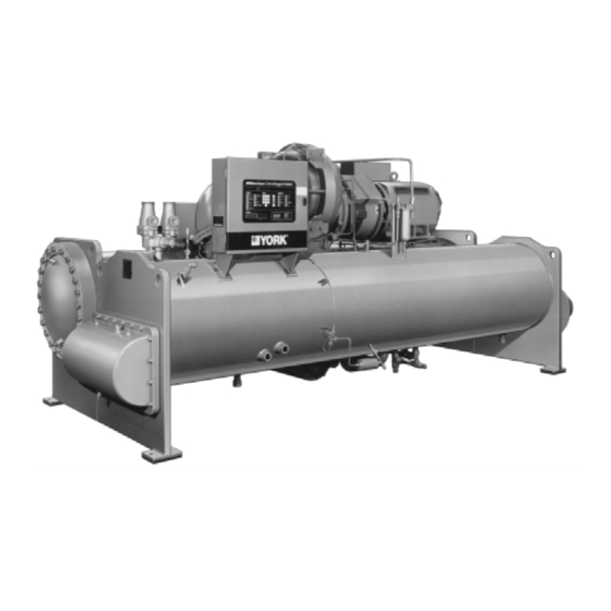
OPERATING & MAINTENANCE
MODEL YK M3 M3 G4 THRU YK S6 S4 J2 (STYLE C)
MODEL YK LB LB G4 THRU YK SE SC J4 (STYLE C)
WITH MICROCOMPUTER CONTROL CENTER
PART #371-01200-010, 371-01200-011 & 371-01200-015
FOR ELECTRO-MECHANICAL STARTER,
Solid State Starter & VARIABLE SPEED DRIVE
SYSTEM CONTAINS REFRIGERANT UNDER PRESSURE.
SERIOUS INJURY COULD RESULT IF PROPER PROCEDURES ARE NOT
FOLLOWED WHEN SERVICING SYSTEM. ALL SERVICE WORK SHALL
BE PERFORMED BY A QUALIFIED SERVICE TECHNICIAN IN ACCOR-
DANCE WITH YORK INSTALLATION/OPERATION MANUAL.
CENTRIFUGAL LIQUID CHILLERS
Supersedes: Nothing
R-22 (COOLING ONLY)
R-134a (COOLING ONLY)
W W W W W ARNING
ARNING
ARNING
ARNING
ARNING
MILLENNIUM
TM
Form 160.49-O2 (1296)
27385A
Advertisement
Table of Contents

Related Manuals for York Millennium YK M3 M3 G4 THRU YK S6 S4 J2, YK LB LB G4 THRU YK SE SC J4


Summary of Contents for York Millennium YK M3 M3 G4 THRU YK S6 S4 J2, YK LB LB G4 THRU YK SE SC J4
- Page 1 SYSTEM CONTAINS REFRIGERANT UNDER PRESSURE. SERIOUS INJURY COULD RESULT IF PROPER PROCEDURES ARE NOT FOLLOWED WHEN SERVICING SYSTEM. ALL SERVICE WORK SHALL BE PERFORMED BY A QUALIFIED SERVICE TECHNICIAN IN ACCOR- DANCE WITH YORK INSTALLATION/OPERATION MANUAL. MILLENNIUM CENTRIFUGAL LIQUID CHILLERS Supersedes: Nothing...
-
Page 2: Table Of Contents
System Component Description ... 37 Operational Maintenance ... 42 Trouble Shooting ... 44 Maintenance ... 49 Preventive Maintenance ... 58 UCTIONS UCTIONS UCTIONS UCTIONS DESCRIPTION Page FORM NO. 160.46-OM3.1 160.00-O1 160.49-N5 160.49-N7 160.49-PW7 160.49-PW10 160.49-PW13 160.49-PW8 160.49-PW11 160.49-PW14 160.49-PW8 160.49-PW9 160.49-PW12 160.49-PW15 YORK INTERNATIONAL... - Page 3 PB, PC, QB, QC, RB, RC, SB, SC COOLER CODE LB, LC, MB, MC, NB, NC, PB, PC, PD, PE, QB, QC, QD, QE, RB, RC, RD, RE, SD, SE MODEL YORK INTERNATIONAL NOMENCLATURE DESIGN LEVEL (C) POWER SUPPLY – for 60 HZ...
-
Page 4: Fundamentals Of Operation
COOLER FIG. 1 – MODEL YK MILLENNIUM CHILLER SYSTEM OPERATION DESCRIPTION (See Fig. 2) The YORK Model YK Millennium Chiller is commonly applied to large air conditioning systems, but may be used on other applications. The chiller consists of an... - Page 5 SUB-COOLER FLOW CONTROL ORIFICE FIG. 2 – REFRIGERANT FLOW-THRU CHILLER YORK INTERNATIONAL design conditions. However, most systems will be called upon to deliver full load capacity for only a relatively small part of the time the unit is in operation.
-
Page 6: Section 2 – Microcomputer Control Center
Responsibility for assuring the satisfactory operation of other equipment included in the same power source as the YORK equipment rests solely with the user. YORK disclaims any liability resulting from any interference or for the correction thereof. SECTION 2... - Page 7 It controls the leaving chilled water tem- perature via pre-rotation vane control and has the ability to limit motor current via control of the pre-rotation vanes. Further, it is compatible with YORK Solid State Starter (optional), Variable Speed Drive (optional), and electro- mechanical starter applications.
- Page 8 (PSIG) except oil pressure which is displayed in pounds per sq. inch differ- ential (PSID). If the “English/Metric” jumper is not installed, all temperatures are displayed in degrees Centigrade (°C) and all pressures are displayed in Kilo-Pascals (kPa). RUN, STOP/RESET YORK INTERNATIONAL...
- Page 9 To Display SSS MOTOR CURRENT / VOLTS: (Solid State Starter Applications Only) If chiller is equipped with a YORK Solid State Starter, use SSS MOTOR CURRENT / VOLTS key to dis- play 3-phase compressor motor current and 3-phase Solid State Starter input line voltage.
- Page 10 (FLA). If not programmed, the default value is 100%. (See “Programming System Setpoints”, page 15.) If chiller is equipped with a YORK Solid State Starter, the system FLA is also displayed. This value is pro- grammed by the factory and should never be changed.
- Page 11 46°F to 56°F (46 + 10 = 56). If not programmed, the default value for this parameter is 20°F. YORK INTERNATIONAL For additional information on remote LCWT reset, refer to Form 160.49-PW13.
- Page 12 REMOTE mode is that which has been pro- grammed by the Energy Management System via the remote current limit setpoint input. If chiller is equipped with a YORK Solid State Starter, the message is: CURRENT LIMIT = XXX % FLA; *MTR CUR = 000 FLA NOTE: On Solid State Starter applications, this value is programmed at the YORK factory.
- Page 13 REMOTE RESET TEMP RANGE = 10°F – or – REMOTE RESET TEMP RANGE = 20°F To Display DATA LOGGER setpoints: Refer to YORK, Form 160.49-N7 for operation of this key. YORK INTERNATIONAL To Display UNDERVOLTAGE setpoints: (Solid State Starter Applications Only) Press SSS MOTOR CURRENT/VOLTS key in PRO- GRAM mode to display the selected voltage range.
- Page 14 PROGRAM mode. ACCESS TO PROGRAM MODE DISABLED The Control Center will automatically return to LO- CAL, REMOTE or SERVICE mode ..whichever is displayed. was last selected. LD00954 message will re- is displayed. YORK INTERNATIONAL...
- Page 15 CURRENT LIMIT = XXX% FLA; MTR CUR = _ _ _ FLA 2. Use ENTRY keys to enter desired value. NOTE: Motor Current FLA value is entered by YORK factory and checked at system start-up. It cannot be changed without special access code.
- Page 16 “0”. For example, 02/04/88. 7. Press and release ENTER key. PROGRAM MODE, SELECT SETPOINT message is displayed. FIG. 8 – KEYPAD – PROGRAMMING “PULL DOWN DEMAND” SETPOINT FIG. 9 – KEYPAD – PROGRAMMING “CLOCK” SETPOINT YORK INTERNATIONAL LD00957 LD00958...
- Page 17 If you press the 0 Entry key, Tuesday through Fri- day can be programmed with different start and stop times. YORK INTERNATIONAL 6. Use the ADVANCE DAY / SCROLL key with proce- dure in Step 2. To enter start and stop times for remainder of the week plus a holiday schedule if required.
- Page 18 To Enter DATA LOGGER Setpoint: Refer to Form 160.49-N7 for operation of this key. will appear FIG. 11 – KEYPAD – PROGRAMMING “HOLIDAY” SETPOINT FIG. 12 – KEYPAD – PROGRAMMING “REMOTE RESET” TEMP RANGE LD00961 LD00962 YORK INTERNATIONAL...
- Page 19 CLOSE, HOLD, or AUTO (if temperature error requires it) keys are pressed and released. HOLD – Press and release this key to hold the pre- rotation vanes in their present position. If the chiller is YORK INTERNATIONAL SERVICE KEYS running, SYSTEM RUN – VANES HOLDING If chiller is not running, SYS READY TO START –...
- Page 20 HOP = XX.X PSIG; LOP = XX.X PSIG pressure (LOP) as measured at the oil sump and the high oil pressure (HOP) as measured at the compres- sor bearing input. YORK INTERNATIONAL – Displays – This is the – This is the low oil...
-
Page 21: Operating Modes
PRESSOR switch when in the REMOTE mode. To determine which operating mode the Control Center is presently in, simply press the MODE key. YORK INTERNATIONAL To hold any of the above messages, press the DISPLAY DATA key, then press the DISPLAY HOLD key. The –... -
Page 22: Display Messages
50% and the FLA of the chiller equal to 200A, the current limit circuit would perform as follows: (100%) (50% x FLA) = Vanes inhibited from open- ing further. (104%) (50% x FLA) = Vanes driven toward close position. is displayed. is displayed. YORK INTERNATIONAL... - Page 23 Displayed when the chiller is not running and the op- erator has pressed the vanes CLOSE key on the key- pad. YORK INTERNATIONAL SYS READY TO START – VANES HOLDING Displayed when the chiller is running and the operator has pressed the vanes HOLD key on the keypad.
- Page 24 MON XX:XX AM – POWER FAILURE – AUTOSTART The chiller is shut down because there has been a power interruption or failure. The chiller will automati- cally restart when power is restored. This message Cause of Shutdown Type of Restart YORK INTERNATIONAL...
- Page 25 The chiller will restart upon application of a separate start signal from the remote device. This message will only be displayed YORK INTERNATIONAL when Control Center is in REMOTE mode. ANTI-RECYCLE, XX MIN LEFT The chiller may not restart more frequently than every 30 minutes.
- Page 26 The chiller is shut down because a current module (CM-2 Electro-Mechanical starter application), or the YORK Solid State Starter or the Variable Speed Drive initiated a shutdown. To restart system, reset the ex- ternal device that caused the shutdown. The chiller will then automatically restart.
- Page 27 This is the compressor pre-lube period. The duration of this period is controlled by the “Prerun” (JP6) wire YORK INTERNATIONAL jumper on the Micro Board as follows: FUNCTION 50 Sec. Oil Pump Prerun 180 Sec.
- Page 28 This special reset procedure is detailed in YORK Service manual, Form 160.49-M3. Failure to perform the visual inspection prior to restarting the chiller could result in severe compressor damage!!! DAY –...
- Page 29 The chiller cannot be restarted until the “Special Reset Proce- dure” in YORK Service manual, Form 160.49-M3 is per- formed by a qualified service technician. MON XX:XX AM – HIGH SPEED DRAIN TEMP The chiller has shut down because the “Proximity/Tem-...
-
Page 30: Section 3 – System Operating Procedures
LCWT = 45°F % Current Limit = 100% FLA Pulldown Demand = None Clock = Sun 12:00 A.M. Daily Schedule = None Holiday = None Remote Reset Temp. Range = 20°F Data Logger = No operation on (Solid YORK INTERNATIONAL... - Page 31 YORK INTERNATIONAL The high and low oil pressure transducers (OP) and the oil temperature sensor (RT3) will sense any malfunction in the lubrication system and ac- tivate one of the following display messages: DAY 10:30 AM –...
- Page 32 10 minutes, the LWT cutout is 36°F for 10 minutes. Condenser Water Temperature Control The YORK Millennium chiller is designed to use less power by taking advantage of lower than design tem- peratures that are naturally produced by cooling tow- ers throughout the operating year.
- Page 33 An optional status printer is available for this purpose or Fig. 16 shows a log sheet used by YORK Personnel for recording test data on chiller systems. It is avail- able from the factory in pads of 50 sheets each under Form 160.44-F6 and may be obtained through the nearest...
- Page 34 YORK office. Automatic data logging is possible by connecting the optional printer and programming the DATA LOGGER function; refer to Form 160.49-N7. An accurate record of readings serves as a valuable reference for operating the system. Readings taken when a system is newly installed will establish normal conditions with which to compare later readings.
- Page 35 YORK District Office. Failure to report constant troubles could damage the unit and increase the cost of repairs considerably.
- Page 36 UAL OIL PUMP key) until steady oil pressure is established. Then press and release the OIL PUMP key to stop operation of the oil pump. If the water systems were drained, fill the condenser water cir- cuit and chilled liquid circuit. YORK INTERNATIONAL...
-
Page 37: Section 4 – System Component Description
SYSTEM COMPONENTS DESCRIPTION MICROCOMPUTER CONTROL CENTER SUCTION DUAL RELIEF VALVES OIL PUMP STARTER OIL RESERVOIR/ PUMP FIG. 17 – SYSTEM COMPONENTS YORK INTERNATIONAL SECTION 4 DISCHARGE COMPRESSOR DEHYDRATOR SIGHT GLASSES FRONT VIEW DISCHARGE LINE FORM 160.49-O2 ADAPTER MOTOR SUPPORT & COVER... - Page 38 Oil is shipped in containers with the chiller. Refrigerant is shipped to the jobsite in cylinders at the time of installation. The services of a YORK factory-trained, field service representative are included to supervise the final leak testing, charging and the initial start-up and concur- rent operator instructions.
- Page 39 FORM 160.49-O2 LD00951 FIG. 18 – SCHEMATIC DRAWING – (YK) COMPRESSOR LUBRICATION SYSTEM YORK INTERNATIONAL...
- Page 40 30°F above condenser temperature. MOTOR DRIVELINE The compressor motor is an open-drip-proof, squirrel cage, induction type constructed to YORK design speci- fications. 60 hertz motors operate at 3570 rpm. 50 hertz motors operate at 2975 rpm. (For 60 hertz motors 1750 HP and smaller; and 50 hertz motors 1400 HP and smaller) .
- Page 41 (i.e., when a close pulse is applied to the vane motor, an open pulse is applied to the level YORK INTERNATIONAL control, etc.). When the VMS opens, if the refrigerant level is less than the level setpoint, a refrigerant level setpoint pulldown is initiated as described above.
-
Page 42: Section 5 – Operational Maintenance
3. Assemble the new filter-drier. 4. Open condenser stop valve and check dehydrator connections for refrigerant leaks. 5. Open all the dehydrator stop valves to allow the liquid refrigerant to flow through the dehydrator and condenser-gas through the eductor. LD00950 YORK INTERNATIONAL... - Page 43 The nominal oil charge for the compressor is 20 gal., type “F” for R-22 application or type “K” for R-134a application. New YORK Refrigeration oil must be used in the cen- trifugal compressor. Since oil absorbs moisture when exposed to the atmosphere, it should be kept tightly capped until used.
- Page 44 TABLE 1 – CAUSES OF NORMAL AND SAFETY SYSTEM SHUTDOWNS IN ACCORDANCE WITH THE MICROCOMPUTER CONTROL, CENTER DISPLAY SHUTDOWN CAUSE CONTROL CENTER DISPLAY DAY OF TIME OF CAUSE OF METHOD OF WEEK SHUTDOWN RESTART MON. 10:00 AM Low Water Autostart Temp.
- Page 45 MON. 10:00 AM Low Evap. Low Evap. Pressure Pressure Transducer (LEP) MON. 10:00 AM Low Evap. LEP external Pressure control (Brine Brine units only) MON. 10:00 AM Low Oil Low Oil Pressure Pressure Transducer (OP) MON. 10:00 AM High High Pressure Pressure Safety Control (HP)
- Page 46 TABLE 1 – CAUSES OF NORMAL AND SAFETY SYSTEM SHUTDOWNS IN ACCORDANCE WITH THE MICROCOMPUTER CONTROL, CENTER DISPLAY SHUTDOWN CAUSE CONTROL CENTER DISPLAY DAY OF TIME OF CAUSE OF METHOD OF WEEK SHUTDOWN RESTART MON. 10:00 AM Oil Pressure Transducer Error Vane Motor Autostart...
- Page 47 SHORT WHILE, THEN COMPRESSOR STOPS ON OIL PRESSURE CUTOUT Oil pressure normal, fluctuates then compressor stops on Oil Pressure Cutout. Display reading LOW OIL PRESSURE YORK INTERNATIONAL POSSIBLE CAUSE Air in condenser. Condenser tubes dirty or . Clean condenser tubes. Check water scaled conditioning.
- Page 48 Faulty oil pressure Replace oil pressure transducer. transducer Faulty wiring/connectors. Excessive end clearance Inspect and replace worn parts. pump. Other worn pump parts. Partially blocked oil supply Check oil inlet for blockage. inlet. REMEDY YORK INTERNATIONAL...
-
Page 49: Section 7 – Maintenance
R-22 mixed with dry nitrogen so that a ha- EVACUATION AND DEHYDRATION OF UNIT FIG. 21 – EVACUATION OF CHILLER YORK INTERNATIONAL SECTION 7 MAINTENANCE lide torch or electronic leak detector can be used to detect any leaks too small to be found by the soap test. - Page 50 8 hour period. 7. If the vacuum does not hold for 8 hours within the limits specified in Step 6 above, the leak must be found and repaired. BOILING TEMPERATURES WATER °F –11 –38 –50 –70 YORK INTERNATIONAL...
- Page 51 35°F or a pres- sure of 5 mm Hg. is reached. YORK INTERNATIONAL FIG. 22 – SATURATION CURVE When this point is reached, practically all of the air has been evacuated from the system, but there is still a small amount of moisture left.
-
Page 52: Refrigerant Charging
LBS. COOLER COND. 1,425 1,150 1,600 1,150 1,675 1,400 1,800 1,400 1,800 1,585 1,875 1,650 1,875 1,805 2,175 1,805 2,225 1,900 2,500 1,900 2,800 2,205 3,050 2,235 3,300 2,515 3,500 2,800 3,500 3,075 3,500 3,325 3,450 3,450 3,575 YORK INTERNATIONAL... - Page 53 (see Fig. 23); these readings are to be interpreted using the graph shown in Fig. 24. FIG. 23 – DIAGRAM, MEGGING MOTOR WINDINGS YORK INTERNATIONAL DISMANTLING AND REPAIRS MEGGING THE MOTOR 2. If readings fall below shaded area, remove external leads from motor and repeat test.
- Page 54 Minimum Insulation Resistance vs. Temperature (per IEEE Std 43) Open Motors MEGOHMS...
- Page 55 COMMERCIAL ACID CLEANING In many major cities, commercial organizations now offer a specialized service of acid cleaning coolers and condensers. If acid cleaning is required, YORK FORM 160.49-O2...
- Page 56 6. If any of the tube sheet joints are leaking, the leak should be indicated by the detector. If a tube sheet leak is suspected, its exact location may be found by using a soap solution. A continuous buildup of bubbles around a tube indicates a tube sheet leak. YORK INTERNATIONAL...
- Page 57 If aluminum particles are noticeable and the same conditions continue to stop the unit operation after a new filter element is installed, notify the nearest YORK office to request the presence of a YORK Service man. ELECTRICAL CONTROLS The operating points of the pressure and temperature cut outs are shown in the Wiring Diagrams.
-
Page 58: Section 8 – Preventive Maintenance
IMPORTANT – If a unit failure occurs due to improper maintenance during the war- ranty period; YORK will not be liable for costs incurred to return the system to satisfactory operation. In any operating system it is most important to provide a planned maintenance and inspection of its function- ing parts to keep it operating at its peak efficiency. - Page 59 2. It is important that the factory settings of controls (operation and safety) not be changed. If the set- tings are changed without YORK’s approval, the warranty will be jeopardized. 3. A 5-11 year life battery is part of the RTC-Real Time Clock.
- Page 60 P.O. Box 1592, York, Pennsylvania USA 17405-1592 Subject to change without notice. Printed in USA Copyright © by York International Corporation 1997 ALL RIGHTS RESERVED Form 160.49-O2 (1296) Supersedes: Nothing...