York R-410A Installation Manual
R-410a affinity series 2-5 ton
Hide thumbs
Also See for R-410A:
- Technical & service manual (386 pages) ,
- Technical manual (129 pages) ,
- Installation manual (36 pages)
Table of Contents
Advertisement
R-410A
AFFINITY SERIES
DEX024-048
DEY060
General . . . . . . . . . . . . . . . . . . . . . . . . . . . . . . . . . . . . . . . . . . 1
Installation . . . . . . . . . . . . . . . . . . . . . . . . . . . . . . . . . . . . . . . . 3
Limitations . . . . . . . . . . . . . . . . . . . . . . . . . . . . . . . . . . . . . . 3
Location. . . . . . . . . . . . . . . . . . . . . . . . . . . . . . . . . . . . . . . . 4
Rigging And Handling . . . . . . . . . . . . . . . . . . . . . . . . . . . . . 4
Ductwork . . . . . . . . . . . . . . . . . . . . . . . . . . . . . . . . . . . . . . . 7
Roof Curb . . . . . . . . . . . . . . . . . . . . . . . . . . . . . . . . . . . . . . 7
Filters . . . . . . . . . . . . . . . . . . . . . . . . . . . . . . . . . . . . . . . . . 7
Condensate Drain . . . . . . . . . . . . . . . . . . . . . . . . . . . . . . . . 7
Service Access . . . . . . . . . . . . . . . . . . . . . . . . . . . . . . . . . . 8
Thermostat . . . . . . . . . . . . . . . . . . . . . . . . . . . . . . . . . . . . . 8
Power And Control Wiring. . . . . . . . . . . . . . . . . . . . . . . . . . 8
1 Unit Limitations . . . . . . . . . . . . . . . . . . . . . . . . . . . . . . . . . 3
2 Unit Accessory Weights . . . . . . . . . . . . . . . . . . . . . . . . . . 5
3 Unit Dimensions Front . . . . . . . . . . . . . . . . . . . . . . . . . . . . 5
4 Unit Clearances . . . . . . . . . . . . . . . . . . . . . . . . . . . . . . . . . 5
5 Electrical Data . . . . . . . . . . . . . . . . . . . . . . . . . . . . . . . . . . 9
6 Physical Data . . . . . . . . . . . . . . . . . . . . . . . . . . . . . . . . . 10
7 Side Duct Application . . . . . . . . . . . . . . . . . . . . . . . . . . . 12
8 Bottom Duct Application . . . . . . . . . . . . . . . . . . . . . . . . . 13
9 Additional Static Resistance . . . . . . . . . . . . . . . . . . . . . . 14
10 Electric Heat Minimum Supply Air . . . . . . . . . . . . . . . . . . 15
11 Indoor Blower Specifications . . . . . . . . . . . . . . . . . . . . . . 15
1 Component Location . . . . . . . . . . . . . . . . . . . . . . . . . . . . 3
2 Unit 4 Point Load Weight . . . . . . . . . . . . . . . . . . . . . . . . . 4
3 Unit Dimensions . . . . . . . . . . . . . . . . . . . . . . . . . . . . . . . . 5
4 Dimensions Front and Bottom . . . . . . . . . . . . . . . . . . . . . 6
5 Dimensions Back and Bottom . . . . . . . . . . . . . . . . . . . . . 6
6 Roof Curb . . . . . . . . . . . . . . . . . . . . . . . . . . . . . . . . . . . . . 7
Thermostat . . . . . . . . . . . . . . . . . . . . . . . . . . . . . . . . . . . . 8
General
®
YORK
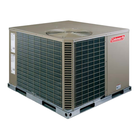
Affinity Models DEX and DEY units are factory
assembled cooling units designed for outdoor installation on a
roof top or a slab. Field-installed electric heater accessories are
available to provide supplemental electric heat combined with
electric cooling.
The units are completely assembled on rigid, removable base
rails. All piping, refrigerant charge, and electrical wiring is
factory installed and tested. The units require only electric
power and duct connections at the point of installation.
The electric heaters have nickel-chrome resistance wire
elements and utilize single point power connection.
Safety Considerations
This is a safety alert symbol
labels or in manuals, be alert to the potential for personal injury.
Understand and pay particular attention the signal words
DANGER, WARNING or CAUTION.
TABLE OF CONTENTS
LIST OF TABLES
LIST OF FIGURES
. When you see this symbol on
Compressors. . . . . . . . . . . . . . . . . . . . . . . . . . . . . . . . . . . 11
Phasing . . . . . . . . . . . . . . . . . . . . . . . . . . . . . . . . . . . . . . . 12
Airflow Performance . . . . . . . . . . . . . . . . . . . . . . . . . . . . . . . 12
Blower Speed Selection . . . . . . . . . . . . . . . . . . . . . . . . . . 17
Operation . . . . . . . . . . . . . . . . . . . . . . . . . . . . . . . . . . . . . . . 18
Cooling Sequence Of Operations . . . . . . . . . . . . . . . . . . . 18
Heating Sequence Of Operations . . . . . . . . . . . . . . . . . . . 18
Maintenance . . . . . . . . . . . . . . . . . . . . . . . . . . . . . . . . . . . . . 20
Normal Maintenance . . . . . . . . . . . . . . . . . . . . . . . . . . . . . 20
Troubleshooting . . . . . . . . . . . . . . . . . . . . . . . . . . . . . . . . . . 20
Typical Wiring Diagrams . . . . . . . . . . . . . . . . . . . . . . . . . . 21
12 Electric Heat Multipliers . . . . . . . . . . . . . . . . . . . . . . . . . 15
13 DEX024 Superheat Charging . . . . . . . . . . . . . . . . . . . . . 16
14 DEX030 Superheat Charging . . . . . . . . . . . . . . . . . . . . . 16
15 DEX036 Superheat Charging . . . . . . . . . . . . . . . . . . . . . 16
16 DEX042 Superheat Charging . . . . . . . . . . . . . . . . . . . . . 16
17 DEX048 Superheat Charging . . . . . . . . . . . . . . . . . . . . . 17
18 DEY060 Superheat Charging . . . . . . . . . . . . . . . . . . . . . 17
19 Delay Profile . . . . . . . . . . . . . . . . . . . . . . . . . . . . . . . . . . 18
20 Thermostat Signals (Single Phase Units) . . . . . . . . . . . . 19
21 Thermostat Signals (Three Phase Units) . . . . . . . . . . . . 19
Thermostat . . . . . . . . . . . . . . . . . . . . . . . . . . . . . . . . . . . . 9
9 Typical Field Power Wiring Diagram . . . . . . . . . . . . . . . . 9
10 Control Board Speed Tap Location . . . . . . . . . . . . . . . . 18
11 R-410A Quick Reference Guide . . . . . . . . . . . . . . . . . . 24
DANGER indicates an imminently hazardous situation, which,
if not avoided, will result in death or serious injury.
WARNING indicates a potentially hazardous situation, which,
if not avoided, could result in death or serious injury.
CAUTION indicates a potentially hazardous situation, which, if
not avoided may result in minor or moderate injury. It is also
used to alert against unsafe practices and hazards involving
only property damage.
Improper installation may create a condition where the
operation of the product could cause personal injury or
property damage. Improper installation, adjustment,
alteration, service or maintenance can cause injury or
property damage. Refer to this manual for assistance or
for additional information, consult a qualified contractor,
installer or service agency.
SO 9001
Certified Quality
Management System
288429-YIM-A-0307
Advertisement
Table of Contents

Related Manuals for York R-410A


Summary of Contents for York R-410A
-
Page 1: Table Of Contents
10 Control Board Speed Tap Location ....18 11 R-410A Quick Reference Guide ....24 DANGER indicates an imminently hazardous situation, which, if not avoided, will result in death or serious injury. - Page 2 Gage sets, hoses, refrigerant containers and recovery systems must be designed to handle R-410A. If you are unsure, consult the equipment manufacturer. Failure to use R-410A compatible servicing equipment may result in property damage or injury.
-
Page 3: Ton
288429-YIM-A-0307 Installation Limitations These units must be installed in accordance with the following national and local safety codes. National Electrical Code ANSI/NFPS No. 70 or Canadian Electrical Code Part 1, C22.1 (latest editions). Local plumbing and waste water codes and other applicable local codes. -
Page 4: Location
MUST be used across the top of the unit. If a unit is to be installed on a roof curb other than a York surfaces that come in contact with the unit underside. Before lifting, make sure the unit weight is distributed equally on the rigging cables so it will lift evenly. -
Page 5: Unit Accessory Weights
288429-YIM-A-0307 Table 2: Unit Accessory Weights Unit Accessory Model Add Economizer Add Electric Heat 1. Weight given is for the maximum heater size available (25 kW). Unit Dimensions Figure 3: Table 3: Unit Dimensions Front Dimensions Unit Size “A” 024, 030, 036 33-1/2 042, 048, 060 41-1/2... -
Page 6: Dimensions Front And Bottom
288429-YIM-A-0307 Figure 4: Dimensions Front and Bottom Figure 5: Dimensions Back and Bottom Unitary Products Group... -
Page 7: Ductwork
288429-YIM-A-0307 Figure 6: Roof Curb Ductwork These units are adaptable to downflow use as well as rear supply and return air duct openings. To convert to downflow, use the following steps: Remove the duct covers found in the bottom return and supply air duct openings. -
Page 8: Service Access
Wear safety glasses and gloves when handling refrigerants. Failure to follow this warning can cause serious personal injury. Refer to Figure 11 for the R-410A quick reference guide. ** = Minimum wire size of 18 AWG wire should be used for all field installed 24 volt wire. -
Page 9: Electrical Data
288429-YIM-A-0307 ** = Minimum wire size of 18 AWG wire should be used for all field installed 24 volt wire. PROGRAMMABLE THERMOSTAT ONLY Figure 8: Typical Field Control Wiring Diagram 2 Stage Thermostat Figure 9: Typical Field Power Wiring Diagram Table 5: Electrical Data Compressors Size... -
Page 10: Physical Data
ARI COOLING PERFORMANCE Gross Capacity @ ARI A point (Btu) 23.5 ARI net capacity (Btu) 23.2 12.3 SEER Nominal CFM System power (KW) Refrigerant type R-410a Refrigerant charge (lb-oz) OD Fan Supply Motors Blower Electric Heat Option (each) Motor Model... -
Page 11: Compressors
2 - 22 x 14 x 1 2 - 22 x 14 x 1 2 - 22 x 14 x 1 2 - 22 x 14 x 1 2 - 22 x 14 x 1 2 - 22 x 14 x 1 Compressors The scroll compressor used in this product is specifically designed to operate with R-410A Refrigerant and cannot be interchanged. This system uses R-410A Refrigerant which operates at higher pressures than R-22. No other refrigerant may be used in this system. -
Page 12: Side Duct Application
Procedures which risk oil leakage include, but are not limited to, compressor replacement, repairing refrigerant leaks, replacing refrigerant components such as filter drier, pressure switch, metering device or coil. Units are shipped with compressor mountings which are factory adjusted and ready for operation. Do not loosen compressor mounting bolts. -
Page 13: Bottom Duct Application
288429-YIM-A-0307 Table 7: Side Duct Application (Continued) Size Thermostat Model Mode (Tons) Input Cool Y1+Y2 Y1+Y2 High (4.0) Y1+Y2 Y1+Y2 Heat Cool Y1+Y2 Y1+Y2 High (5.0) Y1+Y2 Y1+Y2 Heat Table 8: Bottom Duct Application Size Thermostat Model Mode (Tons) Input Cool Y1+Y2 Y1+Y2... -
Page 14: Additional Static Resistance
Table 8: Bottom Duct Application (Continued) Size Thermostat Model Mode (Tons) Input Cool Y1+Y2 Y1+Y2 High (3.5) Y1+Y2 Y1+Y2 Heat Cool Y1+Y2 Y1+Y2 High (4.0) Y1+Y2 Y1+Y2 Heat Cool Y1+Y2 Y1+Y2 High (5.0) Y1+Y2 Y1+Y2 Heat Table 9: Additional Static Resistance Size Model Wet Indoor Coil... -
Page 15: Electric Heat Minimum Supply Air
288429-YIM-A-0307 Table 9: Additional Static Resistance (Continued) Size Model Wet Indoor Coil (Tons) 1100 0.03 1200 0.04 1300 0.04 1400 0.04 (3.5) 1500 0.05 1600 0.06 1100 0.03 1200 0.04 1300 0.04 1400 0.04 1500 0.04 1600 0.04 (4.0) 1700 0.05 1800 0.05... -
Page 16: Dex024 Superheat Charging
Table 13: DEX024 Superheat Charging Outdoor Temp (°F) 23.4 24.2 20.8 21.6 18.3 19.1 15.8 16.5 13.2 13.9 12.9 13.5 12.5 13.0 10.4 11.0 Table 14: DEX030 Superheat Charging Outdoor Temp (°F) 13.4 13.9 13.3 13.8 13.2 13.6 13.0 13.5 12.9 13.3 12.6... -
Page 17: Blower Speed Selection
288429-YIM-A-0307 Table 17: DEX048 Superheat Charging Outdoor Temp (°F) 10.1 10.0 Table 18: DEY060 Superheat Charging Outdoor Temp (°F) 16.6 16.7 16.2 16.4 15.9 16.0 15.5 15.7 15.2 15.3 14.0 14.2 12.9 13.0 12.6 12.8 12.4 12.5 12.2 12.3 11.9 12.0 Blower Speed Selection The variable speed blowers are designed to deliver constant... -
Page 18: Operation
Fan Only CFM: When the connection is made from “R” to “G”, the fan only mode is activated. In this mode, the blower will deliver 75% of the cooling system CFM. This connection is factory set from the manufacturer and cannot be field adjusted. Figure 10: Control Board Speed Tap Location Table 19: Delay Profile Delay Tap... -
Page 19: Thermostat Signals (Single Phase Units)
288429-YIM-A-0307 Table 20: Thermostat Signals (Single Phase Units) Signal State G & Y1 G, Y1 & Y2 G & W Table 21: Thermostat Signals (Three Phase Units) Signal State G & Y1 G, Y1 & Y2 G & W Unitary Products Group Board Function BLOWER INSTANT ON AT 75% RATED AIRFLOW BLOWER INSTANT OFF... -
Page 20: Maintenance
Maintenance Normal Maintenance Prior to any of the following maintenance procedures, shut off all power to the unit, to avoid personal injury. Periodic maintenance consists of changing or cleaning filters and general cleaning of the outdoor coil. FILTERS - Inspect once a month. Replace Disposable or clean Permanent Type as necessary. -
Page 21: Typical Wiring Diagrams
288429-YIM-A-0307 Typical Wiring Diagrams Typical DEX024-048, DEY060 Cooling Only 208/230-1-60 volt Wiring Diagram Unitary Products Group... - Page 22 288429-YIM-A-0307 Typical DEX036-048, DEY060 Cooling Only 208/230-3-60 volt Wiring Diagram Unitary Products Group...
- Page 23 288429-YIM-A-0307 Typical DEX036-048, DEY060 Cooling Only 460-3-60 volt Wiring Diagram Unitary Products Group...
-
Page 24: 410A Quick Reference Guide
Do not install suction line driers in the liquid line. A liquid line drier is required on every unit. Do not use a R-22 TXV. If a TXV is to be used, it must be a R-410A TXV. Never open system to atmosphere when under a vacuum.