
Related Manuals for Immergas MYTHOS HP


Summary of Contents for Immergas MYTHOS HP
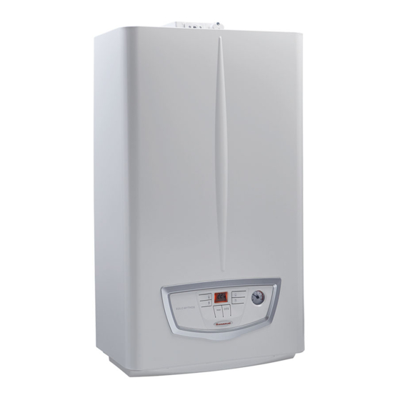
- Page 1 MYTHOS HP Instructions and recommendations Installer User Maintenance technician...
- Page 3 Remote controls and room chrono-thermostats Initial check ................ 45 (Optional) ................16 Yearly appliance check and maintenance ....... 46 1.11 Immergas flue systems ............17 Hydraulic diagram ............. 47 1.12 Tables of resistance factors and equivalent lengths of Wiring diagram ..............48 “Green Range”...
- Page 4 Dear Customer Congratulations for having chosen a top-quality Immergas product, able to assure well-being and safety for a long period of time. As an Im- mergas customer you can also count on a Qualified Technical Assistance Centre, prepared and updated to guarantee constant efficiency of your appliance.
-
Page 5: General Recommendations
Read the instructions provided with the product carefully to ensure proper installation. • This instructions manual provides technical information for installing Immergas products. As for the other issues related to the installation of products (e.g. safety at the workplace, environmental protection, accident prevention), it is necessary to comply with the provisions of the standards in force and the principles of good practice. -
Page 6: Safety Symbols Used
SAFETY SYMBOLS USED GENERIC HAZARD Strictly follow all of the indications next to the pictogram. Failure to follow the indications can generate hazard situations resulting in possible harm to the health of the operator and user in general, and/or property damage. ELECTRICAL HAZARD Strictly follow all of the indications next to the pictogram. -
Page 7: Boiler Installation
The place of installation of the appliance and relative Immergas accessories must have suitable features (tech- nical and structural), such as to allow for (always in safe, efficient and comfortable conditions): - installation (according to the provisions of technical legislation and technical regulations);... - Page 8 These boilers, unless properly isolated, Check that combustion air power supply is free from are not suitable for installation on walls chlorine, sulphur, powders, etc. made of combustible material. Make sure that no chemical substances are stored in the place of installation. Installing the wall recessed frame kit must guarantee If you want to install the product in beauty salons, paint the boiler stable, efficient support.
- Page 9 Filling the condensate drain trap In configuration B22 and B52, unless lo- On first lighting of the boiler, flue gas cal regulations are in force, boilers must may come out the condensate drain; after not be installed in bedrooms, bathro- a few minutes’...
-
Page 10: Main Dimensions
MAIN DIMENSIONS Key (Fig. 2): - Electric connection M - System flow SC - Condensate drain (minimum internal diameter Ø 13 mm) AC - Domestic hot water outlet - Gas supply AF - Domestic hot water inlet - System return Height Width Depth... -
Page 11: Antifreeze Protection
- The materials used for the central heating circuit of Immergas boilers resist ethylene and propylene glycol based antifreeze li- quids (if the mixtures are prepared perfectly). - Page 12 BOILER CONNECTION GROUP FRAME (OPTIONAL) (OPTIONAL) The boiler is designed for installation inside the Immergas reces- The connection unit consisting of all the necessary parts to per- sed frame (supplied as optional). form the hydraulic and gas system connections of the appliance...
-
Page 13: Gas Connection
(i.e. downstream from the pipes connecting the system to the appliance), according to the manufacturer’s instructions. The Immergas connection unit, supplied as an optional kit, also includes the gas cock, whose installation in- structions are provided in the kit. -
Page 14: Hydraulic Connection
To drain the condensate produced by the appliance, it is necessary the IMMERGAS anti-backflow kit to be used upstream of the cold to connect to the drainage system by means of acid condensate re- water inlet connection of the boiler. -
Page 15: Electrical Connection
ELECTRICAL CONNECTION If the power cable is damaged, contact a qualified company (e.g. the Authorised The appliance has an IPX5D protection degree; electrical safety of Technical Assistance Centre) for its re- the appliance is achieved only when it is connected properly to an efficient earthing system, as specified by current safety standards. -
Page 16: Remote Controls And Room Chrono-Thermostats (Optional)
(Fig. 9). stem with the opportunity to easily intervene on the previously set All Immergas chrono-thermostats are connected with 2 wires parameters, without having to go to where the appliance is instal- only. -
Page 17: Immergas Flue Systems
The boiler must be installed with an original Immergas “Green Range” inspectionable air intake system and vi- sible flue gas extraction system made of plastic, with the exception of the C6 configuration, as required by the re- gulations in force and by the product’s approval. - Page 18 Pipe extension in metres Ø When installing horizontal pipes, a minimum inclina- Diaphragm 80/125 horizontal tion of 1.5% towards the boiler must be maintained, and Ø80 (Ref. 1) From 0.35 to 4.2 a section clip with pin must be installed every 3 metres. Ø...
- Page 19 1.12 TABLES OF RESISTANCE FACTORS AND EQUIVALENT LENGTHS OF “GREEN RANGE” FLUE SYSTEM COMPONENTS Equivalent Resistance length TYPE OF DUCT factor in m of concentric pipe Ø 80/125 Concentric pipe 80/125 Ø m 1 90° concentric bend 80/125 Ø Concentric bend 45° Ø 80/125 Terminal complete with concentric horizontal intake-exhaust Ø...
- Page 20 Equivalent Equivalent Resistance Equivalent length in m length in m TYPE OF DUCT factor length in m of concentric pipe of concentric pipe of pipe Ø 80 Ø 60/100 Ø 80/125 Concentric pipe Intake m 17.9 Intake m 7.3 m 3,0 Ø...
-
Page 21: Outdoor Installation In Partially Protected Area
- the flue exhaust must be connected to its own single chimney (B22) or ducted directly outside via a vertical terminal for direct exhaust (B52) or via an Immergas ducting system (B52). The technical regulations in force must be respected. - Page 22 Key (Fig. 13): - Vertical terminal kit for direct exhaust - Intake cover kit The cover kit includes (Fig. 15): No.1 Thermoformed cover No.1 Gasket clamping plate No.1 Gasket No.1 Gasket tightening clip The terminal kit includes (Fig. 15): No.1 Gasket No.1 Exhaust flange Ø...
-
Page 23: Internal Installation Using Arecessed Frame With Direct Air Intake
1.14 INTERNAL INSTALLATION USING A Separator kit installation (Fig. 16). RECESSED FRAME WITH DIRECT AIR 1. Install the discharge flange on the central hole of the boiler, INTAKE positioning the relative gasket with the circular projections downwards in contact with the boiler flange, and tighten using Configuration type B, open chamber and fan assisted the hex screws with flat tip contained in the kit. -
Page 24: Concentric Horizontal Kit Installation
1.15 CONCENTRIC HORIZONTAL KIT Mounting the horizontal intake-exhaust kit Ø 60/100 INSTALLATION (Fig. 18) 1. Install the bend with flange (2) on the central hole of the boiler, Type C configuration, sealed chamber and fan assisted positioning gasket (1) with the circular projections The position of the terminal (in terms of distances from openings, downwards in contact with the boiler flange, and tighten using overlooking buildings, floor, etc.) must be in compliance with the... - Page 25 Mounting the horizontal intake-exhaust kit Ø 80/125 Extensions for Ø 80/125 horizontal kit. Kit assembly (Fig. 21) The kit with this configuration can be extended up to a max. len- (Fig. 20) gth of 11.6 m, including the terminal with grid and excluding the To install the kit Ø...
-
Page 26: Concentric Vertical Kit Installation
1.16 CONCENTRIC VERTICAL KIT INSTALLATION Type C configuration, sealed chamber and fan assisted Concentric vertical intake and exhaust kit. This vertical terminal is connected directly to the outside of the building for air intake and flue gas exhaust. The vertical kit with aluminium tile enables installation on terraces and roofs with a maximum slope of 45% (ap- prox. - Page 27 Mounting the vertical kit with aluminium tile Extensions for Ø 80/125 vertical kit (Fig. 25) The kit with this configuration can be extended to a max. straight Ø 80/125 (Fig. 24) vertical length of 16 m, including the terminal. To install the kit Ø 80/125 one must use the flanged If additional components are assembled, the length equivalent to adapter kit in order to install the flue system Ø...
-
Page 28: Separator Kit Installation
1.17 SEPARATOR KIT INSTALLATION C52* - C82 Type C configuration, sealed chamber and fan assisted, separator kit Ø 80/80 This kit allows air to come in from outside the building and the exhaust to exit from the chimney, flue or intubated duct through divided flue exhaust and air intake pipes. - Page 29 1. Mount the components of kit "C9" on the door (A) of the ducting system (Fig. 30). This kit allows an Immergas boiler to be installed in “C92” confi- 2. (Version Ø 125 only) mount the flanged adaptor (11) interpo-...
- Page 30 Technical data The dimensions of the shafts must ensure a minimum gap betwe- en the outer wall of the smoke duct and the inner wall of the shaft: 30 mm for circular section shafts and 20 mm in the event of a square section shaft (Fig.
-
Page 31: Ducting Of Flues Or Technical Slots
90° Ø 80 bends at boiler outlet. structions, provided by the manufacturer and the requirements of the regulations in force. Immergas ducting systems The Ø 80 flexible and Ø 80 rigid “Green Range” ducting systems must only be used for domestic use and with Immergas condensing boilers. -
Page 32: Flue Exhaust To Flue/Chimney
1.21 FLUE EXHAUST TO FLUE/CHIMNEY. 1.22 FLUES, CHIMNEYS AND CHIMNEY CAPS. Flue exhaust does not necessarily have to be connected to a bran- The flues, chimneys and chimney caps for the evacuation of com- ched type traditional flue for type B appliances with natural drau- bustion products must be in compliance with applicable stan- ght (CCR). -
Page 33: System Filling
1.23 SYSTEM FILLING 1.26 BOILER START-UP (IGNITION) 1. Loosen the cap of the automatic vent valve on the circulating To commission the boiler (the operations listed below must only pump. be performed by qualified personnel and in the presence of staff 2. -
Page 34: Circulation Pump
1.27 CIRCULATION PUMP Pump release. If after a long period of inactivity, the circulator is blocked, adjust The appliance is supplied with built-in pump. the screw in the centre of the head in order to manually release the The pump works at a fixed speed both in central heating and in motor shaft. -
Page 35: Kits Available On Request
1.28 KITS AVAILABLE ON REQUEST - System cut-off valve kits with or without inspectionable filter (on request). The boiler is designed for installation of system in- terception cocks to be placed on flow and return pipes of the connection assembly. This kit is very useful for maintenance because it allows to empty just the boiler without having to emp- ty the entire system. -
Page 36: Main Components
1.29 MAIN COMPONENTS Key (Fig. 35): 15 - Negative signal pressure point 16 - Flue pressure switch Sample points (air A) - (flue gases F) 17 - Thermofuse Sealed chamber 18 - Condensing heat exchanger 19 - Primary heat exchanger Flow probe 20 - System expansion vessel... -
Page 37: General Recommendations
INSTRUCTIONS FOR USE AND Do not take apart or tamper with the intake and exhaust MAINTENANCE pipes. GENERAL RECOMMENDATIONS Only use the user interface devices listed in this section of the booklet. Never expose the wall-mounted boiler to direct vapours from a cooking surface. Do not climb on the appliance, do not use the appliance as a support base. - Page 38 If you smell gas in the building: if you smell burning or see smoke coming out of the appliance, switch it off, discon- – close the gas meter interception device nect power, close the main gas cock, open or the main interception device; the windows and call an authorised com- –...
-
Page 39: Cleaning And Maintenance
CLEANING AND MAINTENANCE To preserve the boiler's integrity and keep the safety fea- tures, performance and reliability, which distinguish it, unchanged over time, you must execute maintenance operations on a yearly basis in compliance with what is stated in the relative point at “annual check and mainte- nance of the appliance”... - Page 40 BOILER USE Solar operating mode By selecting this function, the boiler is set to be used with solar panels. Boiler activation If parameter P03 is set to "solar" mode, the shutdown is related to Before ignition make sure the heating system is filled the set DHW set.
-
Page 41: Fault And Anomaly Signals
2.5 FAULT AND ANOMALY SIGNALS The boiler signals any anomalies using a code shown on the boiler display (11) according to the following table: Error Anomaly signalled Cause Boiler status / Solution Code In the event of request of room central heating or domestic hot water production, the boiler does not switch on within No ignition block the preset time. - Page 42 Error Anomaly signalled Cause Boiler status / Solution Code Disconnect and reconnect the power to the boiler. If the Remote Control is This occurs if an incompatible remote control is connected, Loss of remote control not detected on re-starting the boiler or if communication between the boiler and the remote communication will switch to “Summer”...
-
Page 43: Information Menu
INFORMATION MENU Pressing the buttons “ and “ simultaneously for 5 seconds, the “Information menu” is activated, which displays some boiler fun- ctioning parameters. Press buttons “ ” and “ ” to scroll through the various parame- ters. To exit the menu, press buttons “ ” e “ ” simultaneously again for 5 seconds or wait for 5 minutes. -
Page 44: Boiler Switch-Off
Never leave the boiler switched on if left unused for prolonged pe- using anti-freeze liquid and installation of the Immergas Antifre- riods. eze Kit in the boiler. -
Page 45: Initial Check
Immergas spare parts when re- placing components. If additional documentation needs to be consulted for extraordinary maintenance, contact the Authorised After-Sales Service. -
Page 46: Yearly Appliance Check And Maintenance
YEARLY APPLIANCE CHECK AND Gas type CO2 to nominal Q. CO2 to minimum Q. MAINTENANCE 7.3% (± 0,5) 3.95% (± 0,5) 7.9% (± 0,5) 4.7% (± 0,5) The following checks and maintenance should be per- formed once a year to ensure operation, safety and effi- ciency of the appliance over time. -
Page 47: Hydraulic Diagram
HYDRAULIC DIAGRAM Key (Fig. 37): 16 - Air vent valve 17 - Boiler pump DHW probe 18 - System draining valve D.H.W. flow switch 19 - System pressure switch Flow limiter 20 - Safety thermostat System filling valve 21 - Motorized 3-way valve DHW heat exchanger 22 -... -
Page 48: Wiring Diagram
WIRING DIAGRAM Key (Fig. 38): - Domestic hot water temperature increase button - Domestic hot water temperature decrease button - 230 Vac 50 Hz power supply - Heating temperature increase button - Modulation coil On/Off - Heating temperature decrease button - User interface - Ignition transformer - Flow probe... -
Page 49: Troubleshooting
Check that there are no residues of material blocking the flow of conden- exchanger clogged exchanger and siphon clogging. sate. Poor production of Contact Immergas After-Sales Assistance Service that has procedures to DHW heat exchanger clogged. D.H.W. clean the D.H.W. heat exchanger. Low power supply voltage (when the mini- Wait for the power supply voltage to rise;... -
Page 50: Gas Valve Calibration
CONVERTING THE BOILER TO OTHER Burner adjustment must be carried out using a differential "U" or TYPES OF GAS. digital type pressure gauge connected to the pressure socket loca- ted above the sealed chamber (det. 14 Fig. 35) and the gas valve The gas conversion operation must be carried out by an pressure point (det. - Page 51 • wait until the parameter b02 appears (adjustment of the boi- - Correction of boiler nominal heat output calibration. ler nominal heat output). • Press buttons ( ) and ( ) simultaneously for 5 seconds until ''Ma'' + "nu" appears alternately on the display. The boiler starts up in heating mode;...
- Page 52 P.C.B. PROGRAMMING The boiler is prepared for possible programming of several opera- tion parameters. By modifying these parameters as described below, the boiler can be adapted according to specific needs. To access the programming phase, proceed as described below (Parag 2.3): - press buttons ( ) and ( ) for 5 about seconds until the...
- Page 53 Value Parameter Description Range Default Parameter value Not used nG - Methane Set according Gas type The setting of this function is used to adjust the boiler so that to the gas selection it can operate with the correct type of gas. LG - GPL being used 00 - 20...
- Page 54 Value Parameter Description Range Default Parameter value Establishes the power at which the boiler must switch on. 00 = Methane Ignition power The 1st gas valve step soft ignition step can be set. The 00 - 40 20 - GPL ignition power increases as the parameter value is increased.
-
Page 55: Heating Timer
3.10 SOLAR PANELS COUPLING FUNCTION The display of the boiler power percentage alternates The boiler is prepared to receive pre-heated water from a system of with the display of the temperature read by the flow pro- solar panels up to a maximum temperature of 65°C. In any case, it is always necessary to install a mixing valve on the hydraulic cir- cuit upstream of the boiler, on the cold water inlet. -
Page 56: Casing Removal
3.17 CASING REMOVAL 2. Pull the casing (4) towards your and up at the same time to de- tach it from the upper hooks. To facilitate boiler maintenance the casing can be completely re- 3. Undo the 2 front screws (2) and the 2 lower screws (3) which moved as follows: fasten the casing (4);... -
Page 57: Technical Data
TECHNICAL DATA VARIABLE HEAT OUTPUT The power data in the table has been obtained with intake-exhaust pipe measuring 0.5 m in length. Gas flow rates refer to net calorific value below a temperature of 15°C and at a pressure of 1013 mbar. METHANE PROPANE (G20) -
Page 58: Combustion Parameters
COMBUSTION PARAMETERS Gas type Supply pressure mbar (mm H2O) 20 (204) 37 (377) Gas nozzle diameter 0.82 0.48 Flue flow rate at D.H.W. nominal heat output kg/h (g/s) 47 (13.13) 50 (13.81) Flue flow rate at heating nominal heat output kg/h (g/s) 50 (13.81) 51 (14.14) -
Page 59: Technical Data Table
4.3 TECHNICAL DATA TABLE Domestic hot water nominal heat input kW (kcal/h) 23.8 (20502) Central heating nominal heat input kW (kcal/h) 23.8 (20502) Minimum heat input kW (kcal/h) 9.8 (8423) Domestic hot water nominal heat output (useful) kW (kcal/h) 22.6 (19436) Central heating nominal heat output (useful) kW (kcal/h) 22.6 (19436) -
Page 60: Key For Data Nameplate
KEY FOR DATA NAMEPLATE Cod. Md Sr N° Cod. PIN Type Qnw/Qn min. Qnw/Q max. Pn min. Pn max. Class CONDENSING The technical data is provided on the data nameplate on the boiler. Model Cod. Md Model code Sr N° Serial Number Check Cod. - Page 61 24,510 Contact information IMMERGAS S.p.A. Priemyselná ul. 4789, Poprad-Matejovce 05951 (*) High temperature mode means 60°C on return and 80°C on flow. (**) Low temperature mode for condensation Boilers means 30°C , for low temperature boilers 37°C and for other appliances 50°C of return temperature.
- Page 62 PRODUCT FICHE (IN COMPLIANCE WITH REGULATION 811/2013) Mythos HP Parameter value Annual energy consumption for the central 75,9 GJ heating mode (QHE) Annual electricity consumption for the domestic 40 kWh hot water function (AEC) Annual fuel consumption for the domestic hot...
- Page 63 PARAMETERS FOR FILLING IN THE PACKAGE FICHE In case you should wish to install an assembly, starting from this boiler, use the assembly charts in (Fig. 44 and 46). To complete it properly, fill the relevant spaces as shown in the assembly chart facsimile (Fig. 43” and “45) with the values shown in tables "Parameters for filling in the assembly chart"...
- Page 64 Parameters for filling in the assembly chart Parameter MYTHOS HP "I" "II" "III" 1,18 "IV" 0,46 * to be established by means of table 5 of Regulation 811/2013 in case of “assembly” including a heat pump to integrate the boiler. In this case the boiler must be considered as the main appliance of the assembly.
- Page 65 Facsimile for filling in the domestic hot water production system package fiche ista ‘I’ rato: Contributo solare Dalla scheda del dispositivo solare Elettricità ausiliaria ( 1,1 x ‘I’ 10 % ) ‘II’ ‘III’ - ‘I’ n condizioni climatiche medie climatiche medie <...
- Page 66 Parameters for filling in the DHW package fiche Parameter MYTHOS HP "I" "II" "III" * to be determined according to Regulation 811/2013 and transient calculation methods as per Notice of the European Community no. 207/2014. Domestic hot water production system package fiche.
- Page 68 Immergas Europe S.r.o. 059051 Poprad - Matejovce - SK Tel. +421.524314311 Fax +421.524314316 UNI EN ISO 9001:2015 CERTIFIED QUALITY SYSTEM Design, manufacture and after-sales assistance of gas boilers, gas water heaters and relative accessories...