Table of Contents
Advertisement
Quick Links
Dry-Contact switch Installation Guide
Overview
The SolarEdge Smart Energy Management solutions allow increasing the self-consumption of a site. One
method used for this purpose is controlling the usage (consumption) of loads using Device Control
products.
The SolarEdge Device Control units divert power to an appliance (load) according to pre-configured
schedules, using the following modes:
Schedule - TThe device turns on and off at times set by the user for the user's convenience,
l
regardless of available PV
Smart Save - The device (typically a boiler or water pump) is controlled automatically to maximize self-
l
consumption. Grid power is used only if PV power is insufficient to meet the user's "ready by" time. For
example, to heat water for 2 hours and have hot water by 18:00, set Total Time to 2 hours and Ready by to
18:00. The boiler may work before 16:00 if there is available PV power, but in any case you are guaranteed
to have hot water by
Refer to Figure 2 for examples of the device modes of operation.
You can re-configure the schedules at any time and manually switch appliances on and off.
You can configure the Device Control products locally through the SolarEdge inverter or remotely, via
the SolarEdge monitoring portal.
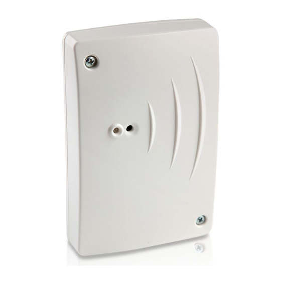
The SolarEdge Dry-Contact switch (referred to as "the device") is a ZigBee wireless load management
device. It switches loads (e.g. a heat pump) on and off according to system configuration. It can function
as an AC switch or as a control signal to indicate when the PV system is producing excess energy. It
supports a wide input voltage range of up to 250V and a wide input current range of up to 13A.
SolarEdge-Dry-Contact switch Installation Guide
power.w
18:00.w
Figure 1: SolarEdge System with Dry-Contact switch
Dry-Contact switch Installation Guide
1
Advertisement
Table of Contents

Related Manuals for SolarEdge Dry-Contact switch


Summary of Contents for SolarEdge Dry-Contact switch
- Page 1 You can configure the Device Control products locally through the SolarEdge inverter or remotely, via the SolarEdge monitoring portal. The SolarEdge Dry-Contact switch (referred to as "the device") is a ZigBee wireless load management device. It switches loads (e.g. a heat pump) on and off according to system configuration. It can function as an AC switch or as a control signal to indicate when the PV system is producing excess energy.
-
Page 2: Installation
Note that in Smart Save mode, the consumption is reduced by taking advantage of excess PV earlier in the day. Figure 2: Examples of device operation To enable the Dry-Contact switch functionality, the following supporting devices must be installed: Device Control ZigBee Module, installed inside the inverter. For physical installation refer to http://www.solaredge.com/sites/default/files/se-device-control-zigbee-module-installation- guide.pdf. - Page 3 3. Drill the holes and mount the device using screws and nuts. Fasten the unit to the wall. 4. Release the three internal screws at the bottom of the device, and remove the cable bracket. Figure 4: Dry-Contact switch connections SolarEdge-Dry-Contact switch Installation Guide MAN-01-00278-1.1...
- Page 4 P r o t o c o l < H A M > P A N S c a n C h a n n e l L o a d D e f a u l t s SolarEdge Dry-Contact switch Installation Guide...
- Page 5 5. Select Add Devices to start the device association with the inverter. 6. Press the association button on the Dry-Contact switch (see Figure 1). The Device Manager screen should display a new line for each discovered device, including the 3 last digits of its serial number, operating mode and operating state.
- Page 6 Min ON Time - (optional); the minimum duration (in minutes) the appliance should remain ON once switched on, even when no excess PV power is available. The default value is 1 minute.e SolarEdge Dry-Contact switch Installation Guide...
- Page 7 D a y s < 1 2 3 4 5 6 7 > Start/Stop Time - the time of day by which the Dry-Contact switch must start/complete its task of delivering energy to the load (default: 00:00; format: hours:minutes). If these values are not set, only the excess PV power is used.
-
Page 8: Verifying The Connection
MAC: the full MAC address of the device Last seen: The date and time when the device communicated with the inverter MFG: The device manufacturer Model: The device model type Power [W]: The energy delivered to the load SolarEdge Dry-Contact switch Installation Guide... -
Page 9: Led Indications
Dry-Contact switch Installation Guide LED Indications The device has a bi-color LED (red/ green) that provides information about its operation status: LED function Indication Solid green (2 seconds), flashing green (2 seconds) Reset Flashing red No ZigBee association with the inverter Flashing green... - Page 10 Remove devices associate more than 10 Remove an unused device from the device list from the device list is devices to the load before attempting to add another device. displayed in the LCD. managemnt network. SolarEdge Dry-Contact switch Installation Guide...
-
Page 11: Specifications
Dry-Contact switch Installation Guide Specifications ELECTRICAL SERVICE Operating Voltage Range - Line to Neutral 90 - 250 AC Frequency 50/60 Maximum Load Current Dry-contact Voltage Range 0-250 COMMUNICATION Supported Communication Protocol ZigBee Home Automation Nominal Transmit Power Operating Frequency Range 2.4 - 2.5...