
Related Manuals for Ricoh BR-C1a Basic


Summary of Contents for Ricoh BR-C1a Basic
- Page 1 BR-C1 Training D179/D180/D181 Service Training BR-C1 Version 1.0 Slide 1 This course explains the new series of high-end black-and-white copiers BR-C1. These new models are successors to the Katana series.
-
Page 2: Service Training
BR-C1 Training D179/D180/D181 Service Training Product Overview Slide 2 This section provides an overview of the machine, and the options that can be installed. - Page 3 Three Models BR-C1a SP (D179), BR-C1a Basic (D179, N. America only) 95 ppm (A4/LT LEF) The BR-C1a Basic for N. America does not have scanner and printer units built in. It can be upgraded with a printer/scanner kit.
-
Page 4: Basic System
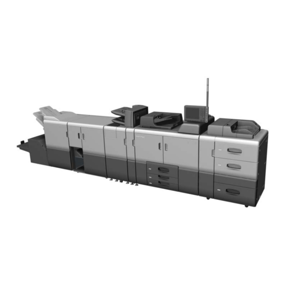
BR-C1 Training Basic System A4/LT LCIT Finisher SR5050 RT5070 The ADF (single-pass duplex) is built in. Slide 4 This shows minimal optional peripherals attached. - Page 5 BR-C1 Training Full System - 1 5. Multi-Folding Unit FD5020 1. Main Machine 6. Ring Binder RB5020 2. LCIT RT5080 (A3) 7. Booklet Finisher SR5060 3. Multi Bypass Tray BY5010 8. Trimmer Unit TR5040 4. Cover Interposer Tray CI5030 Slide 5 ...
- Page 6 BR-C1 Training Full System - 2 5. Perfect Binder GB5010 1. Main Machine 6. Cover Interposer Tray for 2. LCIT RT5080 (A3) Perfect Binder Type S1 3. Multi Bypass Tray BY5010 7. Booklet Finisher SR5060 4. Transit Pass Unit for Perfect Binder Type S1 ...
- Page 7 BR-C1 Training Full System - 3 1. Main Machine 2. LCIT RT5080 (A3) 3. Multi Bypass Tray BY5010 4. Multi-Folding Unit FD5020 5. Booklet Finisher SR5060 6. Trimmer Unit TR5040 Slide 7 No additional notes...
- Page 8 BR-C1 Training Full System - 4 1. Main Machine 2. LCIT RT5080 (A3) 3. Multi Bypass Tray BY5010 4. Cover Interposer Tray CI5030 5. Booklet Finisher SR5060 Slide 8 No additional notes...
- Page 9 BR-C1 Training Rules About Installing Peripherals Either of the two LCITs can be installed on the right side of the main machine. The Multi Bypass Tray can be installed on top of either LCIT. The Decurl Unit is installed inside the main machine. ...
- Page 10 BR-C1 Training Options: Paper Feed Also used with these Similar to: Note models: D517: Multi Bypass Tray Taurus-C1 BY5010 D732: LCIT RT5080 Taurus-C1 D733: LCIT RT5070 Katana-C2 D738: Cover Interposer Tray Taurus-C1 CI5030 Slide 10 No additional notes...
- Page 11 BR-C1 Training Options: Finishing Also used with these Similar to: Note models: D735: Finisher SR5050 Taurus-C1, Katana-C2 D734: Booklet Finisher SR5060 Taurus-C1, Katana-C2 D449: Punch Unit PU5020 Taurus-C1, Katana-C2 For D734/D735 D736: Perfect Binder GB5010 Aegis/Aries D736: Cover Interposer Tray for Katana-C2 Perfect Binder Type S1 D736: Transit Pass Unit for...
- Page 12 BR-C1 Training Options: Controller Also used with these Similar to: Note models: D726: Postscript3 Unit Similar to those Type S1 used with other models D726: SD card for NetWare printing Type S1 D726: Browser Unit Type D726: IPDS Unit Type S1 Slide 12 No additional notes...
- Page 13 BR-C1 Training Options: Controller Also used with these Similar to: Note models: D726: Printer/Scanner For BR-C1a Basic only Unit Type S1 D164: IEEE 802.11a/g/n CH-C1, Met-C1 Interface Unit Type M3 D166: OCR Unit Type M2 CH-C1, Met-C1 B679: IEEE 1284 Interface...
- Page 14 BR-C1 Training Options: EFI Controller Also used with these Similar to: Note models: D726: Printer Controller EB-32 Slide 14 No additional notes...
- Page 15 BR-C1 Training Options: Other Also used with these Similar to: Note models: B328: Copy Connector Katana-C2 Type 3260 B870: Optional Counter Used with many other models Interface Unit Type A B452: Key Counter Bracket Type 1027 Slide 15 No additional notes...
-
Page 16: Operation Panel
BR-C1 Training Operation Panel 10.4-inch LCD touch panel Customizable display Slide 16 Same as Ch-C1 and Met-C1. There is no Smart Operation Panel option with Android OS. - Page 17 BR-C1 Training Similarities with Other Models - 1 ADF: Similar to CH-C1 Scanner: Similar to CH-C1 Image Processing: Similar to CH-C1 Laser Unit: Similar to Taurus-C1 Toner Supply: New Photoconductor Unit (PCU): Similar to Aries-C1.5/P-1.5 ...
- Page 18 BR-C1 Training Similarities with Other Models - 2 Paper Transfer: Similar to Taurus-C1 Paper Transport Belt: Similar to Taurus-C1 Fusing Unit: New Paper Feed Unit: Similar to Katana-C2 Paper Registration: Similar to Taurus-C1 Paper Switch Back and Duplex Pass unit: Similar to Taurus-C1 ...
- Page 19 BR-C1 Training SD Cards When the machine is shipped from the factory, the printer/scanner card is in slot 1 (except for the basic model: USA only). Do not remove this card from slot 1. Options on SD cards must be moved to the card in slot 1. ...
-
Page 20: Important Specifications
BR-C1 Training Important Specifications - 1 Engine speed (plain paper, A4/LT LEF) C1a: 95 ppm (A4/LT LEF) C1b: 110 ppm (A4/LT LEF) C1c: 135 ppm (A4/LT LEF) Warm-up time: Less than 360 sec. (23C, 73.4F) ... - Page 21 BR-C1 Training Important Specifications - 2 Input Paper Size Tray 1: A4 (LEF) and LT (LEF) Trays 2 and 3: A3 SEF to A5 LEF, B4 SEF to B5 LEF,11x17 SEF to 5.5x8.5 LEF » Custom Size Paper –...
- Page 22 BR-C1 Training Important Specifications - 3 Input Paper Weight Tray 1: 52.3 - 256g/m2, 14lb Bond - 95lb Cover Trays 2 and 3: 52.3 - 256g/m2, 14lb Bond - 95lb Cover A4/LT LCIT » Tray 4: 52.3 - 216g/m2, 14lb Bond - 80lb Cover »...
- Page 23 BR-C1 Training Important Specifications - 4 Output Capacity Finisher: 3,000 + 250 sheets Booklet Finisher: 2,500 + 250 sheets Stacker: Not supported RAM: 2 GB HDD: 183 GB x2 (usable area), 250 GB x2 actual disk size Slide 23 No additional notes...
- Page 24 BR-C1 Training Yield of Consumables Toner: 82K 6% coverage A4 LEF P/J 35 (BR-C1a), 45 (BR-C1b), or 55 (BR-C1c) Image density level: 1.5 Developer: 860k Used toner bottle: 1200k Slide 24 No additional notes...
- Page 25 BR-C1 Training Targets Average Document Volume: BR-C1a: 100 k BR-C1b: 150 k BR-C1c: 250 k Maximum Print Volume: 1,000 k PM cycle: 600 k Machine Life: 60,000 k or 5 years Slide 25 ...
-
Page 26: Service Training
BR-C1 Training D179/D180/D181 Service Training New and Improved Features Slide 26 No additional notes... - Page 27 BR-C1 Training Basically the same as the CH-C1 series with the addition of a double-feed sensor. This sensor uses ultra-sound. This ADF is a single-pass duplex scan model. Slide 27 No additional notes...
- Page 28 BR-C1 Training LD Unit Components (VCSEL Technology) A VCSEL LD unit has 40 beams in a two-dimensional array. VCSEL allows magnification correction and fine adjustment of image position. VCSEL also keeps the strength of the laser beams constant by optical waveform correction.
- Page 29 BR-C1 Training Benefits of VCSEL Technology When printing duplex, some media/paper may shrink or expand after the front page goes through the fusing unit. Such changes in paper size may result in inaccurate registration on the front and back pages.
- Page 30 BR-C1 Training VCSEL Laser Technology Main Scan Magnification Correction In duplex mode, some paper may shrink or enlarge after it goes through the fusing unit, and this change in paper size may result in inaccurate registration between the front and back pages.
- Page 31 BR-C1 Training VCSEL Laser Technology Optical Waveform Correction Without Correction With Correction VCSEL technology ensures that a constant current is applied to the laser diode. The effects of this are clear when printing thin diagonal lines. Slide 31 No additional notes...
-
Page 32: Drum Charge
BR-C1 Training Drum Charge A Scorotron corona unit is used, not a charge roller. Slide 32 No additional notes... - Page 33 BR-C1 Training Smaller Toner Particles Katana-C2 BR-C1 The new toner has smaller and more uniform particle size than the Katana series. The new toner also makes a lower toner pile height, which contributes to lower toner consumption. Slide 33 ...
- Page 34 BR-C1 Training Two Toner Bottles There are two toner bottles. The customer can replace one bottle while the machine is printing. Slide 34 No additional notes...
- Page 35 BR-C1 Training Transfer Belt System similar to Color Engines Drum Transfer Belt Transfer Roller This method does the following, compared with the Katana series: Eliminates scratch marks made by drum stripper pawls Improves halftone images, in conjunction with new process control for black-and- white copiers ...
- Page 36 BR-C1 Training ITB Separation Rotating a lever up and down raises and lowers the ITB against and away from the drum. There is no motor or separation mechanism to separate the belt and drum when the machine is idle.
- Page 37 BR-C1 Training ITB Centering Control A sensor at the upper right corner of the ITB unit monitors the rear edge of the belt to check its position. If the belt goes off center, a motor, roller, and cable mechanism corrects the position of the belt.
- Page 38 BR-C1 Training Easier to Pull Out the Inner Unit The inner unit is unified in one drawer (opened from the front). It contains all the paper path units for registration, paper separation, paper transport to fusing unit, fusing unit, cooling, and the exit/inverter unit.
- Page 39 BR-C1 Training No Separation Roller Solenoid The machine has no solenoid to lift and lower the separation roller in the paper feed units. When a tray is opened and closed, a lever lowers and raises the separation roller. ...
- Page 40 BR-C1 Training Flatter Paper Path Improved support for thick paper. Fewer jams Slide 40 No additional notes...
- Page 41 BR-C1 Training Productivity for Thick Paper BR-C1a A4: 95 ppm for all sizes A3: 52 ppm for all sizes BR-C1b A4: 110 ppm for all sizes up to 256 g/m2, 95 ppm if over 256 g/m2 ...
- Page 42 BR-C1 Training Mechanical Paper Registration Unit Skew Correction The gates that stop paper for skew correction are mounted on a roller that is driven by the registration timing motor. This replaces the vertical "elevator" gate. Slide 42 No additional notes...
- Page 43 BR-C1 Training Mechanical Paper Registration Unit Image Registration There are two shift units used to position the paper for image registration. The leading edge shift unit [A], near the leading edge of the paper at the registration gate roller, grips the paper and adjusts the position in the main scan direction.
- Page 44 BR-C1 Training Main and LCT Relay Rollers The opening and closing of the main relay rollers and LCT relay rollers is controlled by two separate motors, not solenoids. These rollers are separated to free the paper for image registration.
- Page 45 BR-C1 Training Bigger Print Area Up to 13”x19.2” and SRA3 are supported. BR-C1 supports SRA3 as a standard paper size. The maximum supported paper size is 13”x19.2”. 13”x19.2” is supported by trays 4-6 of (A3/DLT LCT) and tray 7 (By-pass tray). ...
- Page 46 BR-C1 Training Double-feed Sensor In some earlier models, a sensor using light was used for this purpose. But the light beams had trouble going through heavy paper types. So the BR-C1 is using a sensor that uses ultrasound. Slide 46 No additional notes...
- Page 47 BR-C1 Training PTB Unit The number of paper transport belts and transport fans has been reduced from three to two. Slide 47 No additional notes...
- Page 48 BR-C1 Training Belt Fusing Unit The fusing system is based on Taurus-C1/P1. It has a soft belt mechanism, compared to the Katana-C2 hard roller. This improves paper handling for thin/thick paper, textured, and coated paper. Also, the belt fusing unit has a paper separation plate instead of stripper pawls used with the Katana series.
- Page 49 BR-C1 Training Cooling around the Fusing Unit Ducts around the fusing unit carry air to reduce the heating from the fusing unit on other parts of the engine. Slide 49 No additional notes...
- Page 50 BR-C1 Training Cooling Belts The number of cooling belts on the left side of the fusing unit has been reduced to one. Slide 50 No additional notes...
- Page 51 BR-C1 Training TCRU The following are TCRU items for this machine. TCRU Set A » OPC Drum » Developer » ADF Feed Roller Unit » Charge Corona Unit » Paper Transfer Roller Unit » Belt Cleaning Unit » Fusing Cleaning Unit »...
- Page 52 PP Media released to the field RCL publish updated SERES Media List and Paper Library about once a month Upload paper library to RICOH machine via SD card Download Service RAC/RE/ RA/RCN Download Paper Library to SD Card OpCo Slide 52...
- Page 53 BR-C1 Training Improvements to the Paper Library Schematic of Integrated Media Setting System Download SP5-711-102 Upload SP5-711-002 machine Back Up By TC Upload SP5-711-001 Automatically Synchronizes Register by Register by media name media type & Save & Restore weight Configure Configure Configure Back Up &...
- Page 54 BR-C1 Training Improvements to the Paper Library Each Model (A/B/C) has Different Paper Catalog Data Aries 1.5 Taurus 1 CH C1 Pro Baron C1 Copy Copy A model A model A model Printer B model ...
- Page 55 BR-C1 Training Improvements to the Paper Library New Operation Flow & User Interface: Paper Tray Main Menu Screen There is enough room to display longer paper names and tray information. Real custom size is shown on the main screen ...
- Page 56 BR-C1 Training Improvements to the Paper Library New Operation Flow & User Interface: Paper Setting Tray Screen Make manual settings for the paper in a tray, Direct way to change and make a new settings for a custom paper profile ・Custom Paper Settings ・Advanced Settings Select a...
- Page 57 BR-C1 Training Improvements to the Paper Library New Operation Flow & User Interface: Allocating Paper to a Tray The operation has been simplified. Press a tray [1] to allocate a paper type to the tray. Select a custom paper type [2] and press OK.
- Page 58 BR-C1 Training Improvements to the Paper Library New Operation Flow & User Interface: Managing the Custom Paper Library Sort & Search functions are provided Custom Paper settings can be printed Direct Access to Paper Library & Saved Paper Library from Custom Paper Screen ...
- Page 59 BR-C1 Training Improvements to the Paper Library New Operation Flow & User Interface: Pop-up Windows This window appears during the following operations. (Examples) Change custom paper settings (Do not Save / Overwrite / Save as) Recall from Paper Library to Custom Paper (No / Yes) ...
- Page 60 BR-C1 Training Improvements to the Paper Library New Operation Flow & User Interface: Paper Library: Multiple Selection It is possible to select more than two paper types at the same time when recalling from the library. Slide 60 No additional notes...
- Page 61 BR-C1 Training Improvements to the Paper Library New Operation Flow & User Interface: Back-up and Restore the Custom Paper via SD Card - 1 1. Insert the SD card into the SD slot on the operation panel. 2. From [User Tools], select [Adjustment Settings for Skilled Operators].
- Page 62 BR-C1 Training Improvements to the Paper Library New Operation Flow & User Interface: Back-up and Restore the Custom Paper via SD Card - 2 4. Select [0520: Backup / Restore Custom Paper Data]. 5. Select either [Back Up Saved Paper Library] or [Back Up Custom Paper Settings] or [Restore Custom Paper Settings]...
- Page 63 BR-C1 Training Improvements to the Paper Library New Operation Flow & User Interface: Printing out Custom Paper Setting Information - 1 In the paper library top screen, touch “Print the Settings”. Slide 63 No additional notes...
- Page 64 BR-C1 Training Improvements to the Paper Library New Operation Flow & User Interface: Printing out Custom Paper Setting Information - 2 Select a paper type and press “Print”. Then touch the Start key on the operation panel. Slide 64 No additional notes...
- Page 65 BR-C1 Training Improvements to the Paper Library New Operation Flow & User Interface : GW Printer Driver Supports Custom Paper Selection Custom Paper can be selected in the pull-down menu for paper type . Slide 65 No additional notes...
-
Page 66: Power On/Off Timer
BR-C1 Training Power On/Off Timer Working Consumption Ready Power On Power Off Sleep mode Power Off Sleep Time Working hours Night Power Off 8:00 24:00 The previous On/Off timer only supports shifting to sleep mode at the specified time. But in this model, the machine can also automatically turn power on/off at the specified time. - Page 67 BR-C1 Training Replaceable Power Cord The power cord from the main frame is replaceable, so that it is easier to adapt the machine for local power outlets. Slide 67 No additional notes...
- Page 68 BR-C1 Training Capturing Debug Logs on an SD Card Common problems encountered when capturing logs: Requires a PC and exclusive cable Captured logs are somehow lost Logs are deleted when powering off the machine Also, for data security reasons, customers are beginning to prohibit field technicians from connecting their laptop PCs to the machines.
- Page 69 BR-C1 Training Capturing the Debug Logs Controller and Operation Panel - 1 Logs for the controller and operation panel can be transferred to an SD card in the SD slot on the operation panel. These logs can help solve problems caused by the software.
- Page 70 BR-C1 Training Capturing the Debug Logs Controller and Operation Panel - 2 Insert the SD card into the slot on the side of the operation panel. Set the start date of the log with SP5-857-101 e.g.: March 28, 2013: input 20130328 (yyyymmdd) ...
- Page 71 BR-C1 Training Capturing the Debug Logs Controller and Operation Panel - 3 The logs are saved with the following file names and paths. Controller log (GW debug log): /LogTrace/machine number/watching/ yyyymmdd_hhmmss_unique identification number.gz Operation panel log: /LogTrace/machine number/opepanel/ yyyymmdd_hhmmss.tar.gz Slide 71 No additional notes...
- Page 72 BR-C1 Training Capturing the Debug Logs Engine Log and Debug Log - 1 Engine logs In previous machines, the engine log is captured by entering the “LOG” command from the TeraTerm software on a PC connected to the machine. ...
- Page 73 BR-C1 Training Capturing the Debug Logs Engine Log and Debug Log - 2 Compatible SD card types SD card (up to 2GB): Supported SDHC (4 to 32GB, Class 2 to 10): Supported SDHC (4 to 32GB、UHS-i, ii): Not supported (excess electrical current) ...
- Page 74 BR-C1 Training Capturing the Debug Logs Engine Log and Debug Log - 3 For these logs, we have to connect an SD card to the SD card slot on the SDCB. The SDCB is fixed to the frame and connected to the IOB with a harness.
- Page 75 BR-C1 Training Capturing the Debug Logs Engine Log and Debug Log - 4 Preparing the machine to collect logs 1. Turn off the machine power. 2. Open the rear controller box, set the SDCB with attached SD card slot on the frame, connect the SDCB to the IOB with a harness, and insert the SD card into the slot.
- Page 76 BR-C1 Training Capturing the Debug Logs Engine Log and Debug Log - 5 The system generates log files automatically from the time the machine power is turned on until it is turned off. When reaching maximum capacity (engine log: 512KB, debug log: 8MB), new log files will be generated automatically.
- Page 77 BR-C1 Training Capturing the Debug Logs Engine Log and Debug Log - 6 SP5-901-001/002: Displays the names of the saved engine and debug log files. This SP will appear blank if the SD card is not inserted or the log save option is set to off.
- Page 78 BR-C1 Training Embedded OCR (Searchable PDF) Overview Copy & Paste Search Scanning This function lets users add transparent text information on scanned documents. Searchable PDF is composed of two layers; Image-Layer and Text Layer. User can search specific words by using electronic search functions. ...
- Page 79 BR-C1 Training Embedded OCR (Searchable PDF) Notes about this Feature OCR can recognize texts even when there are multiple languages (easy words) in the scanned documents. When users choose Searchable PDF, invisible texts will be embedded in scanned images after scanning all input documents.
-
Page 80: How It Works
BR-C1 Training Embedded OCR (Searchable PDF) How it Works User Operations • Users’ basic operation does not differ from other scanner settings. • This function supports the following file types: PDF, High Compression PDF, and PDF/A. Send Searchable PDF to email •... - Page 81 BR-C1 Training Embedded OCR (Searchable PDF) Remarks - 1 This function is provided as an option. Some models require a HDD option. Searchable PDF files cannot be stored in the Document Server. Preview cannot be used for Searchable PDF files. ...
- Page 82 BR-C1 Training Embedded OCR (Searchable PDF) Remarks - 2 When the scan resolution is set below 200dpi, OCR quality may not be good enough to create a Searchable PDF. As a result, Searchable PDF cannot be used when the resolution is set less than 200dpi.
-
Page 83: Service Training
BR-C1 Training D179/D180/D181 Service Training Improvements to the Options Slide 83 No additional notes... - Page 84 BR-C1 Training Large Capacity Trays The A3 and A4 LCTs are the same height as the main machine, so it is easy to install the optional bypass feeder. Slide 84 No additional notes...
- Page 85 BR-C1 Training Decurler is Easier to Use The decurler unit is integrated in the mainframe, which is the same as Aries/Taurus. The level of the decurling force can be set from the operation panel. The customer can switch from back curl/face curl mode automatically without the physical operation that was necessary for the decurler unit of Katana-C2.
- Page 86 BR-C1 Training Folder The auxiliary tray and flexible page depressor are no longer accessories; they are built into the unit. The auxiliary tray keeps Z-folded paper flat in the tray so that the trailing edges do not trigger an early tray full alert in the top tray.
- Page 87 BR-C1 Training Finisher Improved productivity in stapling mode, because the capacity of the pre-stack tray is increased. Air-assisted paper delivery has been added for the shift tray, to improve stacking for large-size coated paper. The staple unit has a new mechanism to move the bottom fence up and down slightly, to allow the stapling position to be adjusted (this is a TCRU adjustment).
- Page 88 BR-C1 Training D179/D180/D181 Service Training Installation Main Machine Slide 88 The following slides just show the important points about installation. For full details, see the procedures in the service manual. Follow the steps carefully. Observe all notes and cautions in the procedures.
-
Page 89: Outline Of The Procedure
BR-C1 Training Outline of the Procedure Remove Tapes, Shipping Materials Install Operation Panel (Standard Installation, or Easy Access Installation) Status Light Power Cord, Cable Clamp Fusing Roller Knob Holder, ITB Lever, Cleaning Cloth Name Plate, Decals ... - Page 90 BR-C1 Training Factory Values Sheet This is under the original tray. Open the right door and store it inside the machine as shown below. You can keep the SMC sheet here also. Slide 90 No additional notes...
-
Page 91: Installing The Operation Panel
BR-C1 Training Installing the Operation Panel There are two ways to install the operation panel. Standard installation. The operation panel is high enough for a person of average height to operate the machine standing at the front of the machine. - Page 92 BR-C1 Training Fusing Roller Knob Holder Open the left front door [A]. Locate the hole and faint vertical line where the holder will be installed. Peel the cover off the tape on the back of the holder [B].
- Page 93 BR-C1 Training ITB Lever Attach the ITB lift lever, and rotate it up It is not attached to the machine before it is shipped. Make sure that this lever is up. The right front door will not close if this lever is down. Slide 93 No additional notes...
-
Page 94: Leveling The Machine
BR-C1 Training Leveling the Machine There is a wrench in the accessories for adjusting the feet. The big end [A] is for the main machine. The small end [B] is for the peripherals. Slide 94 No additional notes... - Page 95 BR-C1 Training Breaker Switch Test - 1 The breaker switch is at the left rear corner of the machine. Test it at installation. Inspect, clean, and test at least once a year. The Ring Binder and Perfect Binder also each have a breaker switch.
- Page 96 BR-C1 Training Breaker Switch Test - 2 [1] is the normal position of the breaker switch test button. Use the tip of a small screwdriver or pen to push the breaker test button. The breaker switch should flip to the "O" position [2]. This indicates that the breaker switch is operating normally.
- Page 97 BR-C1 Training Install Toner Bottles - 1 The machine is shipped from the factory with toner and carrier already in the development unit. But the toner bottles must be installed at the customer site. The machine power must be off when you start this procedure. 1.
- Page 98 BR-C1 Training Install Toner Bottles - 2 5. Open the toner bank door, insert both toner bottles, and close the toner bank door. 6. Do SP7628-002 (Clear PM Counter). Exit SP mode. 7. Close the left front door. 8. Toner fill will begin automatically after closing the left front door.
-
Page 99: Turning The Power On
BR-C1 Training Turning the Power On Power switch [1] behind the front left door is on when the machine leaves the factory. To turn the power on, at the front left corner of the machine, lift the switch cover and press the operation power switch [2]. -
Page 100: Turning The Power Off
BR-C1 Training Turning the Power Off At the front left corner of the machine, open the cover, press the operation power switch [A], and then close the cover. A message appears and tells you to wait at least 2 min. until the machine powers down completely. -
Page 101: Forced Shutdown
BR-C1 Training Forced Shutdown In case normal shutdown does not complete for some reason, the machine has a forced shutdown function. To make a forced shutdown, press and hold the power switch on the operation panel for 6 seconds. - Page 102 BR-C1 Training Update the Paper Library If you have a more recent paper library than the one in the machine, update the machine. 1. Insert the SD card which has the "library.mqp" file into SD card Slot 2 (lower slot) on the right side of the controller box.
-
Page 103: Paper Tray Heaters
BR-C1 Training Paper Tray Heaters - 1 There are two tray heaters in the paper bank, an upper heater for Tray 1 and a lower heater for Trays 2 and 3. The tray heaters are not pre-installed. They are options that must be installed by the technician. - Page 104 BR-C1 Training Paper Tray Heaters - 2 Locate the bank of white connectors on the back of the AC drive board. Locate the harness for the bank heaters and LCIT heater. The plug can be plugged into either [A] or [B]. ...
- Page 105 BR-C1 Training ITB Heater There is a heater below the image transfer roller. The heater is installed in the factory but not connected. Connect it if image problems caused by low temperature are occurring. See the slide titled ‘Replacement - AC Drive Board Connectors’...
- Page 106 BR-C1 Training Check the Image Area Do these two adjustments in this order: Front/Back Alignment and Magnification Adjustment » This check and adjustment ensures that the image areas on both the front and back sides of the paper are the same size and aligned with one another.
- Page 107 BR-C1 Training After Installing the Machine and All Options After you have finished installing the machine, it might be a good idea to back up the NVRAM to an SD card. Also, it might be a good idea to do this after every service visit.
-
Page 108: Moving The Machine
BR-C1 Training Moving the Machine Before you move the machine, even for a short distance, study the section of the installation procedure titled ‘Moving and Transporting the Machine’. The waste toner path must be cleared. The toner cartridges must be removed. ... -
Page 109: Service Training
BR-C1 Training D179/D180/D181 Service Training Installation Options Slide 109 The following slides just show the important points about installation. For full details, see the procedures in the service manual. Follow the steps carefully. Observe all notes and cautions in the procedures. Note that installation of guide plates, mylars, sponges, and docking brackets depends on which peripherals are connected immediately upstream or downstream. - Page 110 BR-C1 Training Decurler – 1 Install the correct guide plate at the decurler exit, as explained in the manual. Look for a letter A or C embossed on the guide plate. This depends on the next unit downstream of the decurler unit.
- Page 111 BR-C1 Training Decurler - 2 Do these SPs after installing the decurler. SP1927 and 1928: Input the numbers printed on the accessory sheet that is packed with the decurler. SP5804-128: This sets the upper path in the decurler unit as the default paper path.
- Page 112 BR-C1 Training Decurler - 3 Guide Plate A Guide Plate C Adjust the levelling bolts until the parts shown in red are level with the red mark (for type A) or the notch (type C). Do this at the front and the rear. ...
- Page 113 BR-C1 Training Decurler - 4 Make some test copies to check for curl. If the output is curled, correct with SP 1906-001- 007. The settings are as follows: Back Curl 1: Slight Face Curl 2: Excessive Face Curl ...
-
Page 114: Bypass Tray
BR-C1 Training Bypass Tray The Multi Bypass Unit must be installed on the LCIT before the LCIT is docked to the mainframe. If the LCIT is already installed, it must be disconnected from the mainframe before installation of the Multi Bypass Unit. Slide 114 ... - Page 115 BR-C1 Training LCIT - 1 Install the tray heaters before you dock the LCIT with the main frame. Slide 115 No additional notes...
- Page 116 BR-C1 Training LCIT - 2 There are fewer docking pins (previous models: 4, this model: 3) There are two notched joint pins and one smooth joint pin with the accessories. Attach one notched pin on the right side of the main machine at the rear [A], and the other notched pin at the front [B].
- Page 117 BR-C1 Training LCIT - 3 Docking with the main machine: Push the unit toward the right side of the main unit until they are about 15 cm (6 in.) apart. Open the front door of the unit. ...
- Page 118 BR-C1 Training Moving an LCIT To prevent damage to the wires, always disconnect the LCT from the main machine, and disconnect the ground wire and heater (if installed) before you move the machine or the LCT. Full details are in the installation procedure for the LCIT.
- Page 119 BR-C1 Training Finishers - 1 When docking the finisher, the height of the finisher entrance [A] must be at the same height as the upstream unit‘s paper exit [B]. Slide 119 No additional notes...
- Page 120 BR-C1 Training Finishers - 2 Instruct the operator about when to use the auxiliary tray, as explained below. Before feeding Z-folded paper from the Multi Folding Unit, set the Z- fold auxiliary tray on the shift tray. Slide 120 No additional notes...
- Page 121 BR-C1 Training Moving a Finisher Turn the system off and unplug the main machine from the power source. Disconnect the finisher I/F cord from the upstream unit (or main machine). Make sure that the front door of the finisher is closed.
-
Page 122: Punch Unit
BR-C1 Training Punch Unit When you remove the screw (1) that holds the tag [B], install it at location (2). This stabilizes the punch unit. Slide 122 No additional notes... - Page 123 BR-C1 Training Folder - 1 Three parts must be removed before the tray unit of the cover interposer tray can be mounted on top of the Multi Folding Unit. Slide 123 No additional notes...
- Page 124 BR-C1 Training Folder - 2 Raise the auxiliary tray [A] or pull out the flexible page depressor [B] when required. The auxiliary tray [A] keeps Z-folded paper (FM1) flat in the tray so that the trailing edges do not trigger an early tray full alert in the top tray. ...
- Page 125 BR-C1 Training Folder - 3 There are six types of folding. FM1: Z-Fold FM2: Half-fold FM3: Letter Fold-out FM4: Letter Fold-in FM5: Double-parallel Fold FM6: Gate Fold Slide 125 This is the same as previous models. ...
- Page 126 BR-C1 Training Moving the Folder To prevent damage to the connection brackets, never attempt to move or change the position of the system with the LCT, the Multi-Folding Unit, (or any other downstream peripheral) connected. Turn the system off and unplug the main machine from the power source.
-
Page 127: Perfect Binder
BR-C1 Training Perfect Binder Installation is the same as for previous models. Slide 127 No additional notes... - Page 128 BR-C1 Training Ring Binder Correct Lifting Method Do not lift by the top Top Cover: DO cover. This will damage NOT LIFT HERE the cover. Base: Lift here Slide 128 This is the same as Katana-C2.
- Page 129 BR-C1 Training Ring Binder Removing Shipping Materials Do not discard these Braces: Do not braces. throw away They must be reattached to the finisher before it is moved or shipped to another location. Slide 129 This is the same as Katana-C2.
- Page 130 BR-C1 Training Ring Binder Ring Supply Indicator Attach the indicator to the ring supply cartridge. Ring Supply Cartridge Indicator Slide 130 This is the same as Katana-C2.
- Page 131 BR-C1 Training Ring Binder Breaker Switch Test this switch. It is at the bottom of the left rear corner near the power cord. Slide 131 This is the same as Katana-C2.
-
Page 132: Trimmer Unit
BR-C1 Training Trimmer Unit - 1 Stopper Plate Keep this stopper plate. You need to attach it before you move the machine to a new location. Slide 132 This is the same as Katana-C2. - Page 133 BR-C1 Training Trimmer Unit - 2 Small Plate Lock The docking lock is at the rear. In the other peripherals, it is at the front. Remove the small plate in the rear cover to access the lock. Slide 133 ...
- Page 134 BR-C1 Training Side-to-side Registration and Skew Adjustment In models with a long line of finishers attached to the paper exit, these adjustments must be done. The procedure is the same as for previous models. Service Manual > Installation > Common Adjustments ...
- Page 135 BR-C1 Training Embedded OCR (Searchable PDF) Installation - 1 Insert the OCR SD card in slot 2 Turn the main switch on. Execute SP 5-878-004 (Option setup: OCR dictionary) Turn the switch off and on. Execute SP 5-878-004 again (Option setup: OCR dictionary) ...
- Page 136 BR-C1 Training Embedded OCR (Searchable PDF) Installation - 2 The machine’s serial number is saved on the OCR SD card during the first execution of SP5-878-004. At the same time, the OCR option’s serial number is saved in the machine’s NVRAM (on the controller board).
- Page 137 BR-C1 Training Embedded OCR (Searchable PDF) Troubleshooting The searchable PDF function is saved on the HDD and the SD card ID is saved in NVRAM. After replacement of either the HDD unit or the NVRAM, OCR Unit must be installed again. ...
-
Page 138: Service Training
BR-C1 Training D179/D180/D181 Service Training Maintenance Slide 138 This section takes a quick look at the PM table, and new features related to PM. Cleaning, lubrication, and replacement procedures are in the Replacement and Adjustment section of the service manual. Important points will be mentioned during the course. - Page 139 BR-C1 Training PM Intervals - 1 ADF: Replace the feed belt and reverse roller at 100k originals Replace the pick-up rollers at 120k originals Lubricate the feed drive gear (EM-50L grease) Clean other parts Scanner: ...
- Page 140 BR-C1 Training PM Intervals - 2 Development unit: 600k: Clean doctor blade, gears, vent filter and toner supply unit » Do not use a vacuum cleaner on the vent filter. 860k: Replace developer » Clean doctor blade when replacing developer. ...
- Page 141 BR-C1 Training PM Intervals - 3 Paper feed, registration unit, paper exit, duplex 100k: Cleaning for pickup, feed, and separation rollers, and sensors: every 100k as necessary 600k, then every 300k after that: Cleaning for other rollers, vertical transport unit, CIS, paper dust collection tray as necessary ...
- Page 142 BR-C1 Training PM Intervals - 4 Fusing unit cleaning 600k: Fusing belt stripper plate, pressure roller stripper plate, entrance guide plate, hot roller separation plate, pressure roller pick-off pawls 1000k: Fusing unit entrance guide, heating roller thermistor, pressure roller thermistor, main gears, hot roller bearings, heating roller bearings ...
- Page 143 BR-C1 Training New Functions in the PM Counter Display New features on the PM counter display allow you to see the following: Estimated usage rate / Remaining days (with relation to PM yield) Commissioning Status Report Slide 143 ...
- Page 144 BR-C1 Training Page Counter and Running Distance Slide 144 No additional notes...
- Page 145 BR-C1 Training Page Counter and Running Distance PM parts yield is based on the page counter (K) when the customer prints using the target conditions. But, for most PM parts, the yield depends on running distance See the formula below for how this is calculated.
- Page 146 BR-C1 Training Estimated Value Display [A]: Number buttons. Pressing a number button opens a submenu. [B]: Descriptions. The # mark denotes a “unit” (not individual items). [C]: Displays the estimated usage rate (0~100%) [D]: Displays the estimated remaining days (255~0 days) ...
- Page 147 BR-C1 Training Estimated Usage Rate Display Displays the larger of these two values: Page counter (SP7-954-xxx), and running distance (SP7-942-xxx). Note that parts such as rollers are displayed using the page counter value since running distance is not measured. Estimated usage rate % by page counter = A/B*100 A: Current page counter value (SP7-621-xxx) B: Standard page end value (SP7-623-xxx)
- Page 148 BR-C1 Training Estimated Remaining Days Display Displays the smaller of these two values: Page counter (SP7-951-XXX), and running distance (SP7-952-XXX). Note that parts such as rollers are displayed using the page counter value since running distance is not measured. Remaining days by page counter (SP7-951-XXX) = (A –...
- Page 149 BR-C1 Training Commissioning Status Report You can print the Status Report to check the machine status. 1. SP7403-001~010 SC History 2. SP7507-001~010 Printer Engine Jam History 3. SP7508-001~010 Original Jam History 4. SP7810-255 ROM No 5. SP7810-255 Firmware version 6.
- Page 150 BR-C1 Training Caution when Replacing Parts There are two types of commonly used screws: blue and silver. Always remove and re-install blue screws at their original location. Always remove and re-install silver screws at their original location. ...
- Page 151 BR-C1 Training PM Counter Reset Timing For some recent models, the PM counter is reset before replacing the part. However, for BR-C1, replace the part first, then reset the counter. Slide 151 No additional notes...
-
Page 152: Service Training
BR-C1 Training D179/D180/D181 Service Training Machine Overview Slide 152 No additional notes... -
Page 153: Overall Layout
BR-C1 Training Overall Layout Slide 153 1. Status Light 2. Operation Panel 3. ADF 4. Scanner 5. ITB Cleaning Unit 6. Fusing Unit 7. PTB (Paper Transport Belt) 8. Invert/Exit Unit 9. Purge Path 10. Toner Supply Unit 11. Laser Unit 12. -
Page 154: Paper Paths
BR-C1 Training Paper Paths Slide 154 1. ADF 2. Paper Bank 3. Vertical Transport Unit 4. Registration Unit 5. ITB Unit (Image Transfer) 6. PTR Unit (Paper Transfer) 7. Paper Transport Belt 8. Straight-through Path Exit 9. Invert Exit 10. Duplex Return Path 11. -
Page 155: Drive Layout
BR-C1 Training Drive Layout - 1 Front View Slide 155 1. Inverter Entrance Motor 2. Duplex Transport Motor 1 3. Exit Junction Gate Motor 4. Exit Invert Motor 5. PTR Lift Motor 6. LCT Relay Separation Motor 7. Main Relay Separation Motor 8. - Page 156 BR-C1 Training Drive Layout - 2 Rear View Slide 156 1. Toner Bottle Motors (x2) 2. Toner Bottle Cap Motors (x2) 3. Toner Feed Motor 4. Toner Agitator Motor 5. Drum Cleaning Motor 6. Fusing Motor 7. Used Toner Collection Motor 8.
- Page 157 BR-C1 Training Drawer The drawer is one piece (it is not divided). The fusing unit [1], PTB unit [2], and PTR unit [3] must be removed for servicing. Removing the registration unit [4] for servicing is not recommended.
- Page 158 BR-C1 Training Board Layout Block Diagram Slide 158 No additional notes...
- Page 159 BR-C1 Training Board Layout Main Machine: Rear 1. IOB 2. RYB (Relay Board) 3. EDRB (Exit Drive Board) 4. CGB Power Pack 5. AC Drive Board Slide 159 No additional notes...
- Page 160 BR-C1 Training Board Layout Controller Box 1. BCU Controller Board 2. CNB PSU-A 3. HDD PSU-B 4. IPU Sub Board Slide 160 The controller box can be removed if necessary to move the machine through a tight space. Service Manual > Replacement and Adjustment > Common Procedures > Controller Box Removal...
- Page 161 BR-C1 Training Board Layout Controller Box (Reverse Side) 1. PSU-C Slide 161 No additional notes...
-
Page 162: Board Layout
BR-C1 Training Board Layout ITB Unit 1. TDRB 2. Transfer Power Pack Slide 162 No additional notes... - Page 163 BR-C1 Training Board Layout Registration Unit 1. DRB Slide 163 No additional notes...
- Page 164 BR-C1 Training Summary of Board Functions - 1 IOB (Input/Output Board). Contains the I/O ASIC and controls all the mechatronics in the machine. BCU (Base Control Unit). Holds the engine CPU and firmware, controls the machine engine. IPU (Imaging Processing Unit). Contains large-scale integrated circuits that process the image data.
- Page 165 BR-C1 Training Summary of Board Functions - 2 SIO (Scanner Interface Board). Controls motors and circuits of the scanner unit. SBU (Sensor Board Unit). Contains the CCD that processes analog image data and converts it to digital data. ...
- Page 166 BR-C1 Training Summary of Board Functions - 3 AC Drive Board. Supplies AC power for the PSUs, fusing lamps, and anti-condensation heaters. PSU A, B, C (Power Supply Units). Convert AC (AC 200V to 240V) to DC (5V, 24V). ...
- Page 167 BR-C1 Training Summary of Board Functions - 4 HDD. Scanned image data is compressed and held here temporarily. Also, provides storage space required for user data, font downloads, form downloads, electronic sorting, money charges, job history data, print job spooling, address book, sort output, job logs, etc.
- Page 168 BR-C1 Training Summary of Board Functions - 5 EDRB (Exit Drive Board). Controls the motors in the exit unit on the left side of the drawer. CNB (Connector Board). Sorts and routes signals on harnesses between the BCU and IOB. ...
- Page 169 BR-C1 Training Cautions Controller Box Be careful when operating the machine with the rear controller box open: This machine has many fans and ventilation ducts to expel ozone, paper dust, and hot air from around the PCDU and other areas inside the machine.
- Page 170 BR-C1 Training Replacement Fans Before you remove any fan, always check the direction of the label. The fan must be re- installed with the label facing the same direction as when it was removed. Air flows left to right with the label facing right. Air flows right to left with the label facing left.
- Page 171 BR-C1 Training Replacement BCU Board Take the NVRAM off the new board and install it on the new board. The semi-circular mark on the NVRAM must point up. Do the following SPs: 5-811-004: Input the serial number. ...
- Page 172 BR-C1 Training Replacement Controller Board (1) There are two NVRAMs [A] [B] on the controller board. The two NVRAMs are one set. When replacing the controller board, remove the NVRAMs from the old controller board. Then install them at the same positions on the new controller board.
- Page 173 BR-C1 Training Replacement Controller Board (2) When replacing the controller board, first, check which SDK applications have been installed (such as the OCR Unit). After replacing the controller board, re-install the SDK applications by following the installation instructions for each application.
- Page 174 BR-C1 Training Replacement Controller Board, IOB Board Note the positions of the DIP switches on the old board. Set the DIP switches on the new board in the same way. The switches may be different according to your geographical area.
- Page 175 BR-C1 Training Replacement HDD Unit - 1 Never remove an HDD from the work site without consent of the client. The HDD unit contains two separate disks. The two disks are always replaced together as a unit. Never attempt to replace a single disk. ...
- Page 176 BR-C1 Training Replacement HDD Unit - 2 After Installation of a New HDD Unit 1. Do SP5-832-001 to format the hard disk. 2. Do SP5-853-001 to copy the preset stamp data from the firmware to the hard disk 3. Do SP5-846-052 to copy back the address book to the hard disk from the SD card to which you have already copied the address book data if possible.
- Page 177 BR-C1 Training Replacement HDD Unit - 3 If the customer has any concerns about the security of any information on the HDD, the HDD must remain with the customer for disposal or safe keeping. The HDD may contain proprietary or classified (Confidential, Secret) information.
- Page 178 BR-C1 Training Replacement HDD Unit - 4 If the disks are replaced: Explain to the customer that the following information stored on the HDD is lost when the HDD unit is replaced: » Document server documents » Fixed stamps »...
- Page 179 BR-C1 Training Replacement AC Drive Board Connectors Main SW_IN Main SW_OUT PSU: PSU-A, PSU-B, PSU-C Fusing Lamps 1-4 (H) Fusing Lamp 4 (N): White Fusing Lamp 3 (N): White Fusing Lamp 1 (N): White Fusing Lamp 2 (N): White Anti-condensation heater (RLY switching): Paper bank upper, Paper bank lower, LCT heater 10.
-
Page 180: Service Training
BR-C1 Training D179/D180/D181 Service Training Detailed Section Descriptions Slide 180 No additional notes... -
Page 181: Main Specifications
BR-C1 Training Main Specifications Original sizes: Simplex: A3, A4, A5, B4, B5, B6, DLT, LG, LT, HLT, » Length: Up to 1260 mm can be scanned » 40 to 128 g/m2 Duplex: A3, A4, A5, B4, B5, (B6), DLT, LG, LT, »... - Page 182 BR-C1 Training Layout and Drive 1. Transport Motor Bottom Plate Lift Motor 2. Entrance Motor Exit Motor 3. Feed Motor Scan Motor 4. Pickup Roller Lift Motor Slide 182 No additional notes...
- Page 183 BR-C1 Training Sensors Feed Cover Open Sensor Scan Entrance Sensor Separation Sensor Registration Sensor Skew Correction Sensor Exit Sensor Double-Feed Sensor (Lower: emitter, Upper: receiver) Slide 183 No additional notes...
-
Page 184: Pick-Up Roller
BR-C1 Training Pick-up Roller Standby (up) position: Lift cam [D] pushes the pickup lever [C], and this raises the pickup roller [B]. Operating (down) position: The lift cam [D] releases the pickup lever [C], and the pickup roller [B] drops. ... -
Page 185: Bottom Plate
BR-C1 Training Bottom Plate - 1 When an original is placed in the original tray, the pickup roller drops and the bottom plate position sensor [D] goes OFF. Then, the bottom plate lift motor [A] turns ON and pushes lift lever [B] against the bottom plate to lift the original. - Page 186 BR-C1 Training Bottom Plate - 2 When the height of the stack becomes low, the bottom plate position sensor [D] turns OFF. Then the bottom plate lift motor [A] turns ON again to lift the original to the correct position for feeding.
-
Page 187: Original Feed
BR-C1 Training Original Feed The machine uses a standard FRR system with feed belt [A], pick-up roller [B], and separation roller [C] (with torque limiter). Slide 187 No additional notes... -
Page 188: Skew Correction
BR-C1 Training Skew Correction When skew correction sensor [B] detects the leading edge, the original continues to feed for a set number of pulses. Then the leading edge hits the pull-out roller [C] and grip roller, which has stopped to align the leading edge and correct skew. ... -
Page 189: Original Size Detection
BR-C1 Training Original Size Detection There are 5 width sensors and 4 length sensors. Width is detected when the scanning entrance sensor detects the leading edge of the original. Slide 189 1. Original Length Sensor (A4 LEF, LT LEF) 2. -
Page 190: Original Transport
BR-C1 Training Original Transport - 1 The feed motor [A] rotates the pickup roller [C], feed belt [B], and separation roller [D]. The original hits the grip roller [E] and stops for skew correction. Slide 190 No additional notes... - Page 191 BR-C1 Training Original Transport - 2 After skew adjustment at the grip roller, grip motor [A] and relay motor [B] turn the rollers that feed the original to the scanner unit below. Slide 191 After the grip roller starts to rotate: ...
- Page 192 BR-C1 Training Original Transport - 3 When the scanning entrance sensor [A] detects the original, the scanner motor [B] switches on and rotates the white roller [C], and other rollers that feed the original over the exposure glass. The registration sensor [D] counts the pulses between the detection of the leading edge and trailing edge.
- Page 193 BR-C1 Training Original Transport - 4 When the exit sensor [A] detects the original, the exit motor [B] turns on and rotates the exit rollers [C] which feed the original out onto the exit tray. Slide 193 No additional notes...
-
Page 194: Double-Feed Detection
BR-C1 Training Double-feed Detection - 1 There are two ultrasound sensors in the ADF, one below the original feed path (emitter) and the other above the path (receiver). When the original passes between the sensors, received sound waves are converted to an electrical signal. ... - Page 195 BR-C1 Training Double-feed Detection - 2 Double feed detection will not be reliable, leading to false double-feed detections, with originals that have: Folds, wrinkles, tears Holes Imperfectly fused images Perforations Taped connections Taped surfaces Slide 195 No additional notes...
- Page 196 BR-C1 Training Enabling/Disabling Double Feed Detection User Tools 1. Main: Image Position Adjustment > 0108 ADF Double Feed Detection Operation (Initial Setting/No): Turns double-feed detection on/off » Default: Enabled SP modes SP6-040-001: Double Feed Detect On/Off Slide 196 No additional notes...
-
Page 197: Duplex Scanning
BR-C1 Training Duplex Scanning The rear side of the original is scanned by a CIS [A] and the front side is scanned by a CCD [C]. The CCD and CIS can both scan in color. Slide 197 No additional notes... -
Page 198: Jam Detection
BR-C1 Training Jam Detection 1. Skew Correction Sensor 2. Separation Sensor 3. Exit Sensor 4. Registration Sensor 5. Scanning Entrance Sensor 6. Double-Feed Sensor (Lower: emitter, Upper: receiver) Slide 198 No additional notes... - Page 199 BR-C1 Training Maintenance Cleaning the Platen Sheet Incorrect To avoid damaging the white plate, never try to peel the plate off from the upper right corner or upper left corner as shown here. Correct Separate each corner (as shown here for one corner) and pull the plate off.
- Page 200 BR-C1 Training Replacement and Adjustment After Replacing the ADF These SP codes must be set after ADF replacement. 4-712-001: CIS GB Adj Value: R 4-713-001: CIS GB Adj Value: G 4-714-001: CIS GB Adj Value: B ...
- Page 201 BR-C1 Training Replacement and Adjustment CIS Adjustment Values A sheet of paper comes with the new ADF unit. After CIS GB Adjustment installing a new ADF, input the numbers on this sheet into the following SPs. CIS GB Adj, Value CIS GB Adj Value: R (SP4- 712-001) ...
-
Page 202: Service Training
BR-C1 Training D179/D180/D181 Service Training Detailed Section Descriptions Scanner Slide 202 No additional notes... - Page 203 BR-C1 Training Layout SBU (with 600-dpi 3-line color CCD) 1. Scanner HP Sensor Scanner Motor 2. 2nd mirror 10. SIO 3. Exposure Glass 11. 3rd mirror 4. 1st mirror 12. Anti-condensation Heater (option) 5. Lens Block Cover 13. Light Path (LED light source) 6.
- Page 204 BR-C1 Training Drive The scanner is driven by the scanner motor through wire pulleys. The position of the scanner (1st carriage) [A] is controlled by the scanner HP sensor [B]. The scanner HP sensor [B] is at the document feeder scanning position.
-
Page 205: Original Size Detection
BR-C1 Training Original Size Detection Platen Open/Closed Sensor Original Length Sensors In platen mode, original size is detected using two length sensors and the CCD. Size detection is done when the platen open/closed sensor detects that the cover has just been closed. ... - Page 206 BR-C1 Training Original Size Detection This diagram shows the locations of the two length sensors (L1, L2). It also shows the locations where the CCD checks for width (S1, S2, S3). Slide 206 For width direction, if the value detected by the CCD at any of the three detection locations (S1, S2, or S3) is 18 or more, the machine detects that an original has been placed.
- Page 207 BR-C1 Training Dust Detection – Overview This function checks the ADF exposure glass for dust that can cause black lines in copies. The dust check is done before the first original is scanned. This is done only once at the beginning of a job. The check is not done for originals added during a long scanning job.
- Page 208 BR-C1 Training Dust Detection - SP 4020 SP 4020 001: Enable/disable (default – disabled) SP 4020 002: Sensitivity adjustment SP 4020 003: Do not adjust in the field SP 7852 002: Counts how many times the machine detected dust on the ADF.
- Page 209 BR-C1 Training Dust Detection – Action Taken When dust detection determines that dust exists, the scan point shifts in order to avoid the dust. There are three scanning points. a: Home position b: The first time that dust is detected, the scanner moves here. ...
- Page 210 BR-C1 Training Anti-condensation Heater (Option) Condensation can form around the 1st, 2nd, and 3rd mirrors after a cold start in areas where the ambient temperature is low, or where the humidity is very high. This can lead to streaking and other image quality problems. ...
- Page 211 BR-C1 Training Replacement and Adjustment ADF Exposure Glass When replacing this glass, always make sure that the paint mark is at the upper left corner. Slide 211 There is no caution for the main exposure glass, because the side scale is attached to the service part, so it is not possible to make a mistake.
- Page 212 BR-C1 Training D179/D180/D181 Service Training Detailed Section Descriptions Laser Unit Slide 212 No additional notes...
- Page 213 BR-C1 Training Layout 1. LD Unit 2. Cylindrical Lens 1 3. Cylindrical Lens 2 4. Polygon Mirror 5. Polygon Motor PCB 6. 1st Mirror 7. Lens 1 8. Lens 2 9. Beam Detector Mirror 10. Synchronizing Detector Board (Leading Edge) 11.
- Page 214 BR-C1 Training LD Unit Components (VCSEL Technology) This machine uses a new technology called VCSEL. A VCSEL LD unit has 40 beams in a two-dimensional array. VCSEL allows magnification correction and fine adjustment of image position. VCSEL also keeps the strength of the laser beams constant by optical waveform correction.
- Page 215 BR-C1 Training Laser Safety Switches When the front doors [C] are opened, or when the front edge cover [A] is removed, the safety switches [B] disable the laser unit. The safety switches are installed on the 5V power supply line from the PSU that supplies power to the laser unit.
-
Page 216: Light Path
BR-C1 Training Light Path 1. Polygon Mirror 2. Lens 1 3. Lens 2 4. 1st mirror 5. Toner Shield Glass Slide 216 No additional notes... - Page 217 BR-C1 Training Cautions Laser Unit Laser beams can seriously damage the eyes and cause permanent blindness. Make sure that the machine is switched off and unplugged from the power source before performing any procedure in this section. Turn off the power switch on the left front corner of the machine.
-
Page 218: Laser Unit
BR-C1 Training Replacement and Adjustment Laser Unit - 1 It takes a long time to get to the laser unit. You have to remove the following: Canopy cover » Several removal procedures for this machine require removal of the canopy over the toner bank. This is a long procedure. - Page 219 BR-C1 Training Replacement and Adjustment Laser Unit - 2 Make sure that you disconnect the correct USB cable. The laser unit USB cable resembles the operation panel USB cable. If you reconnect these cables incorrectly, the next time that you turn the machine on it will display “Please Wait”...
- Page 220 BR-C1 Training Replacement and Adjustment Laser Unit - 3 Insert the positioning pin (service tool) into the hole by the scale to position the unit correctly at the longest vertical mark on the scale. Slide 220 This tool is the same as the scanner adjustment pin.
- Page 221 BR-C1 Training Replacement and Adjustment Laser Unit - 4 At the front of the laser unit [A], fold the plastic strip [B] under itself so that it can be pulled easily out of the machine from the front. This strip is attached to the toner shield glass which must be removed for cleaning.
- Page 222 BR-C1 Training Replacement and Adjustment Laser Unit - 5 After replacing the laser unit, execute SP 2108- 001. The parameters for the new laser unit are downloaded automatically to the machine’s memory. It is not necessary to input a lot of SC codes from a sheet of paper.
- Page 223 BR-C1 Training D179/D180/D181 Service Training Detailed Section Descriptions Drum Unit Slide 223 No additional notes...
-
Page 224: Overall Layout
BR-C1 Training Overall Layout 1. OPC Drum 2. Drum Charge Unit 3. Development Unit 4. Image Transfer Unit Slide 224 No additional notes... -
Page 225: Around The Drum
BR-C1 Training Around the Drum 1. Drum Potential Sensor Lubricant Brush Roller 2. Drum Lubricant Bar 3. Quenching Lamp Lubricant Blade 4. Toner Collection Coil Drum Charge Unit 5. Cleaning Blade Slide 225 Items 6, 7, and 8 must always be replaced at the same time. - Page 226 BR-C1 Training Drum Charge Unit A Scorotron method is used, with three corona wires and a grid. A drum potential sensor [2] monitors the charge applied to the drum by the charge unit [1]. The quenching lamp [3] (an LED) quenches the charge on the drum every drum rotation after image transfer.
- Page 227 BR-C1 Training Charge Wire Cleaning The charge unit uses a wire cleaning system to keep the charge corona wires clean. When the cleaning pad motor [3] turns on, the cleaning pads [2] move from rear to front along the wires to clean the wires and grid.
-
Page 228: Drum Drive
BR-C1 Training Drum Drive The drum motor drives only the drum. A different motor drives the development unit. Slide 228 No additional notes... - Page 229 BR-C1 Training Drum Cleaning Unit The drum cleaning motor [6] drives a gear train which drives the lubricant roller [3] and toner collection coil [5]. A cleaning counter blade [4] removes paper dust and toner from the surface of the drum. ...
- Page 230 BR-C1 Training Lubricant End Detection The lubricant end sensors [A] are at the top of the unit behind the lubricant blade. Lubricant near-end: When the sensor is activated, the drum can turn 10 km more, then a near-end alert appears. ...
- Page 231 BR-C1 Training New Drum Lubricant ◆ Previous lubricant system ◆ New lubricant system The lubricant’s Improvements in the function performance/effectiveness of the lubricant allow the drops due to environmental blade to remain stable despite factors and/or the amount of environmental or other toner on the OPC surface, changes, which minimizes causing the angle of the...
- Page 232 BR-C1 Training Lubricant Bar Replacement The lubricant bar has a PM replacement interval of 600k. At this time, the lubricant bar and roller should both be replaced. If the machine continues to be used without drum lubrication, the drum will begin to wear out. So, the following back-up measures are implemented in case a technician cannot replace the lubricant at the required time.
- Page 233 BR-C1 Training Lubricant Near-end Detection Overview At each end of the lubricant bar, there is a near-end detection mechanism. If either sensor is triggered, near-end is detected. Then, at a certain amount of drum rotation, end is detected, and the machine stops.
- Page 234 BR-C1 Training Lubricant Near-end Detection Operation - 1 As lubricant [A] is consumed gradually, the tab [B] in the lubricant holder shifts in the direction “C”. When lubricant decreases to a certain amount, the tab [B] touches the feeler [D]. Slide 234 Copied from CH-C1...
- Page 235 BR-C1 Training Lubricant Near-end Detection Operation - 2 When the tab touches the feeler in the previous slide, the feeler [E] is pushed down [F] and this rotates [G]. The feeler [E] pushes Normal State electrode plate [H] upwards until it touches electrode plate [I].
- Page 236 BR-C1 Training Ventilation The drum cleaning unit has a fan and ozone filter to pull away heat and ozone and send it out of the machine. The air is filtered through the fusing exhaust filters [6] to remove dust and an ozone filter [7] to neutralize the ozone.
- Page 237 BR-C1 Training PCDU Location The PCDU is at the upper right (shaded pink). Slide 237 No additional notes...
- Page 238 BR-C1 Training Cautions PCDU - 1 To prevent scratching a drum or the ITB, always lower the ITB before you remove a PCDU or pull out the ITB unit. Slide 238 No additional notes...
- Page 239 BR-C1 Training Cautions PCDU - 2 The charge corona unit must always be removed before pulling out the PCDU. Never attempt to pull out the PCDU with the charge corona unit in the machine. Pulling out the PCDU without removing the charge corona unit will damage the cleaning pad HP sensor and its harness.
- Page 240 BR-C1 Training Cautions PCDU - 3 When handling the PCDU, be sure to hold it with both hands to avoid twisting it. Slide 240 No additional notes...
- Page 241 BR-C1 Training Cautions PCDU - 4 Before you push the PCU into the machine: Rotate cleaning unit lever [A] clockwise to lock it. Rotate the drum wheel [B] clockwise to lock it. Slide 241 The procedure for tightening the drum knob is the same in the Aries.
- Page 242 BR-C1 Training Cautions PCDU - 5 When you re-attach the PCDU cover, always re-attach the screws in the order shown above. Slide 242 No additional notes...
- Page 243 BR-C1 Training Replacement and Adjustment Reinstalling the Drum and Cleaning Unit - 1 Install the drum first. Note that it must be aligned correctly and locked before you can install the drum cleaning unit. Hold the drum handle vertical, set the drum, and then rotate the handle to the left.
- Page 244 BR-C1 Training Replacement and Adjustment Reinstalling the Drum and Cleaning Unit - 2 To re-install the drum cleaning unit, align the pin [A] with the guide on the inside surface of the cover at [B]. Lower the drum cleaning unit [A], then make sure that it is straight, against the surface of the drum.
- Page 245 BR-C1 Training Replacement and Adjustment After Installing a New Drum - 1 Dust half-way around the drum with the resin pad [A]. Do not apply too much powder : [B] shows the correct amount of powder. [C] shows too much powder.
- Page 246 BR-C1 Training Replacement and Adjustment After Installing a New Drum - 2 Set the drum with the dusted side [A] down and the bare side [B] up, to avoid setting powder from collecting at the seal. If there is setting powder around the seal, this could cause vertical lines to appear in copies.
- Page 247 BR-C1 Training Replacement and Adjustment After Installing a New Drum - 3 Re-attach the drum cleaning unit. While pressing lightly on the cleaning unit [A], rotate the drum about one-half turn in the direction of the arrow. Slide 247 No additional notes...
- Page 248 BR-C1 Training Replacement and Adjustment After Installing a New Drum - 4 After replacing the drum, do the procedure in the service manual. Replacement and Adjustment > Around the Drum > Drum Replacement > After Drum Replacement See the next slide for the procedure. Slide 248 No additional notes...
- Page 249 BR-C1 Training Replacement and Adjustment After Installing a New Drum - 5 1. After re-assembling the machine, open the left and front doors. 2. Turn the machine on. 3. Enter the operator adjust mode. 4. Enter the SP mode, open SP7622-018 to set the counter to zero, and then leave the SP mode.
- Page 250 BR-C1 Training Replacement and Adjustment Charge Corona Unit - 1 The charge corona wires are very brittle and break easily. Remove and handle them carefully. Avoid touching the wires with bare hands. To prevent damage to the wires of the grid, put the corona unit on the table with the grid facing Slide 250 No additional notes...
-
Page 251: Charge Corona Unit
BR-C1 Training Replacement and Adjustment Charge Corona Unit - 2 When you install the unit in the machine, be sure to align the charge unit on its left plate and rail [A] before you push it into the machine [B]. Slide 251 No additional notes... - Page 252 BR-C1 Training Replacement and Adjustment After Replacing the Charge Corona Unit After replacing the drum, do the procedure in the service manual. Replacement and Adjustment > Around the Drum > Charge Corona Unit > After Charge Corona Unit Replacement ...
- Page 253 BR-C1 Training Replacement and Adjustment After Replacing the Charge Corona Unit 1. After re-assembling the machine, open the left and front doors. 2. Turn the machine on. 3. Enter the SP mode and do SP7622-013 to 017 to reset the counters. Slide 253 No additional notes...
- Page 254 BR-C1 Training Replacement and Adjustment Drum Cleaning Unit The service parts of the drum cleaning unit are lubricated at the factory before shipping, so they require no further lubrication at installation. Cleaning blade: Pre-lubricated at the factory with setting powder (zinc stearate).
- Page 255 BR-C1 Training Replacement and Adjustment Servicing the Drum Cleaning Unit - 1 The white dotted lines in the photo mark the sponge seals. Work carefully around the edges of these sponge seals to avoid damaging them when removing and installing the blade.
- Page 256 BR-C1 Training Replacement and Adjustment Servicing the Drum Cleaning Unit - 2 The lubricant blade, lubricant bar, lubricant roller (brush roller), and lubricant roller coupling are replaced together. The lubricant bar must be removed before the lubricant roller, and then re-installed after the lubrication roller.
- Page 257 BR-C1 Training Replacement and Adjustment Servicing the Drum Cleaning Unit - 3 Before reassembling the unit, apply a 1:1 mixture of yellow toner and setting powder to the brush roller. [A] shows the minimum amount that should be applied, and [B] the maximum amount.
- Page 258 BR-C1 Training Replacement and Adjustment After Installing New Parts in the Drum Cleaning Unit After replacing the drum cleaning unit, do the procedure in the service manual. Replacement and Adjustment > Around the Drum > Drum Cleaning Unit > After Replacement ...
- Page 259 BR-C1 Training Replacement and Adjustment After Installing New Parts in the Drum Cleaning Unit 1. After re-assembling the machine, open the left and front doors. 2. Turn the machine on. 3. Enter the SP mode, and then do SP7622-006 to 011 to reset the counters.
- Page 260 BR-C1 Training Replacement and Adjustment Fusing Exhaust Filters The first filter on the left is removed and then discarded. The second filter is moved to the slot on the left, and the new filter is inserted in the slot on the right. Slide 260 No additional notes...
-
Page 261: Service Training
BR-C1 Training D179/D180/D181 Service Training Detailed Section Descriptions Development Unit Slide 261 No additional notes... - Page 262 BR-C1 Training Layout 1. Toner Collection Coil 2. TD Sensor 3. Doctor Blade 4. Development Rollers The toner in the toner cartridge contains no carrier. About 7% of the mixture in the development unit is carrier. The machine is shipped from the factory with toner and carrier already in the development unit.
- Page 263 BR-C1 Training Mixing Two coils mix the toner from the toner bottle with the developer until the mixture reaches the development rollers [4]. The doctor blade [3] smooths the developer to an even thickness on the development roller. ...
- Page 264 BR-C1 Training Drive 3. Development Motor 1. Development Roller 4. Toner Agitator Motor 2. Transport Augers Slide 264 No additional notes...
- Page 265 BR-C1 Training TD Sensor The toner density sensor [1] is at the higher end of the toner collection coil (which slopes down from front to rear). Slide 265 No additional notes...
- Page 266 BR-C1 Training Ventilation Two fans cool the development unit. Fan [B] also prevents toner scattering by suctioning toner from below the development unit. Slide 266 No additional notes...
- Page 267 BR-C1 Training Replacement and Adjustment Summary There are two procedures. Development unit replacement: Drain the old developer from the old development unit. Then change the development unit. Then add new developer to the new unit (first the small bag [145g], then the main bag).
- Page 268 BR-C1 Training Replacement and Adjustment Installing Developer in a New Unit A new development unit contains no developer. So, developer must be added. In addition, a small bag containing 145g of developer is provided. This is because the new developer bottle does not fill up the development unit completely.
- Page 269 BR-C1 Training Replacement and Adjustment Removing the Old Developer - 1 Before You Begin You need the empty bottle provided as an accessory with the main machine. Old developer is drained into the empty bottle. » After all the developer is installed in the machine from the new bottle, do not discard it.
- Page 270 BR-C1 Training Replacement and Adjustment Removing the Old Developer - 2 Attach this bottle to the machine to catch the old developer. Check the bottle and make sure that it is locked in place. (You should hear a click.) ...
- Page 271 BR-C1 Training Replacement and Adjustment Installing New Developer - 1 1. When installing developer in a new development unit: Add the contents of the small (145g) bag of developer that comes with the new unit through the open port of the new development unit.
- Page 272 BR-C1 Training Replacement and Adjustment Installing New Developer - 2 Do SP3024-001 to start the fill operation. Filling requires about 60 sec. The machine will alert you with a message after filling is completed. If the operation fails, first make sure that you have removed the seal.
- Page 273 BR-C1 Training Replacement and Adjustment Cleaning the Development Unit - 1 Follow the procedure in the service manual carefully. These next few slides contain a summary of the main points. Remove the drum and the drum cleaning unit before you do this.
- Page 274 BR-C1 Training Replacement and Adjustment Cleaning the Development Unit - 2 Insert the mylar jig provided. The jig [A] has a cut-out and flap [B]. Insert the jig (1) between the development roller and the doctor blade. ...
- Page 275 BR-C1 Training Replacement and Adjustment Cleaning the Development Unit - 3 Remove the flat jig (turn it to the side first). With the jig handle, rotate 1/4 turn in the direction of the arrow. Then repeat the process on the previous slide and this slide three times.
- Page 276 BR-C1 Training Replacement and Adjustment Cleaning the Development Unit - 4 Remove loose developer with a vacuum cleaner. Slide 276 No additional notes...
- Page 277 BR-C1 Training Replacement and Adjustment Cleaning the Development Unit - 5 Finally, set the jig handle again and turn it through more than 10 full rotations in the direction of the arrow. If you make a mistake and rotate it in the opposite direction, turn the jig 20 times in the direction of the...
-
Page 278: Service Training
BR-C1 Training D179/D180/D181 Service Training Detailed Section Descriptions Toner Supply Unit Slide 278 No additional notes... - Page 279 BR-C1 Training Layout 1. Toner Bottles Bottle Inner Cap Motors (x2) 2. Bottle Set Sensors Toner End Sensor 3. Bottle Motors (x2) Sub Hopper 4. Toner Agitator Motor Toner Feed Motor 5. Bottle Inner Cap Sensors (x2) Slide 279 No additional notes...
- Page 280 BR-C1 Training Toner Bottle Drive When a toner bottle is set in its cradle: The toner set sensor detects when it is locked in place. Then the inner cap motor turns on and opens the inner cap of the bottle. ...
-
Page 281: Toner Transport
BR-C1 Training Toner Transport The toner fed into the sub hopper [2] is mixed by a coil driven by the toner agitator motor [3]. The toner end sensor in the sub hopper detects when there is insufficient toner inside the sub hopper, and the toner bottle motor rotates the bottle [1] to send more toner [6]. -
Page 282: Toner Near-End And End Detection
BR-C1 Training Toner Near-end and End Detection When the toner end sensor detects that there is no toner in the toner sub hopper: The bottle motor switches on for 1 sec. to rotate the toner bottle to send toner to the sub hopper. - Page 283 BR-C1 Training Bottle Lock Detection When the toner bottle is set, a lock mechanism locks it in place. Press release lever [A] to unlock the bottle so it can be removed. The interlock switch [B] detects when the toner bank door is opened, to stop the rotation of the bottles.
-
Page 284: Replacement And Adjustment
BR-C1 Training Replacement and Adjustment Here is a view of the toner bottle drive components. 1. Toner bottle motor (rear view) 2. Bottle cap sensor 3. Bottle cap motor (top view) 4. Bottle set sensor (bottom view) The two cradles have the same components. ... - Page 285 BR-C1 Training D179/D180/D181 Service Training Detailed Section Descriptions Process Control Slide 285 No additional notes...
- Page 286 BR-C1 Training What is Process Control? Background In the electrostatic copying process, many conditions such as changes in temperature, length of time the machine has remained idle, print mode selection (amount of toner on a page), etc., affect image quality. The machine must frequently sample the machine's development ability (condition or status) at prescribed intervals, and then make adjustments based on these...
- Page 287 BR-C1 Training What is Process Control? Process control can be divided into two separate phases: 1. Potential control. Performs adjustments for development that affect basic image quality such as gradation levels, line width. 2. Toner supply control. Standardizes the image density by controlling toner supply. These two methods have been already adopted the color products.
- Page 288 BR-C1 Training Components used for Process Control 1. TD Sensor 2. Drum Potential Sensor 3. ID Sensor 4. Temperature/Humidity Sensor (PCDU) 5. Temperature/Humidity Sensor (Waste Toner Bottle) Slide 288 No additional notes...
- Page 289 BR-C1 Training Sensors TD Sensor. Mounted under the toner supply unit, measures the amount of toner in the developer/toner mixture. Drum Potential Sensor. A non-contact sensor above the drum that measures the surface electrical potential of the drum immediately after the drum has been charged by the charge unit.
- Page 290 BR-C1 Training Potential Control Overview Potential control adjusts drum charge, development bias, and laser output. Gradation patterns are created on the drum and ITB belt at fixed times (described below) and read by the ID sensor. The potential sensor also reads the image on the drum surface, and these readings are used to determine the development capacity (development gamma).
- Page 291 BR-C1 Training Potential Control Gradation Pattern ID sensor The ID sensor reads each grade of this pattern. Slide 291 No additional notes...
-
Page 292: Potential Control Timing
BR-C1 Training Potential Control Timing - 1 At power ON, or after returning from low power mode after machine has been idle for more than 6 hours, or when the front doors are closed Process control executes if one of these conditions is met since the last time the machine was turned off: »... - Page 293 BR-C1 Training Potential Control Timing - 2 At Installation During the installation procedure, the potential control is implemented automatically after automatic toner supply . At developer replacement During the replacement procedure, the potential control is implemented automatically after automatic TD sensor adjustment. ...
-
Page 294: Potential Control
BR-C1 Training Potential Control SP Codes - 1 Setting the following SP codes to OFF cancels image quality adjustment, so leave them set to their default ON settings. SP3500-001 Image Quality Adjustment ON/OFF SP3500-002 Image Quality Adjustment ON/OFF Process Control ... - Page 295 BR-C1 Training Potential Control SP Codes - 2 When the engine starts up just before printing, the drum bias is set by the drum potential sensor. SP3600-001 Potential Control, 0: Fixed, 1: Auto If 0: Fixed, then: » Charge voltage: SP2-201 »...
- Page 296 BR-C1 Training Toner Supply Control Overview Two methods of toner supply are used with this machine. Fixed supply PID control SP3400-001 determines which method is used "0" (Fixed Supply) or "1 (PID). With the “PID” setting, the machine makes a pattern on the ITB at set intervals (see the next slide) and reads it with the ID sensor.
- Page 297 BR-C1 Training Toner Supply Control Pattern Toner supply control is performed by projecting a pattern onto the ITB during the intervals between sheets of paper during printing. Default: 1 pattern per 20 A4 LEF sheets. The ID sensor reads the reflectivity of the pattern (affected by how much toner is present), and then the machine uses the reading to adjust toner supply.
- Page 298 BR-C1 Training What is Done at Machine Installation The first time the machine power is turned on, process control is done: SP3012-001 confirms the results of the process control. Slide 298 No additional notes...
- Page 299 BR-C1 Training What is Done at Developer Replacement After new developer has been installed, SP3024- 001 must be executed. Then, when the front door is closed, the ID sensor is initialized, and then process control executes. The results can be checked with the following SP codes.
-
Page 300: Service Training
BR-C1 Training D179/D180/D181 Service Training Detailed Section Descriptions Paper Feed Slide 300 No additional notes... - Page 301 BR-C1 Training Layout - Rollers Slide 301 1. Duplex Transport Rollers 2. Main Relay Rollers 3. Bank Exit Rollers 4. Vertical Transport Rollers 5. 3rd Transport Roller 6. 3rd Feed Roller 7. 3rd Pickup Roller 8. 3rd Separation Roller...
- Page 302 BR-C1 Training Layout - Sensors Slide 302 1. Left Tray Paper End Sensor 2. Rear Fence Return Sensor 3. Lower Limit Sensor 4. Paper Height Sensors 1 to 5 5. 1st Paper End Sensor 6. 1st Feed Sensor 7. Bank Exit Sensor 8.
- Page 303 BR-C1 Training Drive Slide 303 1. Bank Exit Motor 2. Main Relay Separation Motor 3. Vertical Transport Motor 4. 1st Paper Feed Motor 5. 1st Grip Motor 6. 2nd Feed Motor 7. 2nd Grip Motor 8. 3rd Feed Motor 9. 3rd Grip Motor...
- Page 304 BR-C1 Training All Trays Feed and Separation - 1 First, the paper transport motor switches on, and then the pickup solenoid [1] switches on. The feed motor switches on and rotates the feed roller [3]. The gear train rotates the pickup roller [6] which feeds the first sheet from the top of the stack.
- Page 305 BR-C1 Training All Trays Feed and Separation - 2 Next, the paper feed sensor [4] (a photosensor) detects the paper, and then switches off the paper feed motor and pickup solenoid to raise the pickup roller and release the sheet of paper. ...
- Page 306 BR-C1 Training All Trays Separation Roller Pressure Release When a paper tray is pushed into the machine, the arm [A] forces the separation roller [B] up against the feed roller [C]. When the tray is removed, the arm withdraws and the separation roller falls away from the feed roller, so that if any paper has jammed between the rollers it can be removed easily.
- Page 307 BR-C1 Training Trays 2 and 3 (Universal Trays) Tray Lift - 1 When the tray is pushed into the machine, the tray lift motor [A] turns on and rotates a coupling [B] interlocked with a pin on the shaft of the arm [C]. ...
- Page 308 BR-C1 Training Trays 2 and 3 (Universal Trays) Tray Lift - 2 The amount of rotation to bring the stack to the feed position is measured by a small metal plate [E] in contact with a gear [F] inside the motor ...
- Page 309 BR-C1 Training Trays 2 and 3 (Universal Trays) Upper Limit Detection - 1 When the tray is pushed into the machine, the pickup solenoid [A] switches on and lowers the pickup arm and pickup roller [B]. With the pickup roller down on top of the paper stack, the machine raises the paper stack and roller.
- Page 310 BR-C1 Training Trays 2 and 3 (Universal Trays) Upper Limit Detection - 2 Next, to confirm that the top of the stack is at the feed position, the lift motor reverses a little, the upper limit sensor [C] checks the position, and the lift motor raises the tray to correct the position.
- Page 311 BR-C1 Training Trays 2 and 3 (Universal Trays) Paper End Sensor Each feed unit has a paper end sensor [A] (a photosensor) that signals when there is no more paper in the paper tray. Slide 311 No additional notes...
- Page 312 BR-C1 Training Trays 2 and 3 (Universal Trays) Paper Size Detection The machine automatically detects the size of the paper when the operator adjusts the positions of the side fences and end fence. The side fences [A] and end fence [B] move a metal wheel [C] that activates combinations of 5 micro-switches on a detection board [D] inside the tray.
- Page 313 BR-C1 Training Tray 1 (Tandem Tray) Paper Size Detection The tandem tray can be used for A4 LEF or LT LEF. There is no automatic paper size detection feature. The size can be changed from A4 to LT, or LT to ...
- Page 314 BR-C1 Training Tray 1 (Tandem Tray) Tray Lift - 1 When the tray is pushed into the machine, the tray lift motor [A] turns on and rotates a coupling [B] interlocked with a pin [C]. This rotates the lift shaft [D] and operates the wire pulleys [E] that raise the tray.
- Page 315 BR-C1 Training Tray 1 (Tandem Tray) Tray Lift - 2 A damper [F] prevents the tray from falling too fast. The lower limit sensor [G] detects when the tray is at its lowest position. Slide 315 No additional notes...
- Page 316 BR-C1 Training Tray 1 (Tandem Tray) Remaining Paper Detection Four paper height sensors [A] attached to the front of the right tray monitor the amount of paper in the tray. As the actuator on the right support rod rises, it de-activates each sensor in turn to trigger 5 levels of remaining paper alerts on the operation panel.
- Page 317 BR-C1 Training Tray 1 (Tandem Tray) Tandem Tray Side Fences - 1 The right tray has two solenoids [A] at the front and back. When paper in the right tray runs out, the solenoids turn on and open both fences [B] until the front and back fence open sensors [C] turn on.
- Page 318 BR-C1 Training Tray 1 (Tandem Tray) Tandem Tray Side Fences - 2 When the rear fence of the left tray has pushed paper into the right tray, the rear fence return sensor switches on, and the side fence solenoids turn off and the side fences close. ...
- Page 319 BR-C1 Training Tray 1 (Tandem Tray) Left Tray Rear Fence When the left tray paper end sensor [A] detects paper in the left tray and the right tray paper end sensor detects no paper in the right tray: The rear fence drive motor [B] turns on and pushes the rear fence [C] against the side of the paper stack to move it to the right tray.
- Page 320 BR-C1 Training Tray 1 (Tandem Tray) Left Tray Lock While the rear fence is moving to the right: The left tray lock solenoid [A] turns on to move lever [B], which locks the tray to prevent the operator from opening the tray while the right tray is being re-supplied with paper.
- Page 321 BR-C1 Training Tray 1 (Tandem Tray) Right Tray Lock - 1 When lock release solenoid [A] goes on, lock lever [B] opens. The lock lever on the left tray catches on the pin of the right tray, so only the left tray is caught and opens. ...
- Page 322 BR-C1 Training Tray 1 (Tandem Tray) Right Tray Lock - 2 Normally, the left lock tray lock lever [A] catches pin [B] of the right tandem tray. If there is no paper in the left tray during printing, the right tray lock solenoid turns on to release the tray lock lever so that the left...
- Page 323 BR-C1 Training Tray LED Operation LED On Timing: The LED of the tray selected for paper feed switches on at the start of the job. LED Off Timing: The LED goes off after the trailing edge of the last sheet leaves the fusing unit exit sensor. During duplex printing, the LED does not go off until the last duplex printed sheet has left the fusing exit sensor.
-
Page 324: Tray Heaters
BR-C1 Training Tray Heaters There are two optional anti-condensation heaters, one below Tray 1 [A] and one below Tray 3 [B]. Depending on how the trays are connected, they can be set to remain on 24 hours a day, or they can be set to remain on only when the machine is switched off. - Page 325 BR-C1 Training Tray Handle Lock Mechanism In order to open Tray 1, 2, or 3, the operator must grip the handle and squeeze to disengage a lock lever [A]. Tray 1 [B] (the top tray) has two handle releases. ...
- Page 326 BR-C1 Training Replacement and Adjustment Removing the Right Tandem Tray Work carefully to avoid bending or damaging the mylar [B] on the side plate of the tray. This mylar prevents paper in the tray from hitting the reverse roller before it is ready to feed.
- Page 327 BR-C1 Training Replacement and Adjustment Installing the Right Tandem Tray When you re-install the right tandem tray, make sure that the wheels ride on slide rail [A]. Also, make sure that the tandem tray stopper [B] is set behind stopper [C] (inside the machine).
-
Page 328: Pick-Up, Feed, And Separation Rollers
BR-C1 Training Replacement and Adjustment Pick-up, Feed, and Separation Rollers 1. Pickup Roller 2. Feed Roller 3. Separation Roller 4. Separation Roller Torque Limiter The feed rollers of the main machine and LCIT are not interchangeable because they turn in different directions. Slide 328 No additional notes... -
Page 329: Pick-Up Roller Solenoid
BR-C1 Training Replacement and Adjustment Pick-up Roller Solenoid When you re-install the pick-up roller solenoid, make sure that the arm of the solenoid (1) is on the arm of the pick-up roller shaft (2). Depress the pickup roller and make sure that it bounces up and down. - Page 330 BR-C1 Training Replacement and Adjustment Removing the Paper Feed Units If you have to take out a paper feed unit, you must first open the gap [B] between the paper feed units on the left and the VTU on the right. Slide 330 Replacement and Adjustment >...
- Page 331 BR-C1 Training Replacement and Adjustment Vertical Transport Unit (VTU) If you need to remove this unit, make sure that the front drawer is pulled out completely. The VTU cannot be removed with the front drawer inside the machine. Slide 331 No additional notes...
-
Page 332: Service Training
BR-C1 Training D179/D180/D181 Service Training Detailed Section Descriptions Registration Unit Slide 332 No additional notes... - Page 333 BR-C1 Training Layout 1. Registration Entrance Roller Transfer Timing Roller 2. LCT Relay Roller Image Transfer Belt (ITB) 3. Registration Timing Roller PTR Unit 4. Registration Gate Roller 10. Paper Separation Power Pack 5. CIS 11. Main Relay Roller 6. Paper Dust Tray 12.
- Page 334 BR-C1 Training Sensors 5. Double-feed Sensor (Receptor) 1. Main Relay Sensor 6. Registration Timing Sensor 2. Registration Entrance Sensor 7. CIS 3. LCT Relay Sensor 8. Transfer Timing Sensor 4. Double-feed Sensor (Emitter) Slide 334 1. Main Relay Sensor: Monitors movement of paper to check for paper jams. 2.
- Page 335 BR-C1 Training Drive 1. Bank Exit Motor Rotary Gate Motor 2. Main Relay Separation Motor Transfer Timing Motor 3. Registration Entrance Motor Registration Shift Motor (LE) 4. LCT Relay Separation Motor Registration Shift Motor (TE) 5. Registration Timing Motor Slide 335 No additional notes...
- Page 336 BR-C1 Training Double-feed Detection Ultrasound sensors are used. The method is the same as used in the ADF. Slide 336 A: Emitter B: Receiver...
- Page 337 BR-C1 Training Enabling/Disabling Double Feed Detection SP modes SP1-302-001 to 007: Double Feed Detection On/Off (one setting for each tray) » Default is 1 [On] SP1-303-001: What happens if double-feed detected » 0: Jam alert, 1: Paper goes to purge tray Slide 337 No additional notes...
- Page 338 BR-C1 Training Roller Release - 1 When the registration timing sensor [A] detects the leading edge of the sheet: Feed from paper trays or side 2 of duplex printing: The main relay separation motor [B] turns on and opens the nip between the relay drive and idle roller.
- Page 339 BR-C1 Training Roller Release - 2 The rotary gate motor [E] controls these mechanisms. The raising and lowering of the rotary gate roller [A] is driven by a cam [B] attached to the shaft drive roller [C]. The raising and lowering of the registration timing roller [D] is controlled by three gears that rotate cam [F].
- Page 340 BR-C1 Training Skew Correction Process - 1 The leading edge of the paper fed by the registration timing roller [C] strikes the raised gate [A] of the registration gate roller [B]. This buckles the paper slightly to correct skew and aligns its leading edge with the gate.
- Page 341 BR-C1 Training Skew Correction Process - 2 After skew correction, the gate roller [B] rotates, grips the paper, and then feeds it to the leading edge shift unit. Slide 341 No additional notes...
- Page 342 BR-C1 Training Main Scan Registration - 1 After skew correction at the gate roller, the paper is fed to the LE (Leading Edge) shift unit. In the LE shift unit [A], a CIS [B] CIS reads the position of the front edge of the paper.
- Page 343 BR-C1 Training Main Scan Registration - 2 The LE registration shift motor [A] moves the LE shift unit to the front and rear. The LE shift unit HP sensor [B] determines the home position of the LE shift unit. ...
- Page 344 BR-C1 Training Main Scan Registration SP Codes SP1-917-001 to 008: Side-to-Side Registration – Disable Tray 1 to 7 0: Enabled, 1: Disabled SP1-957-001 to 100: Side-to-Side Registration – Custom Paper 0: Enabled, 1: Disabled Note: The SP1-917 settings take priority over the SP1-957 settings.
- Page 345 BR-C1 Training Sub Scan Registration - 1 After image correction in the main scan direction by the shift units, the paper is fed to the transfer timing roller [A]. The nip of the registration gate roller [B] opens to free the paper.
- Page 346 BR-C1 Training Sub Scan Registration - 2 The transfer timing sensor [A] detects the leading edge to start sub scan registration. Based on the sensor detection timing, the speed of the transfer timing motor [B] is increased or decreased to adjust the rotation speed of the transfer timing rollers [C].
- Page 347 BR-C1 Training Paper Dust Collection Two mylar scrapers clean the surface of the transfer timing idle roller [A]. Scraper [B] cleans the surface of the idle roller. Scraper [C] picks up and removes any paper dust missed by the first scraper.
- Page 348 BR-C1 Training CIS Cleaning The CIS cleaning fan [B] prevents paper dust from collecting on the CIS [A]. Slide 348 No additional notes...
- Page 349 BR-C1 Training Replacement and Adjustment Do not try to release tabs (1) and (2). Slide 349 No additional notes...
- Page 350 BR-C1 Training Replacement and Adjustment After Putting Back the Registration Unit Make sure that the “D” cuts on the ends of the shaft are both facing up and parallel. Slide 350 No additional notes...
-
Page 351: Service Training
BR-C1 Training D179/D180/D181 Service Training Detailed Section Descriptions Image Transfer Belt (ITB) Unit Slide 351 No additional notes... - Page 352 BR-C1 Training Overall Layout The ITB unit [5] contains the image transfer belt (ITB) [1] and ITB cleaning unit [3]. The image is first transferred from the drum to the image transfer belt and then carried to the PTR unit. At the PTR unit [2], the image is taken from the belt and transferred to paper.
- Page 353 BR-C1 Training ITB Unit Components 1. ID Sensor Belt Centering Motor 2. Belt Centering Sensor Centering Roller 3. ITB Drive Roller Tension Roller 4. TDRB (Transfer Drive Relay Board) 10. ITB Unit Set Sensor 5. Transfer Power Pack 11. Image Transfer Roller 6.
- Page 354 BR-C1 Training Drive The transport belt motor [B] drives the ITB through some gears and the transport belt roller [A]. The line speed of the belt is controlled by the drive board of the transport belt motor. Slide 354 No additional notes...
- Page 355 BR-C1 Training Transfer Bias Charge is applied to the image transfer roller to pull the image from the drum onto the belt. A negative charge is applied to the idle roller [2] opposite the paper transfer roller to transfer the toner to the paper. ...
- Page 356 BR-C1 Training ITB Contact Normally the ITB is in contact with the ITB transfer roller and the drum (there is no motor mechanism to automatically change the position of the ITB). There are two drum, transfer belt, and PTR separation levers: ...
- Page 357 BR-C1 Training Belt Centering - 1 The ITB must remain centered over the image transfer roller. The belt centering sensor [4] monitors the rear edge of the ITB to make sure that it is straight (see the next slide). ...
- Page 358 BR-C1 Training Belt Centering - 2 The belt centering sensor switches on the belt centering motor [1] to operate the pulley. This moves the belt centering roller [2] to straighten the belt. A bracket at the rear of the belt centering roller is pulled at one side by a spring, and at the other end by the motor.
- Page 359 BR-C1 Training Belt Centering - 3 If the position of the belt cannot be corrected with the belt HP sensor, or if there is no output from the belt centering sensor [4], SC 471-01 occurs and the machine will stop to prevent damage to the belt.
- Page 360 BR-C1 Training Ventilation A small fan [1] cools the area on the side of the ITB [2] where the fusing unit generates heat. The heater is installed in the factory but not connected. Connect it if image problems caused by low temperature are occurring ...
- Page 361 BR-C1 Training ITB Heater and Thermostat - 1 The ITB unit has a thermostat and heater. The ITB heater is not connected before the machine leaves the factory. White spots in prints indicate that condensation has formed in the machine, and in this case the ITB heater should be connected.
- Page 362 BR-C1 Training ITB Heater and Thermostat - 2 After the heater is connected at the back of the machine, it operates as follows: The heater switches ON and heats the ITB when machine power is off, or when the machine is in low power mode, to prevent condensation from forming around the ITB unit.
- Page 363 BR-C1 Training ITB Heater and Thermostat - 3 The thermostat prevents the ITB unit from overheating. If the heater is OFF and machine temperature falls to 22C±5C, the ITB heater will switch ON. If the heater is ON and machine temperature rises to 32C±5C, the heater will switch OFF.
-
Page 364: Id Sensor Cleaning
BR-C1 Training ID Sensor Cleaning A small fan [A] on the right side of the drawer keeps the detecting surface of the ID sensor [B] clean. Slide 364 No additional notes... -
Page 365: Itb Cleaning Unit
BR-C1 Training ITB Cleaning Unit 1. Lubricant Brush Roller 2. Cleaning Blade 3. Cleaning Roller 4. Paper Dust Scraper 5. Collection Coil 6. Used Toner Exit Port 7. Lubricant Bar 8. Stopper 9. Lubricant Blade Slide 365 The cleaning unit set switch is included in the ITB unit, not in the cleaning unit. - Page 366 BR-C1 Training Cleaning The ITB/PTR cleaning motor [6] drives gears that rotate the cleaning roller [4], lubricant roller [2], and collection coil [5]. Paper dust is removed from the ITB by the cleaning roller [4] (a soft brush roller), and then the cleaning blade [3] cleans the surface of the belt.
- Page 367 BR-C1 Training Lubrication The lubricant roller [2] applies lubricant from a bar [7] to the belt, and the lubricant blade [1] spreads the lubricant evenly. Slide 367 This motor also drives the cleaning unit in the paper transfer roller unit.
- Page 368 BR-C1 Training ITB Unit Location The ITB unit is shaded pink in this picture. Slide 368 No additional notes...
-
Page 369: Removing The Itb Unit
BR-C1 Training Replacement and Adjustment Removing the ITB Unit - 1 Lower the ITB lever and the C1 lever. Slide 369 No additional notes... - Page 370 BR-C1 Training Replacement and Adjustment Removing the ITB Unit - 2 First, remove the paper transfer roller (PTR) unit. The PTR unit must be removed before removal of the ITB unit. If the ITB unit is removed with the PTR unit in the drawer, the edge of the ITB unit will damage the surface of the PTR when the ITB unit is pulled from the machine.
- Page 371 BR-C1 Training Replacement and Adjustment Removing the ITB Unit - 3 Then, remove the ITB cleaning unit. Rotate both levers up to the right. This unlocks the ITB cleaning unit. Slide 371 No additional notes...
- Page 372 BR-C1 Training Replacement and Adjustment Removing the ITB Unit - 4 On the left side of the unit, press the release lever, and then pull the cleaning unit out of the machine. Slide 372 No additional notes...
- Page 373 BR-C1 Training Replacement and Adjustment Removing the ITB Unit - 5 The ITB unit is heavy. Pull it out part of the way at first. Then support it with two hands as shown above before you pull it out completely. Slide 373 No additional notes...
- Page 374 BR-C1 Training Replacement and Adjustment Removing the ITB Unit - 6 Set the ITB unit on a flat clean surface with the front side Slide 374 No additional notes...
- Page 375 BR-C1 Training Replacement and Adjustment Installing the ITB Unit ITB unit: Make sure the rails on the left [A] and on the right [B] are aligned correctly before you push the unit into the machine. ITB cleaning unit: Make sure that the arms on top of the unit are hung correctly on the rails [A]...
- Page 376 BR-C1 Training Replacement and Adjustment ITB - 1 Most procedures for the ITB unit require removing the transfer belt. Handle it carefully. Avoid touching the surface of the belt with bare hands. Store the belt carefully while the ITB unit is being serviced.
- Page 377 BR-C1 Training Replacement and Adjustment ITB - 2 You may see faint white letters and numbers on one edge of the transfer belt. But for this machine, it is not important whether this edge is at the front or the rear. Slide 377 No additional notes...
- Page 378 BR-C1 Training Replacement and Adjustment ITB - 3 There are two jigs (see above) for positioning the belt correctly. See the replacement procedure in the service manual for the correct way to use these jigs to install the ITB. Slide 378 No additional notes...
- Page 379 BR-C1 Training Replacement and Adjustment After Replacing the ITB After replacing the ITB, do the procedure in the service manual. Replacement and Adjustment > ITB Unit > Belt Replacement > After Replacement of ITB The procedure is summarized on the next two slides.
- Page 380 BR-C1 Training Replacement and Adjustment After Replacing the ITB - 1 Make sure that the machine is turned off. Open the left and right door of the main machine. With the ITB unit and ITB cleaning unit both installed, make sure that the levers of the ITB cleaning unit are up, so that the lubricant blade and cleaning blade are separated from the belt.
- Page 381 BR-C1 Training Replacement and Adjustment After Replacing the ITB - 2 9. Once again, open the left and right door of the machine. 10. Install the PTR unit and drum cleaning unit. 11. Close the gap between the lubricant blade and cleaning blade.
-
Page 382: Replacing The Image Transfer Roller
BR-C1 Training Replacement and Adjustment Replacing the Image Transfer Roller If you move the lever up, it is easier to remove this roller. Slide 382 No additional notes... - Page 383 BR-C1 Training Replacement and Adjustment After Replacing the Image Transfer Roller After replacing the ITB, do the procedure in the service manual. Replacement and Adjustment > ITB Unit > Transfer Roller > After Transfer Roller Replacement The procedure is summarized on the next slide. Slide 383 No additional notes...
- Page 384 BR-C1 Training Replacement and Adjustment After Replacing the Image Transfer Roller 1. Make sure that the machine is off. 2. Open the left and right front door of the machine. 3. Switch the machine on. 4. Enter the SP mode. 5.
- Page 385 BR-C1 Training Replacement and Adjustment Servicing the ITB Cleaning Unit When removing or replacing the ITB cleaning unit, keep it straight and do not allow it to tip to the right (rear side when in the machine). The lubricant roller, lubricant bar, and lubricant blade are always replaced as one set.
- Page 386 BR-C1 Training Replacement and Adjustment Re-installing the ITB Cleaning Unit - 1 1. Make sure the machine power is off. 2. Open both front doors. 3. Open the lubricant blade and cleaning blade by rotating the two levers up. 4. Remove the PTR. 5.
- Page 387 BR-C1 Training Replacement and Adjustment Re-installing the ITB Cleaning Unit - 2 9. After cleaning and lubrication, close the front doors. 10. Wait for about 5 minutes. You will see a message on the screen when you are ready to continue. 11.
- Page 388 BR-C1 Training Replacement and Adjustment Notes about Lubrication Lubricant is applied to the service parts at the factory, so they require no further lubrication (setting powder or yellow toner) before they are installed. However, you must execute SP2310-001 to force lubrication and cleaning after they have been installed.
-
Page 389: Service Training
BR-C1 Training D179/D180/D181 Service Training Detailed Section Descriptions Paper Transfer Roller (PTR) Unit Slide 389 No additional notes... - Page 390 BR-C1 Training Layout 1. Paper Transfer Roller (PTR) Lubricant Bar 2. Discharge Plate Cleaning Blade 3. Cleaning Roller Paper Transfer Roller Unit 4. Used Toner Collection Coil PTR Idle Roller 5. Lubricant Brush Roller 10. Image Transfer Belt (ITB) Slide 390 ...
- Page 391 BR-C1 Training Image Transfer Mechanism Toner Paper This machine employs “repulsion bias” (a high negative charge) to transfer the image from the ITB to the paper. The transfer power pack applies a negative bias to the PTR idle roller [1].
-
Page 392: Paper Separation Mechanism
BR-C1 Training Paper Separation Mechanism Discharge Plate After the image has been transferred to the paper: The discharge plate (connected to the separation power pack) applies AC and DC charge to neutralize the charge on the paper and the ITB. ... - Page 393 BR-C1 Training Cleaning The ITB/PTR cleaning motor [7] drives the PTR [1], PTR cleaning roller [5], lubricant roller [2], and used toner collection coil [6]. Paper dust is removed from the PTR by the cleaning roller [5] (a soft brush roller), and the cleaning blade [4] also cleans the surface of the roller.
- Page 394 BR-C1 Training Lubrication A lubricant roller [2] (a soft brush roller) picks up lubricant from the lubricant bar [3] and applies a very thin coat of lubricant to the surface of the PTR to ensure easier cleaning of the roller surface. Slide 394 ...
- Page 395 BR-C1 Training PTR Lift The PTR separation motor [1] in the ITB unit opens and closes the nip between the PTR idle roller and the PTR. (The ITB passes between these two rollers.) A cam [2] at each end of the PTR idle roller opens and closes the nip between the rollers.
- Page 396 BR-C1 Training PTR Lift Timing The PTR separates from the ITB at the following times: Main power switch OFF Waiting (idle status) In the Taurus, the PTR is lifted to reduce shock jitter (shock jitter canceling mode), but BR-C1 does not use this mode.
- Page 397 BR-C1 Training Replacement and Adjustment Removing the PTR Unit Both plates must be pushed toward the center as far as possible. If they are not, the unit cannot be removed. Slide 397 No additional notes...
- Page 398 BR-C1 Training Replacement and Adjustment Disassembling the PTR Unit Note the position of the sponge seals. Work carefully to avoid damaging these seals. They cannot be replaced in the field. Slide 398 No additional notes...
- Page 399 BR-C1 Training Replacement and Adjustment Installing the Lubricant Brush Roller Before replacing this roller, apply setting powder to both ends of the roller [A] (about 30 mm or 1 in. from each end). This prevents the roller from catching on the blade. ...
- Page 400 BR-C1 Training Replacement and Adjustment Installing the Paper Transfer Roller When replacing the PTR, turn gear [A] while applying setting powder to the surface of the roller. This prevents the roller from catching on the blade. Cover the entire surface of the roller. Slide 400 No additional notes...
- Page 401 BR-C1 Training Replacement and Adjustment Lubrication - 1 Lubricate the bearing and washer with Barrierta S552R before you put the PTR unit back in the machine. The diagram at the top right shows the total amount of grease required. ...
- Page 402 BR-C1 Training Replacement and Adjustment Lubrication - 2 After setting the washer and bushing on the shaft, apply a small amount of grease to the tip of the shaft. Slide 402 No additional notes...
- Page 403 BR-C1 Training Replacement and Adjustment Notes about Lubrication The cleaning blade, lubricant roller, and lubricant bar are always replaced together. Setting powder (zinc stearate) is applied to the cleaning blade at the factory. When this set of parts is replaced, setting powder must be applied at the PTR roller nip on both ends of the roller while the PTR is rotated.
- Page 404 BR-C1 Training Replacement and Adjustment After Replacing the Parts in the PTR Unit After replacing parts in the PTR unit, do the procedure in the service manual. Replacement and Adjustment > Paper Transfer Roller (PTR) Unit > PTR Disassembly > After Parts Replacement ...
- Page 405 BR-C1 Training Replacement and Adjustment After Replacing the Parts in the PTR Unit 1. Re-assemble the machine and make sure that the machine is off. 2. Open the left and right front door of the machine. 3. Turn the machine on. 4.
-
Page 406: Service Training
BR-C1 Training D179/D180/D181 Service Training Detailed Section Descriptions Used Toner Collection Slide 406 Used toner is not recycled. - Page 407 BR-C1 Training Overview Paper dust and excess toner from the drum, ITB unit, and PTR unit is collected and transported to the used toner bottle. 1. Upper Horizontal Path 2. PTR Path 3. Vertical Path 4. Lower Horizontal Path 5.
- Page 408 BR-C1 Training Toner Paths 1. Upper horizontal path. Used toner from the drum cleaning unit. 2. PTR cleaning unit path. Used toner from the PTR cleaning unit. 3. Vertical Path. Used toner from the ITB cleaning unit; upper path and PTR path also empty into this duct.
- Page 409 BR-C1 Training Inside the Used Toner Bottle Used toner and paper dust [A] drops into the transport coil [B] inside the used toner bottle, and then falls into the used toner bottle. An agitator [C] creates a mild vibration so the used toner does not clump.
-
Page 410: Switches And Sensors
BR-C1 Training Switches and Sensors To ensure that the top of the used toner in the bottle remains flat, the toner is dispersed evenly from rear to front. Used toner bottle set switch [A] (a micro-switch): Detects whether the bottle is set correctly. - Page 411 BR-C1 Training Bottle Near-full Sensor When the level of the used toner reaches the actuator of the near-full sensor [A], this switches the near-full sensor on. If it remains on for more than 3 seconds, this will trigger the bottle near-full alert.
- Page 412 BR-C1 Training Bottle Full Sensor Normally, the used toner bottle sensor switches on/off repeatedly during the rotation of the coils. When the used toner bottle becomes full, the load on the transport coils means that the torque limiter on the drive gear cannot turn.
- Page 413 BR-C1 Training Drive The agitator [A], collection unit toner coil [B], and used toner bottle coil [C] are all driven by the used toner transport motor [D]. Slide 413 No additional notes...
- Page 414 BR-C1 Training Replacement and Adjustment If a blockage occurs in either the upper or lower used toner path, the machine will issue SC448. In this case, the mechanism must be disassembled to determine if the upper duct or lower pipe is jammed with clumped toner.
- Page 415 BR-C1 Training D179/D180/D181 Service Training Detailed Section Descriptions Paper Transport Belt (PTB) Unit Slide 415 No additional notes...
- Page 416 BR-C1 Training Mechanism The PTB motor drives the paper transport belts [3] through some gears. Two large suction fans [1] below the transport belts hold the paper on the paper path as it is transported between the ITB and PTR unit [5] and the fusing unit. ...
- Page 417 BR-C1 Training Lubrication Before re-assembly, the locations [A] should be lubricated with Barrierta S552R grease. [B] shows the minimum application of grease, and [C] the maximum. Slide 417 No additional notes...
- Page 418 BR-C1 Training D179/D180/D181 Service Training Detailed Section Descriptions Fusing Unit Slide 418 No additional notes...
- Page 419 BR-C1 Training Difference from the Previous Model Katana-C2 Roller Fusing BR-C1 Belt Fusing Belt fusing has the following: Merit: Wide nip improves the fusing ability for many types of media. Demerit: The edges of paper could wear the belt and degrade the image quality with banding in the direction of paper feed.
- Page 420 BR-C1 Training Layout – 1: Upper unit Entrance Guide (Lower) Entrance Guide (Upper) Fusing Temperature Sensor Fusing Belt Fusing Temperature Sensor Heating Roller Thermostats (x2) Fusing Temperature Sensor Fusing Heat Thermistor (Rear) Heating Roller 10. Heating Roller Lamps (1090/1000 W) 11.
- Page 421 BR-C1 Training Layout – 2: Lower unit 16. Fusing Temperature Sensor (Pressure Roller) 17. Pressure Roller Thermostat 18. Pressure Roller Lamp 19. Pressure Roller 20. Pressure Roller Thermistor 21. Retention Roller 22. Cleaning Web 23. Pressure Roller Stripper Pawls 24. Pressure Roller Stripper Plate Slide 421 No additional notes...
- Page 422 BR-C1 Training Layout - 3 : Other 25. Fusing Pressure Cam Slide 422 No additional notes...
-
Page 423: Fusing Lamps
BR-C1 Training Fusing Lamps - 1 In the heating roller There are four lamps inside the heating roller (as two units of two lamps each). Inside the roller, the upper lamp pair contains a 1090W and a 1000W lamp, and the lower pair contains a 1150W and a 900W lamp. - Page 424 BR-C1 Training Fusing Lamps - 2 In the pressure roller Inside the roller there is one 800W lamp. The lamp inside the roller keeps the pressure roller heated while the machine is in standby mode waiting for the next job.
-
Page 425: Fusing Temperature Control
BR-C1 Training Fusing Temperature Control - 1 NC Sensors (Fusing Temperature Sensors) Type Infra-red, non-contact sensor Location 2 for Heating Roller End 3 for Heating Roller Center 4 for Hot Roller Center 5 for Pressure Roller - Center Function The machine controls the rotation of the fusing unit rollers at standby by reading the temperature of the fusing belt. - Page 426 BR-C1 Training Fusing Temperature Control - 2 Thermistors Type Contact sensor. A variation in temperature changes resistance which can be measured. Location 1 for Heating Roller (Rear) contacting the surface of the fusing belt 7 for Pressure Roller (Front) contacting the surface of the pressure roller Function Monitors the temperature of the heating roller and the pressure roller.
- Page 427 BR-C1 Training Fusing Temperature Control - 3 Thermostats Type Two strips of metal of different conductivities are joined, and heat warps the shape due to the difference in expansion due to heat and this breaks the circuit. Location 6 for Pressure Roller 8 for Heating Roller (Front) 9 for Heating Roller (Center) Function...
- Page 428 BR-C1 Training Fusing Temperature Control - 4 Thermopiles Main Machine: Fusing Type Unit Removed Infra-red, non-contact sensor Location 26 Rear, Front, Near Front at the right side of the Fusing Function These thermopiles are inside the main machine located above and to the right of the fusing unit.
- Page 429 BR-C1 Training Fusing Temperature Control - 5 These components can all cause fusing SC codes (level A SC codes). 1. Fusing Heat Thermistor (Rear) 2. Fusing Temperature NC Sensor (Heating Roller End) 3. Fusing Temperature NC Sensor (Heating Roller Center) ...
-
Page 430: Target Temperature
BR-C1 Training Target Temperature The target fusing temperature is calculated based on the readings of a temperature sensor at the PCDU. Blue line: Tem. Heating roller Temperature Magenta line: Pressure roller temperature Time Status Status Power on Switching to job paper feed mode Fusing control switches on Job paper feed ends Reload temperature... - Page 431 BR-C1 Training Drive The hot roller [A], pressure roller [B] and the fusing belt [C] are rotated by gears driven by the fusing motor [D]. Slide 431 No additional notes...
- Page 432 BR-C1 Training Fusing Pressure - 1 This mechanism raises and lowers the pressure roller. The pressure roller is pulled away slightly to widen the nip for thick paper and to prevent a rise in temperature. At the start of a job, the pressure roller lift motor [A] rotates two cams [B] under the pressure roller in the...
- Page 433 BR-C1 Training Fusing Pressure - 2 Two pressure roller lift sensors with actuators are mounted at each end of the pressure roller shaft to monitor the position of the pressure roller. Pressure roller cam HP sensor (front) [D]: This sensor detects the home position of the pressure cam.
-
Page 434: Paper Separation
BR-C1 Training Paper Separation Two components separate the paper after the fusing nip. Part Function Setting Condition [A] Stripper plate Removes the paper The edge of this plate is 0.1 for fusing belt from the fusing belt – 0.3mm away from fusing belt to prevent damage to the belt. - Page 435 BR-C1 Training Jam Detection There are three sensors. Sensors Detecting function [A] Fusing exit Jam detection during a job, and remaining paper sensor between the fusing unit and the exit unit [B] Accordion jam Remaining accordion jam paper just after the sensor fusing nip.
-
Page 436: Fusing Cleaning Unit
BR-C1 Training Fusing Cleaning Unit The fusing cleaning unit [B] cleans the surface of the pressure roller [A]. The cleaning web [C] is treated with a small amount of silicone oil that coats the surface of the fusing belt as it is cleaned. ... - Page 437 BR-C1 Training Web Near-end The machine’s software monitors web usage to determine near-end. The yield of the web is 750k. The default setting for web near-end is 81% (percent of the web used). The setting can be changed with SP1902-004. Slide 437 No additional notes...
- Page 438 BR-C1 Training Web End A feeler [A] is suspended by the web stretched between the web supply roller and web take-up roller [B]. When the end of the web comes off the web supply roller, the feeler drops into the web end sensor [C]. ...
- Page 439 BR-C1 Training Fusing Unit Location The fusing unit is shaded pink in this picture. Allow at least 10 minutes for the fusing unit to cool before you remove it. Slide 439 No additional notes...
- Page 440 BR-C1 Training Maintenance Lubrication of Main Gears Remove the rear plate [A]. Apply Fluotribo MG Grease to drive gears (1) and (2). Apply 1.5±0.3 g to (1) Apply 4±0.8 g to (2) Minimum Amount Maximum Amount of Grease of Grease Slide 440...
- Page 441 BR-C1 Training Maintenance Stripper Plate Do not touch these paint-locked screws. Slide 441 No additional notes...
- Page 442 BR-C1 Training Replacement and Adjustment Re-installing the Heating Roller Lamps - 1 At the rear, check that the heating lamp holders (1) and (2) are positioned correctly on the bearing sleeve (3). Slide 442 No additional notes...
- Page 443 BR-C1 Training Replacement and Adjustment Re-installing the Heating Roller Lamps - 2 Install the lamps so that the colors on the connectors are as shown in this photo (white and green above, blue and yellow below). Slide 443 No additional notes...
-
Page 444: Pressure Roller Cleaning
BR-C1 Training Replacement and Adjustment Pressure Roller Cleaning - 1 Spin the races of the bearings and make sure that the rotate easily. If they do not turn easily, they must be replaced. At the bottom of the frame (near the front), inspect and clean the pressure roller thermistor [A] with a clean cloth. - Page 445 BR-C1 Training Replacement and Adjustment Pressure Roller Cleaning - 2 Always inspect and clean the pressure roller for contamination by grease before re-installing it. Grease contamination can cause uneven heating on the surface of the roller and cause problems during fusing. ...
- Page 446 BR-C1 Training Replacement and Adjustment Pressure Roller Cleaning – 3 Apply Fluotribo MG grease to the inside surfaces of the pressure roller bearings. Slide 446 No additional notes...
- Page 447 BR-C1 Training Replacement and Adjustment Pressure Roller Stripper Pawls Before re-assembly, check each pawl to see if any one is warped or broken. Check the tip of each pawl (circled above) to see if it is bent or damaged. ...
- Page 448 BR-C1 Training Replacement and Adjustment Pressure Roller Re-installation – 1 When installing the pressure roller, check the lamp harnesses at the front [A] and rear [B]. Make sure that they are arranged as shown above. Slide 448 No additional notes...
- Page 449 BR-C1 Training Replacement and Adjustment Pressure Roller Re-installation – 2 The next few slides show how the pressure roller and surrounding parts should appear if the roller is installed correctly. When replacing the pressure roller, study these diagrams and the procedure in the manual. Slide 449 No additional notes...
- Page 450 BR-C1 Training Replacement and Adjustment Pressure Roller Re-installation – 3 Top View A) Front frame bend B) Front moving frame C) Step screws (x2) D) Ball bearing flange E) Ball bearing race F) Pressure roller front G) Front bracket View from the front of the machine.
- Page 451 BR-C1 Training Replacement and Adjustment Pressure Roller Re-installation – 4 Top View A) Rear bracket B) Pressure roller rear C) Ball bearing race D) Ball bearing flange E) Step screws (x2) F) Frame bend G) Moving frame rear View from the rear of the machine.
- Page 452 BR-C1 Training Replacement and Adjustment Pressure Roller Re-installation – 5 When re-installing the side plate, the screw must be attached at the center hole [B]. This hole is the default position. The other holes [A] and [B] are used to adjust the height of the entrance guide plate.
-
Page 453: Heating Roller Thermistor
BR-C1 Training Replacement and Adjustment Heating Roller Thermistor Check the position of the heating roller thermistor. Arrange it as shown at [A]. This is correct. If the roller rides up over the holder [B], this is incorrect. Slide 453 No additional notes... - Page 454 BR-C1 Training Replacement and Adjustment Pressure Roller Lift Motor Make sure that the harnesses do not interfere with the gears. Slide 454 No additional notes...
- Page 455 BR-C1 Training Replacement and Adjustment Re-assembling the Fusing Unit – 1 (Heating Roller) Always inspect and clean a heating roller for contamination by grease before re-installing it. Grease contamination can cause uneven heating on the surface of the roller and cause problems during fusing. ...
- Page 456 BR-C1 Training Replacement and Adjustment Re-assembling the Fusing Unit – 2 (Hot Roller) Always inspect and clean a hot roller for contamination by grease before re-installing it. This is especially important for a used roller. Grease on the surface of the hot roller can cause the surface of the roller to peel.
- Page 457 BR-C1 Training Replacement and Adjustment Re-assembling the Fusing Unit – 3 (Fusing Belt) The front edge of the fusing belt [A] is marked with faint numbers, letters, lines. Slide 457 No additional notes...
- Page 458 BR-C1 Training Replacement and Adjustment Re-assembling the Fusing Unit - 4 (Thermistor) At the rear, inspect and clean the heating roller thermistor with a clean cloth. Slide 458 No additional notes...
- Page 459 BR-C1 Training Replacement and Adjustment Re-assembling the Fusing Unit - 5 (Bearings) Separate the bearings and flanges of the heating roller and hot roller bearings. Apply Fluotribo MG Grease to the inner surfaces of the flanges and bearings. Slide 459 No additional notes...
- Page 460 BR-C1 Training Replacement and Adjustment Re-assembling the Fusing Unit - 6 (Bearings) Set the lubricated flanges so that the ridge on each end of the fusing belt hangs over the rims of the flanges as shown above. Slide 460 No additional notes...
- Page 461 BR-C1 Training Replacement and Adjustment Re-installing the Fusing Unit Use the alignment marks to align the fusing unit on its tray. Slide 461 No additional notes...
- Page 462 BR-C1 Training Replacement and Adjustment Re-installing the Fusing Unit Cleaning Unit Make sure that the retaining ring is installed on the shaft with its stepped flange pointing toward the end of the shaft away from the web. Slide 462 No additional notes...
-
Page 463: Service Training
BR-C1 Training D179/D180/D181 Service Training Detailed Section Descriptions Paper Exit, Inversion, and Duplex Slide 463 No additional notes... -
Page 464: Main Units
BR-C1 Training Main Units 1. Straight-through Exit Unit 2. Invert/Exit Unit, Purge Feed Path 3. Duplex Feed Path Slide 464 The bends in the paper feed path are not sharp, so heavier paper (up to 300 g/m2) can be fed. - Page 465 BR-C1 Training Drive Layout Name Name Exit Motor Duplex Transport Motors 2 Invert Entrance Motor Exit JG Motor Exit/Invert Motor Exit/Invert Separation Motor Duplex/Invert Motor Invert JG Solenoid Duplex Transport Motors 1 JG: Junction Gate Slide 465 1. Exit Motor 2.
- Page 466 BR-C1 Training Sensors Name Name Exit JG Sensor Duplex Transport Sensor 2 Exit Sensor Duplex Transport Sensor 3 Exit/Invert Sensor Duplex Transport Sensor 4 Purge Relay Sensor Duplex Transport Sensor 5 Purged Paper Sensor Duplex Transport Sensor 6 Duplex Invert Sensor Duplex Exit Sensor Duplex Transport Sensor 1 Slide 466...
- Page 467 BR-C1 Training Duplex Drive Components Name Duplex/Invert Motor Duplex Transport Motor 1 Duplex Transport Motor 2 Bank Exit Motor (in VTU) Slide 467 1. Duplex/Invert Motor 2. Duplex Transport Motor 1 3. Duplex Transport Motor 2 4. Bank Exit Motor (in Vertical Transport Unit)
- Page 468 BR-C1 Training Paper Cooling after Fusing The cooling pipe [2] cools the paper immediately after it exits the fusing unit. Paper cooling fans [1] in the duct dissipate the heat around the fins [4]. Slide 468 The paper (1) passes under the cooling pipe (2). ...
- Page 469 BR-C1 Training Straight-through Output When the exit/invert motor goes on, a cam (see the next slide) pushes the exit junction gate [A] and the paper passes through to the exit roller. The exit JG sensor [B] detects the paper when it reaches the junction gate.
- Page 470 BR-C1 Training Invert/Exit (Face-down Delivery) - 1 After the paper passes under the heat pipe, the exit junction gate guides the paper to the invert/exit path. When the leading edge of the paper passes the exit junction gate sensor [F], the exit junction gate motor [C] rotates cam [D], which opens the exit junction gate [E].
- Page 471 BR-C1 Training Invert/Exit (Face-down Delivery) - 2 When the exit JG sensor [A] detects the trailing edge of the paper: The invert entrance motor [B] and exit invert motor [C] speed up slightly and feed the paper. The junction gate [D] normally closes the path on the right, but paper can...
- Page 472 BR-C1 Training Invert/Exit (Face-down Delivery) - 3 When the invert/exit sensor [A] detects the trailing edge of the paper: The invert entrance motor [B] stops The exit/invert motor [C] reverses, and then feeds the paper to the exit above. ...
-
Page 473: Purge Unit
BR-C1 Training Purge Unit - 1 When a jam occurs: All paper in the main machine paper path is shunted to the purge unit. The purged paper relay sensor [A] detects the leading and trailing edge of each sheet shunted to the purge unit. - Page 474 BR-C1 Training Purge Unit - 2 The purged paper sensor [A] detects when paper has been fed into the purge tray after a jam occurs in the line. Slide 474 No additional notes...
-
Page 475: Duplex Feed
BR-C1 Training Duplex Feed - 1 When the exit/invert sensor [A] detects the leading edge of the paper: The invert junction gate solenoid [B] goes on. The invert junction gate [C] opens. The paper brushes past transfer junction gate [D]. - Page 476 BR-C1 Training Duplex Feed - 2 When the duplex invert sensor [A] detects the trailing edge of the paper, the duplex inverter motor [B] reverses and feeds the paper up past the open junction gate. Slide 476 No additional notes...
- Page 477 BR-C1 Training Interleaving The maximum number of sheets that can be interleaved depends on the paper size. Longer than 139.7 mm (HLT LEF), and shorter than 216 mm (LT LEF: 5 sheets Longer than 216 mm (LT LEF), and shorter than 297 mm (A4 SEF): 4 sheets ...
- Page 478 BR-C1 Training Interleaving (5 Sheets) - 1 In this example, the flow follows this sequence: 1st front side > 2nd front side > 3rd front side > 4th front side > 5th front side > 6th back side > 2nd back side > 7th front side > 3rd back side >...
- Page 479 BR-C1 Training Interleaving (5 Sheets) - 2 Slide 479 No additional notes...
- Page 480 BR-C1 Training Interleaving (5 Sheets) - 3 Slide 480 No additional notes...
- Page 481 BR-C1 Training Interleaving (5 Sheets) - 4 Slide 481 No additional notes...
-
Page 482: Service Training
BR-C1 Training D179/D180/D181 Service Training Detailed Section Descriptions Decurler Slide 482 No additional notes... - Page 483 BR-C1 Training Decurler Unit There are two paths through the de-curler unit. The upper path is used for correcting back curl. Upper The lower path is used for correcting face curl. The upper path is used for all printing modes and paper types (adjustable with Lower...
-
Page 484: User Adjustment
BR-C1 Training User Adjustment Moving the decurl roller up or down changes the amount pressure applied to the paper to correct paper curl. The maximum range of movement is ±13.15 mm from the home position. The amount of pressure applied to correct paper curl can be adjusted with the "Adjustment Settings for Skilled Operators". - Page 485 BR-C1 Training Mechanism The decurl feed motor [A] drives the rollers that feed paper through the decurl unit. The decurl unit motor [B] drives the timing belt and gear that raise and lower the decurl unit on the rack-and-pinions at the rear [C] and front [D].
-
Page 486: Up/Down Movement
BR-C1 Training Up/Down Movement - 1 The up and down movement of the decurl unit is controlled by two sensors. Before a print job, the decurl unit HP sensor [1] detects the home position of the decurl unit. ... - Page 487 BR-C1 Training Up/Down Movement - 2 To correct front curl, the unit is lowered [B] the distance specified by the user. If the decurl unit limit sensor [3] detects the top actuator, this triggers the over limit error (SC593). Slide 487 No additional notes...
- Page 488 BR-C1 Training Replacement and Adjustment Caution Most parts in the decurl unit have been precisely adjusted at the factory. Do not remove the parts for which replacement procedures are not mentioned in this manual. Otherwise, adjustment for the decurl unit requires special tools. ...
- Page 489 BR-C1 Training Replacement and Adjustment Working on the Decurler Unit Side View After you remove the decurl unit, keep it in the “Maintenance Position” as described below. Lay the Decurl Unit [A] on temporary supports [B]. The entrance guide must not touch the floor or any object.
- Page 490 BR-C1 Training Replacement and Adjustment After Installing a New Decurler Unit Refer to the sheet in the accessories and enter the settings for SP1927 and SP1928. Exit SP mode and turn off the main machine. Slide 490 No additional notes...
- Page 491 BR-C1 Training D179/D180/D181 Service Training Detailed Section Descriptions Peripherals Slide 491 No additional notes...
- Page 492 BR-C1 Training Overview The peripherals are almost the same as existing models. We will explain the major changes, and outline the minor ones. Slide 492 No additional notes...
- Page 493 BR-C1 Training Minor Changes - 1 For all the units, the connecting cable to upstream units was changed. Multi bypass tray This is the same as the Taurus. When you install this unit on the BR-C1, take care with the connecting cable as explained below.
- Page 494 BR-C1 Training Minor Changes - 2 A4/LT LCIT (RT5070) The following are changed from the Katana-C2. » Exterior cover design » Open and close mechanism of the exit rollers » Tray indicators A3/DLT LCIT (RT5080) The following is changed from the Taurus-C1. »...
- Page 495 BR-C1 Training Finisher (SR5050, SR5060) Overview A new “3rd Pre-stack Roller” has been added to allow better alignment of the leading edge when creating the pre-stack. The shift tray employs a new “air-feed” function to allow smooth and clean stacking of large-size coated paper stocks.
- Page 496 BR-C1 Training Pre-stacking Comparison between previous models and SR5060 In previous models, the 1st and 2nd pre-stack rollers rotate in reverse to feed sheets into the shunt area for pre-stacking. In SR5060, sheets are also pulled by the new 3rd pre-stack rollers located in the shunt area, shown in green.
- Page 497 BR-C1 Training Pre-stacking Comparison between previous models and SR5060 Also, paper switch-back is different from previous models. In previous models, switchback stops before the trailing edge of the paper goes back through the 1 pre-stack rollers (A4 or smaller) or the 2 pre-stack rollers (B4 or larger) ...
- Page 498 BR-C1 Training Pre-stacking Comparison between previous models and SR5060 In the new models, when switching back the first sheet, the trailing edge can be pulled back up through the 1 pre-stack rollers (A4 or smaller) or the 2 pre-stack rollers (B4 or larger), because the paper is being held by the new 3 pre-stack rollers.
- Page 499 BR-C1 Training New Pre-stacking Mechanism Staple path sheet Pre-stack paper path Junction gate transport rollers 3rd pre-stack rollers Junction Gate sheet: Feed 1st sheet: 1st pre-stack rollers Switch-back Rotates in reverse The 3rd pre- stack rollers grip the 1 sheet in the shunt area.
- Page 500 BR-C1 Training Pre-stacking Method Depends on Paper Size For some paper lengths, the new method can adversely affect paper feed and productivity. So, the older method is used for some paper lengths. Size Method Number of Sheets Booklet Corner Stapling Stapling B5, 16-kai LEF...
-
Page 501: Shift Tray
BR-C1 Training Shift Tray Air-assisted Paper Delivery This new mechanism is used when both of the following conditions occur at the same time: Paper length is 364.1mm or more Paper type is coated paper Air-assisted paper delivery turns on when both of these are selected for the tray paper settings, or if a paper type from the paper library is used that has the above two settings. - Page 502 BR-C1 Training Shift Tray Air-assisted Paper Delivery A: TE press-down levers These levers press down the trailing edge of the sheets to allow clean stacking on the tray. B: Air-feed nozzles Air blows from the two nozzles at a 50 degree angle. ...
- Page 503 BR-C1 Training Shift Tray Air-assisted Paper Delivery Mechanism (1) TE press-down lever Down Air-shutter Open 1. Air blows against the bottom side of the 1 sheet, creating an air current between the sheet and the tray while the sheet is delivered to the tray. Down ...
- Page 504 BR-C1 Training Shift Tray Air-assisted Paper Delivery Mechanism (2) TE press-down lever Air-shutter Closed 3. Air flow decreases to prevent the sheet delivered onto the tray from floating. Up Down TE press-down lever Closed Open Air-shutter 4. The air-shutter begins to open again as the lever descends.
- Page 505 BR-C1 Training Shift Tray Air-assisted Paper Delivery Mechanism (3) TE press-down lever Down Air-shutter Open 5. The lever presses down the trailing edge of the 1 sheet to form a clean stack while the 2 sheet is delivered to the tray. Down ...
- Page 506 BR-C1 Training Shift Tray Air-assisted Paper Delivery Mechanism (4) TE press-down lever Air-shutter Closed 7. The trailing edges of the 1 and 2 sheets are aligned, forming a clean stack on the tray. Steps 4 ~ 7 are repeated. Slide 506 No additional notes...
-
Page 507: Stapling Unit
BR-C1 Training Stapling Unit Enhanced Function of the Bottom Fences Previous models SR5060 Bottom fence Motors indexed 3 (Booklet Stapler Bottom Fence Up/Down Motor) and 4 (Booklet Stapler Bottom Fence Front/Rear Motor) have been added to allow vertical and horizontal movement of the bottom fences. ... - Page 508 BR-C1 Training Folding Unit Improvements Former Finisher SR5060 Previous models SR5060 Folding Roller Folding Roller Folding Roller Folding Roller with groove With Grooves Folding Blade with Folding Blade Folding Blade With Folding Blade projection Projections 0.5mm 1.0mm 0.5 mm 1.0 mm befor Nip through Nip Before Nip...
- Page 509 BR-C1 Training Slide 509 The End...