
Related Manuals for SolarEdge Gamatronic B240US


Summary of Contents for SolarEdge Gamatronic B240US
- Page 1 This user guide is for products B240US AMATRONIC HREE HASE ODULAR for the 480V grid B240US USER GUIDE Revision 4.0, (Doc. 2MUM-B240U)
- Page 3 Remember to register your product at: http://www.gamatronic.com/product-warranty in order to activate your warranty. UPS for 480 Vac Grid, User Guide, doc. rel.4.0...
-
Page 4: Table Of Contents
TABLE OF CONTENTS SAFETY PRECAUTIONS ..........................12 1.1. ’ ................................12 1.2. ’ ................................14 GAMATRONIC THREE PHASE MODULAR UPS FOR 480VAC ................ 16 2.1............................. 17 YSTEM STRUCTURE OVERVIEW OF SYSTEM COMPONENTS....................... 20 3.1............................20 YSTEM ONTROLLER 3.2. VA / 30 W) ........................ - Page 5 Turn off ECO Mode ..........................38 6.3.11. UPS START-UP/SHUTDOWN ........................39 7.1. UPS ( ) ......................39 WITCH ON NOT FIRST TIME START 7.2. UPS T ) ......................41 OTAL HUTDOWN NO AC OUTPUT UPS MENU FUNCTIONS ..........................42 8.1..........................
- Page 6 8.2.4.1.3. Automatic battery test interval ........................86 8.2.4.1.3.1. Factors that can delay the automatic battery test ................87 8.2.4.1.4. Maximum duration of battery test ......................87 8.2.4.1.5. Next battery test start time ........................87 Setup > Battery > BATTERY CURRENT ......................87 8.2.4.2.
- Page 7 Setup > Time > SET LAST MAINTENANCE DATE ....................127 8.2.8.5. Setup > ASSIGN SITE ID ........................127 8.2.9. (Optional feature) Setup > DRY CONTACTS ..................130 8.2.10. Setup > Dry contacts > INPUT DRY CONTACTS ....................131 8.2.10.1. 8.2.10.1.1. Location of the input dry contacts ......................
- Page 8 LIST OF FIGURES Figure 1: B240 Model, Front View ......................... 18 Figure 2: Major Components ........................19 Figure 3: Connection Terminals (Rear View) ....................19 Figure 4: System Menu screen ........................27 Figure 5: System Menu, Operation option ....................29 Figure 6: System Menu, Status option ......................
- Page 9 Figure 44: DC Bus voltage Calibration ......................66 Figure 45: dc bus terminals ........................... 67 Figure 46: DC Voltage Adjustment screen ....................69 Figure 47: Serial Number screen ........................71 Figure 48: Auto Correction screen ........................ 72 Figure 49: Power Walk-In screen ........................73 Figure 50: Setup >...
- Page 10 Figure 88: Static Switch, System Type ......................105 Figure 89: Setup, Alarms menu options ...................... 106 Figure 90: Setup > Alarms options ......................107 Figure 91: Alarms > Alarm Limits ........................ 108 Figure 92: Alarms limit > dc voltage limit configuration ................109 Figure 93: Alarm limits >...
- Page 11 Figure 133: Switch On/Off - Controller Shutdown ..................148 Figure 134: Controller Reset Button on the Back of the Controller ............148 Figure 135: Operation, Transfer load to Inverter ..................149 Figure 136: Operation, Transfer load to Bypass ..................150 Figure 137: Transfer load to bypass ......................
- Page 12 LIST OF TABLES Table 1: Key to Figure 2 ..........................19 Table 2: Key to Figure 4 ..........................28 Table 3: Description of email parameters ....................122 Table 4: Alarms that can trigger output dry contacts ................135 Table 5: Key to Figure 159 (the Status screen) ................... 168 Table 6: Log message types (alarm types)....................
- Page 13 TANDARDS AND ONVENTIONS This user manual contains diagrams which include images of the display screen of the UPS. Unless otherwise indicated, the readings shown in the screen images are only illustrative and are not intended to match the readings on a specific system in any particular environment.
-
Page 14: Safety Precautions
1. Safety Precautions The UPS system is designed for a wide range of environments. Nevertheless, the modular UPS should be handled with care, according to the following guidelines. 1.1. Do’s Read this manual carefully before starting installation and operation of the UPS. ... - Page 15 module is operating, the service technician must wait five minutes before reinserting the module. This allows the module’s capacitors time to discharge. FAST FUSES (SEMICONDUCTOR FUSES) must be used between the battery and the UPS – for example, the Ferraz Shawmut A70QS fuse. To safely service the UPS open all ac and dc (input, output, and battery) circuit breakers, ...
-
Page 16: Don'ts
1.2. Don’ts Do not open the cover of the UPS or the battery cabinets under any circumstances. All UPS panels and doors should be closed. Do not insert any objects through the ventilation holes. Do not put objects on the UPS. ... - Page 17 WARNING - RISK OF LETHAL ELECTRIC SHOCK: This UPS receives power from more than one source! Disconnection of all ac sources and dc sources is required to de-energize this unit before servicing. WARNING - RISK OF LETHAL ELECTRIC SHOCK: Do not touch uninsulated battery terminals. WARNING - RISK OF DAMAGE TO THE UPS AND LOAD THIS UPS IS DESIGNED FOR A THREE PHASE CONNECTION ONLY, DO NOT ATTACH NEUTRAL TO...
-
Page 18: Gamatronic Three Phase Modular Ups For 480Vac
2. Gamatronic three phase modular UPS for 480Vac In general, an Uninterruptible Power Supply (UPS) provides backup power for use when the utility ac electric power mains fail or drop to an unacceptable voltage level. A Gamatronic UPS does this and much more. -
Page 19: System Structure
2.1. System structure Gamatronic three phase modular UPS comes in various base models that have a maximum power capacity of 240kVA. The UPS includes from one to eight modular lightweight hot swappable ac power modules, each supplying 30 kVA/kW and 1 to 4 modular lightweight hot swappable dc/dc modules each supplying 60 kW. -
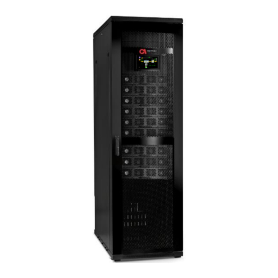
Page 20: Figure 1: B240 Model, Front View
Figure 1: B240 Model, Front View UPS for 480 Vac Grid, User Guide, doc. rel. 4.0... -
Page 21: Figure 2: Major Components
Figure 2: Major Components Figure 3: Connection Terminals (Rear View) Table 1: Key to Figure 2 ESCRIPTION Protective earth (ground) bus bar Midpoint terminal AC RECTIFIER INPUT terminals (L1, L2, L3) AC BYPASS INPUT terminals (L1, L2, L3) AC OUTPUT terminals (L1, L2, L3) BATTERY terminals (positive, negative) UPS for 480 Vac Grid, User Guide, doc. -
Page 22: Overview Of System Components
3. Overview of System Components This section provides a brief overview of the role and function of the UPS primary components. It includes the following sections: 1. System Controller (includes LCD control panel) 2. Ac power module (30 kVA / 30 kW) 3. -
Page 23: Dc Converter Module (60Kw)
3.3. Dc converter module (60kW) The dc-dc converter module converts the ± 240V dc from the battery bank to ±420V dc required by the inverter. The dc-dc converter module is also responsible for charging of the battery bank The dc-dc converter module is the key to the UPS's small battery footprint. The UPS supports up to four identical internal dc converter modules all operating in parallel. - Page 24 The UPS supports the use of standard lead-acid batteries. If you plan to use lithium-ion batteries you must supply your own BMS (Battery Management System), and you must follow Gamatronic special instructions for lithium-ion battery setup. Setup instructions are available from support@gamatronic.com UPS for 480 Vac Grid, User Guide, doc.
-
Page 25: Overview Of Operating Modes
4. Overview of Operating Modes The UPS functions to supply ac electrical power to your load. The UPS has five primary modes of operation: 1. Normal mode 2. Battery mode 3. Bypass mode 4. ECO mode 5. External Manual Bypass mode The following sections provide a short summary of the function and purpose of each mode. -
Page 26: External Manual Bypass Mode
standby state. Meanwhile, the rectifier continues to charge the dc converter that charges the battery during ECO Mode. When the UPS in ECO Mode detects an irregularity in the bypass input, the UPS transfers the load to the Inverter and feeds the load conditioned power. The advantage of operating a UPS in ECO Mode is that, in effect, the UPS operates as a stand-by UPS. -
Page 27: Manual) Emergency Power Off - Epo
5. (Manual) Emergency Power Off – EPO An external Emergency Power Off (EPO) switch may be installed on the UPS by the customer. The EPO switch is used to cut power to the load in emergency situations. The switch or push button must be a normally open type. -
Page 28: Restarting The Ups After Epo
5.3. Restarting the UPS after EPO After the emergency that prompted use of the EPO switch has been resolved, the UPS can be restarted as follows: 1. Reset the EPO switch. 2. Switch OFF the following circuit breakers: Ac input ... -
Page 29: Ups Lcd User Interface
6. UPS LCD User Interface The UPS control system provides the user complete control over the UPS and its operating parameters. This chapter describes the most important and frequently used functions. 6.1. System Menu (LCD home) screen The System Menu is the user's starting point for most operations. Figure 4: System Menu screen Figure 4 illustrates the System Menu while Table 2 explains System Menu features. -
Page 30: Table 2: Key To Figure 4
Table 2: Key to Figure 4 ESCRIPTION The operational status (ON/OFF) and current mode (Normal [inverter] mode / bypass mode / Battery mode / ECO Mode / Maintenance Bypass). Menu options. Pressing these eight icons give access to the main submenus. Alarm mute button. -
Page 31: System Menu Highlights
A navigation path is visible in the upper-left corner hand of the LCD screen. The navigation path can be used to navigate backwards to a previous menu or directly to the System Menu. You can also select any icons in the navigation path to navigate to the screen represented by that icon. -
Page 32: Status Menu
Status menu 6.2.2. Selecting the Status option from the System Menu, displays a diagram which summarizes the overall UPS state. Figure 6: System Menu, Status option The Status screen appears: Figure 7: System Menu, Status screen UPS for 480 Vac Grid, User Guide, doc. rel. 4.0... -
Page 33: Setup Menu
In Figure 7 notice the following: Indicator Meaning This symbol indicates the current power flow through the UPS. This symbol indicates an alarm condition related to the UPS component where the triangle is located. For a complete breakdown of options on the Status screen, refer to Section 8.4. -
Page 34: Time
For a complete description of all Setup menu functions, see Section 8.2. Time 6.2.3.1. Selecting the Time icon on the System Menu to see the system time, the time zone setting (relates to when daylight savings time goes into effect), and the accumulated operational time. Figure 9: Setup, Time option System date/time must be accurate in order to enable technician level access and ensure accuracy of system timestamps. -
Page 35: Profile Menu
When the specified alarm occurs, the contact closes. The output dry contacts can be used to trigger external devices. For detailed information about Dry Contacts, refer to Section 8.2.10. Profile menu 6.2.4. Selecting the Profile icon from the System Menu, lets you view various system parameters as defined by the factory or by your system technician. -
Page 36: Figure 12: System Menu, Log Option
Figure 12: System Menu, Log option Events listed include system power-up and power-down and the start and end of all alarm conditions. For detailed information about Log options, refer to Section 8.6. UPS for 480 Vac Grid, User Guide, doc. rel. 4.0... -
Page 37: Operating The Ups
6.3. Operating the UPS From the System Menu, the Operation option is used to perform the following operations: 1. Turn on UPS (System on) 2. Turn off UPS (System off) 3. Turn off power modules 4. Turn on power modules 5. -
Page 38: Turn Off Ups
Turn off UPS 6.3.2. Figure 14: Operation, Turn off UPS option Turn off power modules 6.3.3. Figure 15: Operation, Turn off power modules option This function can be used to just shut down the Inverter or completely shut down the power module. Turn on power modules 6.3.4. -
Page 39: Turn On Dc Modules
Turn on dc modules 6.3.5. Figure 17: Operation, Turn on dc modules option Turn off dc modules 6.3.6. Figure 18: Operation, Turn off dc modules option Transfer load to bypass 6.3.7. Figure 19: Operation, Transfer load to bypass option Transfer load to inverter 6.3.8. -
Page 40: Battery Test
Battery Test 6.3.9. Figure 21: Operation, Battery Test option Turn on ECO Mode 6.3.10. Figure 22: Operation, ECO Mode on option Turn off ECO Mode 6.3.11. Figure 23: Operation, ECO Mode off option UPS for 480 Vac Grid, User Guide, doc. rel. 4.0... -
Page 41: Ups Start-Up/Shutdown
7. UPS Start-up/Shutdown 7.1. Switch on UPS (not first-time start-up) This section explains the start-up procedures for the operator after a UPS shutdown. UPS shutdown could have occurred for any of the following reasons: Due to battery exhaustion following an extended power outage. ... - Page 42 The Load icon (bottom right hand corner of the screen) indicates that the UPS is not bearing a load. The Alarm icon is active because the UPS is in OFF mode, instead of normal operating mode. (not first time) To perform a UPS startup: 1.
-
Page 43: Ups Total Shutdown (No Ac Output)
7.2. UPS Total Shutdown (no ac output) To perform a total UPS shutdown (with no ac output): 1. Switch OFF the load device(s). 2. From the System Menu select Operation > Turn ON/OFF > System OFF. The System Menu screen appears: Figure 25: UPS is Off Notice the Status screen displays the status message UPS OFF, No output. -
Page 44: Ups Menu Functions
8. UPS Menu Functions The touch sensitive LCD control panel is the user's main interface with the UPS. Figure 26: LCD control panel, displays the System Menu The user navigates the system by lightly pressing different system icons. The current navigation path (i.e. breadcrumb) appears in the upper-left hand corner of all screens (see Figure 27), except the System Menu screen (see Figure 26) –... -
Page 45: Figure 28: Ups System Menu
Use the breadcrumb to check the path you have followed while navigating system control menus. System breadcrumb can also be used to navigate backwards (i.e. to return to a previous screen or to the System Menu). The LCD control panel is mounted on the front door of the UPS. The LCD control panel is active when the UPS is connected to ac power, or the UPS is operating in battery mode. -
Page 46: Password Requirements
8.1. Password Requirements As you navigate the user interface you will see certain menus items which are marked with a small Key-shaped icon (see Figure 29). Figure 29: Key icon on Multisystem mode The icon signifies a Gamatronic password key is required. After the key is used, the function is enabled for the UPS. -
Page 47: Setup > System
Figure 30: Setup menu All setup settings are available to be modified by Technician only. Setup > SYSTEM 8.2.1. The Setup > System submenu is used to update the UPS about its operating environment regarding the following parameters: Nominal input and output values of the UPS ... -
Page 48: Setup > System > Nominal Settings
Figure 31: Setup > SYSTEM menu hierarchy Controller > Controller menu options are only accessible after logging in at Technician level. System Type > ECO Mode, Self-loading mode, Battery mode are only accessible after logging in at Technician level. Setup >... -
Page 49: Setup > System > Number Of Modules
Before modifying the UPS nominal frequency, the UPS must be turned off by means of the ON/OFF button on the System Menu screen. Obviously, the nominal system frequency chosen should be the same as the nominal frequency of the rectifier input and bypass voltage. Frequency tracking range. -
Page 50: Redundancy
total output requirements of the power modules are adequately covered. If there are an odd number of power modules in the system, the extra dc converter block will insure evenly distributing the battery charging and discharging current throughout the system. 8.2.1.2.1. -
Page 51: Eco Mode
A Gamatronic key may be required to change this setting. If you do not have the appropriate Gamatronic key, contact your distributor or sales agent. 8.2.1.3.2. ECO Mode In ECO Mode (also known as offline), the load is powered from the bypass line. In the event of a problem with the bypass input, the load is transferred to the Inverter. -
Page 52: Setup > System > Controller
Use this option to specify the behavior of the UPS after a prolonged failure of the ac mains power. Figure 32: Shutdown and Auto-restart screen You can set a specific limit to the duration of battery mode, after which time the UPS will ... -
Page 53: Screen Saver Setup
8.2.1.5.4. Screen saver setup Enables/disables the LCD panel’s screen saver. 8.2.1.5.5. Celsius/Fahrenheit Select Celsius or Fahrenheit temperature scale for temperature measurements. Setup > System > MAINTENANCE 8.2.1.6. This option has several sub-options. Some are related to system maintenance and some to the system log. -
Page 54: Figure 33: Setup > Modules Menu Hierarchy
For complete instructions contact your service provider. The following sections are for technician use only and should only be performed by trained professionals familiar with the system. You should disable Auto Correction before making any changes covered in this Section. Figure 33: Setup >... -
Page 55: Power Module Ac Input Voltage Calibration
POWER MODULE AC INPUT VOLTAGE CALIBRATION 8.2.2.1. Use this function if it becomes necessary to recalibrate the voltage readings of any of the UPS's input phases. Keep in mind that this does not refer to the input reading of a module, but instead to input of all modules combined together. -
Page 56: Power Module Ac Output Voltage Calibration
Figure 35: AC Input Voltage Calibration 2. For each input phase use a voltmeter to measure between the phases (Line 1 = L1 to L2; Line2 = L2 to L3; Line 3 = L3 to L1). 3. Enter the measured values into the screen and select Confirm. This completes the ac input voltage calibration. -
Page 57: Power Module Input Current Calibration
Calibration should be performed only under conditions where the input voltages are stable and not subject to fluctuation. The system must be in normal mode to perform this calibration. 1. From the System Menu go to Modules > AC Output voltage calibration. The AC output voltage calibration screen appears: Figure 36: AC Output Voltage Calibration 2. - Page 58 An external load bank will be necessary in order to perform this calibration. The value you enter is sent to all modules, so input current calibration is best to be performed one module at a time, with all the other modules turned off. (To turn modules OFF, refer to Section 8.3.2.1.) Start from the bottom (most) module and work your way up.
-
Page 59: Power Module Output Current Calibration
Figure 37: Modules Input Current Calibration 2. Measure the current on the input phase with an ammeter. For your reference, the present UPS measured values are displayed on the right side of the screen. 3. Type the measured value into this screen and select Confirm. This completes module input current calibration. - Page 60 To turn modules OFF, refer to Section 8.3.2.1. Start from the bottom (most) module and work your way up. Modules output current calibration should be performed only if necessary, not casually. Modules output current calibration should be performed only under ...
-
Page 61: Power Module Dc Voltage Calibration
Figure 38: Modules Output Current Calibration screen 3. Measure the current of the output phase with an ammeter, then enter the measured value into this screen and select Confirm. When you select Confirm, only the values that you have modified (indicated by a change in color of the numbers from white to orange) are sent to the module. -
Page 62: Figure 39: Modules > Dc Voltage Calibration Screen
Auto Correction is enabled by default. This is the recommended setting for most situations. After performing any calibrations or adjustments the Auto Correction feature should be re-enabled, for optimal system performance. Figure 39: Modules > dc voltage calibration screen Each power module’s readings are calibrated before the UPS leaves the factory, but over time or due to environmental factors the UPS’s dc measurements may drift slightly. -
Page 63: Figure 40: Status > Modules, Pfc Status Tab, Dc Relay Is On
To perform power module dc voltage calibration: 1. Confirm that the UPS is operating in normal mode. 2. Verify all dc converter modules are all operational (you can check either through the Status screen or by checking that all dc converter module LED lights are green). Figure 40: Status >... -
Page 64: Ac Output Voltage Adjustment
Figure 41: Dc voltage calibration 10. Press the Confirm button to apply the corrected measurements. 11. Switch OFF the module just calibrated and switch ON the next module above it. 12. Perform steps 3 through 11 until all modules have been calibrated. AC OUTPUT VOLTAGE ADJUSTMENT 8.2.2.6. - Page 65 Each ac power module’s output voltage must be adjusted on its own. In order to adjust the output phases all other modules must be have their inverter off and the unit must be on normal mode. This may require the system to be placed in maintenance bypass. If the maintenance bypass breaker is connected to the UPS's manual bypass terminals, the connector will need to be disconnected after opening the UPS output CB.
-
Page 66: Figure 42: Output Terminals
Figure 42: Output terminals 7. Navigate to Setup > Modules > Ac output voltage adjustment. 8. The Output Voltage Adjustment screen appears. Figure 43: AC Output Voltage Calibration UPS for 480 Vac Grid, User Guide, doc. rel. 4.0... - Page 67 9. Measure the voltage between the L1 bus and midpoint bus bar. See Figure 42: Output terminals. You would expect the value to be around 277Vac, ± 3 V. 10. Compare your measured value to the nominal output voltage. 11. Adjust line 1 up or down accordingly to acquire the desired output voltage. 12.
-
Page 68: Dc Bus Voltage Calibration
DC BUS VOLTAGE CALIBRATION 8.2.2.7. Use this function is used to correct any inaccuracy in the UPS’s reading of the battery voltage. Auto Correction is enabled by default. This is the recommended setting for most situations. After performing any calibrations or adjustments the Auto Correction feature ... -
Page 69: Figure 45: Dc Bus Terminals
Figure 45: dc bus terminals To detect and correct any inaccuracy in the UPS’s display of the dc voltage: 1. Verify that all dc relays are ON. 2. Remove the back panel for the fuses exposing the positive, negative, and mid-point bus terminals. -
Page 70: Dc Voltage Adjustment
DC VOLTAGE ADJUSTMENT 8.2.2.8. Use this function is used to correct any inaccuracy in each module’s rectifier dc voltage. Each power module’s dc voltage are calibrated before the UPS leaves the factory, but over time or due to environmental factors the UPS’s dc voltage may drift slightly. -
Page 71: Figure 46: Dc Voltage Adjustment Screen
Figure 46: DC Voltage Adjustment screen Adjustment of the dc voltage should be performed only under conditions where the UPS's input currents and voltages are stable and not subject to fluctuation. The readings for the positive and negative components of the module’s dc voltage are calibrated separately (but on the same screen) and can be increased or decreased separately. -
Page 72: Serial Number
To disconnect all of the other modules from the system rack disconnect the PFC and inverter ribbon cables and slide the module out by at least 3 inches. 6. Wait for the UPS to transfer to Normal mode and charge the battery Main>status. If the power module does not automatically start pre-charge, select and manually turn on the module, main>operation>turn on/off>modules on. -
Page 73: Auto Corrrection
Figure 47: Serial Number screen The serial number can be found on a silver sticker on the exterior of each UPS power module. The serial number of each power module is set by default. Technicians should Only perform this in case of a module calibration reset. AUTO CORRRECTION 8.2.2.10. -
Page 74: Power Walk-In
Figure 48: Auto Correction screen Auto Correction is enabled by default. This is the recommended setting for most situations. After performing any calibrations or adjustments the Auto Correction feature should be re-enabled, for optimal system performance. POWER WALK-IN 8.2.2.11. -
Page 75: Setup > Dc/Dc
Figure 49: Power Walk-In screen The UPS gently raises the dc voltage, suppressing inrush current that would otherwise be experienced by the power input source. Setup > dc/dc 8.2.3. The Setup > dc-dc menu provides access to parameters related to the dc-to-dc conversion modules. -
Page 76: Battery Voltage Calibration
Figure 50: Setup > dc-to-dc options Figure 51: Setup, DC-to-DC Menus Battery voltage calibration 8.2.3.1. This function is used to correct any inaccuracy in the UPS's reading of the battery voltage. The UPS’s readings are calibrated before the UPS leaves the factory, but over time or due to environmental factors the UPS’s dc measurements may drift slightly. -
Page 77: Figure 52: Battery Bus Bars And Midpoint Bus Bar
calibrated, the battery voltage reading would be displayed as 270 Vdc negative and 270 Vdc positive. To detect and correct any inaccuracy in the UPS’s display of the battery voltage: 1. Measure the actual battery voltage with a calibrated voltmeter. There are labeled battery dc bus bars inside the UPS. -
Page 78: Dc Voltage Calibration
Figure 53: Battery Voltage Calibration screen 2. Compare your measured value to the number to the right of the screen (Figure 53), which is the UPS’s measurement. 3. If the value you measured differs from the UPS’s measured value, enter your measured value into the field labeled Battery negative dc voltage (Figure 53). -
Page 79: Figure 54: Dc-Dc Blocks Numbering Sequence
In the dc calibration screen found in Figure 56 the UPS displays the dc voltage in two parts: a negative half and a positive half. For example, if the UPS load was perfectly stable and the UPS’s measurement was perfectly calibrated, the dc voltage reading would be displayed as 435 Vdc negative and 435 Vdc positive. -
Page 80: Figure 55: Dc Buses
Figure 55: dc Buses 3. Compare your measured value to the number to the right of the screen (see Figure 56), which is the UPS’s measurement. If your measured value differs from the UPS’s measured value, enter your measured value into the field labeled Negative dc voltage. 4. -
Page 81: Charger Current Calibration
The corrected measurements are applied. 6. Repeat the process for each dc-dc block, one block at a time, turning off all the dc blocks except the one being calibrated. Charger current calibration 8.2.3.3. Use this function if it necessary to recalibrate the ampere readings of one of the UPS's input phases. -
Page 82: Dc-To-Dc Voltage Adjustments
6. Press Confirm to apply the corrected measurements. 7. Switch off the dc block you just calibrated and switch on the next-highest block (see the sequence numbers in Figure 57. 8. Repeat steps 3 through 7 until all the dc-dc blocks have been calibrated. Figure 57: Charger current calibration screen Dc-to-dc voltage adjustments 8.2.3.4. -
Page 83: Adjusting The Battery Voltage (The "Buck" Voltage)
Figure 59: Boost Current Calibration The ideal boost voltages are ± 425 Vdc. The voltages can be adjusted up or down by up to 1.875 volts. Modification of the boost voltage should be done when there is no load on the UPS, and no ac input –... -
Page 84: Serial Numbers
Modification of the battery voltages should be made only when the battery is fully charged. Serial Numbers 8.2.3.7. Use this function to record the serial numbers of the UPS’s modules. Figure 60: Serial Numbers The serial number can be found on a silver sticker on the exterior of each UPS module. -
Page 85: Setup > Battery
Setup > BATTERY 8.2.4. For complete instructions contact your service provider. The following sections are for technician use only and should only be performed by trained professionals familiar with the system. Setup > BATTERY functions provide control over several battery parameters. Figure 61: Setup, Battery menu options The UPS supports the use of standard lead-acid batteries, and lithium-ion batteries. -
Page 86: Setup > Battery > Battery Test Parameters
Figure 62: Setup > Battery menu hierarchy Setup > Battery > BATTERY TEST PARAMETERS 8.2.4.1. The parameters in this section relate to the battery test function. Figure 63: Battery, Battery Test Menu options UPS for 480 Vac Grid, User Guide, doc. rel. 4.0... -
Page 87: Battery Test Fault Voltage
8.2.4.1.1. Battery test fault voltage During the automatic scheduled battery test the dc voltage will try to drop to 235 Vdc (11.75 x 20 batteries per poll). If the batteries are unable to hold the minimum charge the battery test will fail due to one of the batteries having a lower voltage than 11.75 V dc. -
Page 88: Automatic Battery Test Interval
Figure 65: Rectifier voltage at Battery Test Do not change the default setting. 8.2.4.1.3. Automatic battery test interval The UPS conducts a periodic battery test automatically according to the time interval specified here. Figure 66: Automatic Battery Test Period The time interval is specified in weeks. UPS for 480 Vac Grid, User Guide, doc. -
Page 89: Factors That Can Delay The Automatic Battery Test
8.2.4.1.3.1. Factors that can delay the automatic battery test If the UPS’s ac input voltage is high, the battery test is postponed until the UPS’s input voltage becomes lower. A “high” input voltage in this case means “greater than the battery test voltage divided by √2”. -
Page 90: Enable/Disable Current Sensors
Figure 68: Setup, Battery, Battery Current 8.2.4.2.1. Enable/Disable current sensors Use this function to enable or disable external battery current sensors. Figure 69: Enable/Disable Current Sensors 8.2.4.2.2. Calibrate battery current This function is used to calibrate battery current reading for any of the battery strings. The Set dc current offset and Calibrate battery current functions should be performed only if the battery current measurement is not correct. -
Page 91: Set Dc Current Offset
To calibrate battery current: 1. Operate the UPS without a load and with batteries disconnected. 2. Perform the Set dc current offset function (only if the measured current is not zero). 3. Connect the UPS to its batteries and to a load and operate the UPS in battery mode. Figure 70: Calibrate Current 4. -
Page 92: Set Battery Current Limit Value
Figure 71: Set dc current offset The Set dc current offset and Calibrate battery current functions should be performed only if the battery current measurement is not correct. They are generally used only when current sensors are added to the system. To set dc current offset: 1. -
Page 93: Minimum Dc Voltage At Current Limit
Figure 72: Battery Current Limit Value There are two options: Set maximum battery current to 0.1 x battery capacity. Set maximum battery current to 0.2 x battery capacity. 8.2.4.2.5. Minimum dc voltage at current limit Use this function to set a minimum value for the battery-charging voltage when current limiting is in effect. -
Page 94: Setup > Battery End-Of-Backup Voltage Limit
Figure 73: Minimum dc voltage at current value The factory setting of 400 Vdc is recommended for most situations. Setup > Battery End-of-Backup voltage limit 8.2.4.3. During a mains power blackout, the batteries provide power to the UPS’s Inverter. In the process, the battery voltage continually decreases. -
Page 95: Setup > Battery > Battery Capacity In Ah
Figure 74: Setup, Battery End of backup voltage limit This function enables you to define the battery voltage at which the UPS will cease to provide backup power and will shut itself down. This helps avoid overly deep battery discharge, which shortens battery life. -
Page 96: Setup > Battery > Battery Temperature Control
Figure 75: Battery, Battery capacity This total battery capacity figure is used by the UPS in three ways: 1. To provide an estimate of the remaining battery time, when the system is in battery mode. 2. To calculate the battery current limit. 3. -
Page 97: Figure 76: Battery, Battery Temperature Control
Figure 76: Battery, Battery Temperature Control The Battery temperature control screen contains the following fields: Temperature sensors not installed. Indicate whether battery temperature sensors are present or not. Battery temperature sensors are required if one wishes to make use of battery temperature compensation (See Figure 76). -
Page 98: Lvd Battery Protector
The Temperature Compensation Parameters screen appears: Figure 77: Battery, Temperature compensation parameters 3. Adjust the temperature compensation factor for a single cell by changing the Temperature compensation factor for a single cell slider. The compensation factor is usually provided on the battery manufacturer's data sheet. 4. -
Page 99: Figure 78: Lvd Battery Protector
Although the battery is disconnected from the load, there is still a small voltage drain on the battery from other sources. If this drain continues for a long period of time it can result in a deep discharge of the battery, which shortens battery life. To protect the battery from deep discharge, the LVD function (Low Voltage Disconnect) enables the user to define a time interval after which the battery disconnects completely from all drainage sources. -
Page 100: Figure 79: Lvd Battery Protector
Figure 79: LVD Battery Protector Use the LVD screen to enable or disable the LVD function. When enabled, the battery disconnect takes place after the time interval (in hours) specified in the LVD screen. Any one of the eight output dry contacts can be used to signal that the LVD countdown is in progress. -
Page 101: Setup > Static Switch
Setup > STATIC SWITCH 8.2.5. For complete instructions contact your service provider. The following sections are for technician use only and should only be performed by trained professionals familiar with the system. Figure 80: Static Switch Menu options UPS for 480 Vac Grid, User Guide, doc. rel.4.0... -
Page 102: Setup > Stsw > Calibrate Bypass Voltage
Figure 81: Setup > Static Switch options Setup > STSW > CALIBRATE BYPASS VOLTAGE 8.2.5.1. For calibration of the bypass voltage reading (by phase). Figure 82: Static Switch, Bypass Voltage Calibration UPS for 480 Vac Grid, User Guide, doc. rel. 4.0... -
Page 103: Setup > Stsw > Calibrate Output Voltage
This voltage is a phase to ground reading. Setup > STSW > CALIBRATE OUTPUT VOLTAGE 8.2.5.2. For calibration of the ac output voltage reading (by phase). Figure 83: Static Switch, Output Voltage This voltage is a phase to ground reading. Setup >... -
Page 104: Figure 84: Static Switch, Enable Output Current
Figure 84: Static Switch, Enable Output Current Static Switch output current calibration should be performed only if necessary (not casually). Static Switch output current calibration should be performed only under conditions where the system input and output currents are stable and not subject to fluctuation. -
Page 105: Setup > Stsw > High-Level Setup
Setup > STSW > HIGH-LEVEL SETUP 8.2.5.4. These functions are related to the Static Switch. Figure 85: Setup > STSW > High-level setup Static Switch parameters should not be changed unless necessary. 8.2.5.4.1. Setup > STSW > Hi-level setup > BYPASS FORCED/CONTROLLED When the UPS wants to move to bypass mode, this function determines whether the controller will check the quality of the bypass voltage or not, before moving to bypass. -
Page 106: Setup > Stsw > Hi-Level Setup > Stsw Integration Time
8.2.5.4.2. Setup > STSW > Hi-level setup > STSW INTEGRATION TIME This option controls the amount of time the Static Switch waits before transferring the load to bypass after detecting that the Inverter output voltage is out of range. The "normal" setting is 3 ms, the "extended"... -
Page 107: Setup > Stsw > System Type
Figure 87: Static Switch, Enable/Disable Analysis Event This log information can be used by a technician when troubleshooting. Setup > STSW > System type 8.2.5.7. Informs the Static Switch of the system type in which it is installed, in terms of maximum output power, e.g. -
Page 108: Setup > Alarms
Static Switch system type should not be changed. Setup > ALARMS 8.2.6. For complete instructions contact your service provider. The following sections are for technician use only and should only be performed by trained professionals familiar with the system. Figure 89: Setup, Alarms menu options UPS for 480 Vac Grid, User Guide, doc. -
Page 109: Setup > Alarms > Set Alarm Priorities
Figure 90: Setup > Alarms options Setup > Alarms > SET ALARM PRIORITIES 8.2.6.1. This function enables you to assign one of three possible levels of importance to each type of system alarm. The levels of importance, in ascending order of importance, are Information, Warning, and Critical. -
Page 110: Figure 91: Alarms > Alarm Limits
Figure 91: Alarms > Alarm Limits UPS for 480 Vac Grid, User Guide, doc. rel. 4.0... -
Page 111: Setup > Alarms > Alarm Limits > Dc Voltage Limits
8.2.6.2.1. Setup > Alarms > Alarm Limits > dc VOLTAGE LIMITS Use this function to set the voltage levels at which the dc VOLTAGE HIGH and dc VOLTAGE LOW will be activated. Figure 92: Alarms limit > dc voltage limit configuration These parameters should not be changed. -
Page 112: Setup > Alarms > Alarm Limits > Battery Low Limit (Per Battery)
Figure 93: Alarm limits > ac voltage configuration These parameters should not be changed. You can also set a "hysteresis" value. This value damps the sensitivity of the alarms to prevent a situation where, for example, a minor but frequent fluctuation of 1 Vac just above or below the threshold value causes an ac voltage alarm to turn on and off many times, rapidly. -
Page 113: Setup > Alarms > Alarm Limits >Temperature Limits
Figure 94: Alarms limit > Battery low limit voltage 8.2.6.2.4. Setup > Alarms > Alarm Limits >TEMPERATURE LIMITS This function lets you set the temperature (in °C) at which the high-temperature alarm and low- temperature alarm are generated. The temperature is read from an optional internal temperature sensor. -
Page 114: Setup > Alarms > Alarms Configuration
Figure 95: Alarms limit > temperature configuration Setup > Alarms > ALARMS CONFIGURATION 8.2.6.3. This function allows you to adjust each of the system alarm warning sensitivity levels. All system alarms by default are added to the log. These parameters should not be changed. If you want to restore all alarms to default alarm system sensitivity settings, select the Restore Factory Settings button and then Save. -
Page 115: Setup > Connectivity
To change default alarm settings: Figure 96: Setup, Alarms > Alarms Configuration, Restore Factory Settings By selecting the Left and Right arrow at the top of the screen, you can navigate through each of the system Alarms and modify its default settings. If you select the Ignore checkbox, the selected alarm will be ignored all together. -
Page 116: Optional) Setup > Connectivity > Network Configuration
Figure 97: Setup > Connectivity options (Optional) Setup > CONNECTIVITY > NETWORK CONFIGURATION 8.2.7.1. The UPS can be monitored from a distance over an intranet or the Internet, through the same menus and screens used on the UPS control panel. This feature is compatible with Windows, Windows NT, and Linux ... -
Page 117: Network Configuration Options
3. Connect the UPS to the local Ethernet network using the Ethernet (RJ45) port on the rear panel of the UPS controller. This is the port labeled “SNMP” on the controller rear panel. 4. On a computer terminal that has connectivity to the UPS IP address, open a Web browser and enter the UPS IP address in the URL bar. -
Page 118: Figure 98: Setup > Connectivity > Snmp Configuration Options
The SNMP screen appears: Figure 98: Setup > Connectivity > SNMP configuration options 2. Select Add new community…: The NEW SNMP community screen appears: Figure 99: Creating a new community 3. Type in the desired community name in the Community name text input field and select the appropriate community rights from the Community rights radio button. -
Page 119: Snmp Configuration > Accept Snmp Packets From These Hosts
The SNMP screen appears: Figure 100: Community name accepted To delete a community: 1. Select the community name to be deleted. A screen appears. 2. Select Delete (at the bottom of the screen). The community is deleted. 8.2.7.3.2. SNMP configuration > ACCEPT SNMP PACKETS FROM THESE HOSTS Selecting this check box allows SNMP packets to be accepted from any host. -
Page 120: Snmp Configuration > Trap Destinations
8.2.7.3.3. SNMP configuration > TRAP DESTINATIONS An SNMP trap is a destination to which the UPS will send alarm notifications using the SNMP protocol. For each destination, an IP address and a port must be specified. Adding or deleting trap destinations is performed in the same manner as adding or deleting communities. -
Page 121: Optional Feature) Modbus
If the serial communication option is ordered as an add-on to an existing system, the physical connection details may be different than described above. (Optional feature) Modbus 8.2.7.5. The ability to use a Modbus link with the UPS is an optional feature, available by special order. A password may be required to use this feature. -
Page 122: Optional Feature) Email Configuration
The Modbus Configuration screen appears: Figure 102: Defining Modbus communication parameters 2. Select a Protocol (RTU or ASCII) and a Baud rate, as recommended by your Modbus network administrator, and select the Allow serial Modbus checkbox to enable it. The UPS's physical connection for serial Modbus is a 4-pin connector (P5) located in “connector group 2”... -
Page 123: Figure 103: Example Of Email Message Body
A timestamp The user-assigned priority of the message (Informational / Warning / Critical) The main message text as it appears in the log The status of the log message: “On” (alarm condition started) or “Off” (alarm condition ended) ... -
Page 124: Table 3: Description Of Email Parameters
Table 3: Description of email parameters PARAMETER DESCRIPTION NAME Host name or IP, and port: MAIL SERVER Consult your network administrator for the name of your email server or its IP address, and for the proper port number to use. Enable email notifications: Mark the checkbox to enable email notification. -
Page 125: Adding A New Email Recipient
8.2.7.6.1. Adding a new email recipient To add a new email recipient: 1. Selecting the Email recipients button brings up a list of the existing recipients and the opportunity to add a new recipient. The Email Recipients screen appears: Figure 105: Email Recipients screen 2. -
Page 126: Figure 107: Alarms Button On Email Recipient Screen
8. If you select the Send button, a test email is sent to the new recipient, to verify that that the email has been created successfully. Figure 107: Alarms button on email recipient screen 9. After the recipient has been created, the Alarms button in the lower left of the screen becomes active. -
Page 127: Controller Host Name
Controller host name 8.2.7.7. Use this option to specify a name for the controller. The network manager will see this name. In the event of any network-related problems he will be able to identify the device in question. This is especially useful when there is more than one UPS connected to the network. If you give each UPS a unique name, the network manager will be able to distinguish between them. -
Page 128: Set Date And Time
Figure 110: Setup, Time options Set date and time 8.2.8.1. Enter the year, month, day, hour, minute, and second. Setup > Time > ADJUST DATE / TIME 8.2.8.2. To set date/time: 1. Modify any or all the date/time fields as required (year, month, day, hours, minutes, and seconds). -
Page 129: Setup > Time > Change Time Zone
Setup > Time > CHANGE TIME ZONE 8.2.8.3. Use this function to set the UPS to the proper time zone. Setup > Time > Time Synchronization 8.2.8.4. This will only work when connected to a network. Figure 112: Setup, Time, Time Synchronization Setup >... -
Page 130: Figure 113: Setup > Assign Site Id
The system password is required to change the site ID and should not be changed. This function enables descriptive text to be associated with the unit. Figure 113: Setup > Assign Site ID When the UPS is connected to a computer network, this information can be seen by someone who is monitoring the UPSs via an SNMP program. -
Page 131: Figure 114: Assigning A Site Id
Figure 114: Assigning a site ID For the authorization level of User, the descriptors are shown in Figure 114. Click on a field to display the virtual keyboard which you can use to enter the descriptive information. UPS for 480 Vac Grid, User Guide, doc. rel.4.0... -
Page 132: Optional Feature) Setup > Dry Contacts
(Optional feature) Setup > DRY CONTACTS 8.2.10. This function enables the user to manage the UPS's input and output dry contacts. Figure 115: Setup > Dry Contacts menu A password may be required to use functions available in this menu. If you do not have the appropriate password it can be obtained from the Gamatronic customer support team. -
Page 133: Setup > Dry Contacts > Input Dry Contacts
Setup > Dry contacts > INPUT DRY CONTACTS 8.2.10.1. The input dry contacts enable the user to monitor the state (open or closed) of a relay external to the UPS, by generating an alarm condition when the state of the external relay changes. (The relay must be voltage free. -
Page 134: Figure 117: Defining An Input Dry Contact
Figure 117: Defining an input dry contact The user must also ensure that the input dry contact is enabled, by selecting the Enabled checkbox for that dry contact in the same screen (see Figure 117). An alarm has been pre-assigned to each of the input dry contacts. (You can see these alarms in the Setup >... -
Page 135: Setup > Dry Contacts > Output Dry Contacts
Setup > Dry contacts > OUTPUT DRY CONTACTS 8.2.10.2. Figure 118: Setup > Output Dry Contacts There are eight output dry contacts There are currently 48 alarm conditions to which the output dry contacts can be linked, so that when the alarm condition occurs, the state of the output dry contact will change. - Page 136 Extension Board communication failed Invalid Controller software Invalid network card More than one module is sending an alarm or warning Static switch is sending alarm or warning Load is now running on bypass Temperature fault No AC output to load DC voltage high DC voltage low End of battery backup, battery discharged to shut down limit...
-
Page 137: Figure 119: Example Of An Output Dry Contact Linked To An Alarm
DC/DC blocks are operating in mixed mode Battery temperature fault Voltage compensation is on Actual responding DC/DC blocks less than defined Neutral Wiring Fault More than one DC/DC blocks are sending an alarm or warning No DC/DC blocks are responding LVD protector activated LVD tripped Overload current on low voltage... -
Page 138: Location Of The Output Dry Contacts
8.2.10.2.1. Location of the output dry contacts The connections for the output dry contacts are in “Connector group 2” on the front panel of the UPS. (See Figure 1) The connections are on plugs P1 through P4 (and are named “digital output #1”... -
Page 139: Setup > Save And Restore
Figure 120: Generator Mode Setup screen Setup > SAVE and RESTORE 8.2.11. This set of functions let you save the current UPS settings and restore them later. Figure 121: Setup > Save & Restore options This would enable you to experiment with new settings and then easily return to the previous settings. -
Page 140: Setup > Save & Restore > Restore Settings
Setup > Save & restore > RESTORE SETTINGS 8.2.11.2. Restores to active status the settings that you previously saved in non-volatile memory. Setup > Save & restore > RESTORE FACTORY SETTINGS 8.2.11.3. Restores to active status the factory default settings of the UPS. Performing this function does not have any effect on what is saved by the SAVE SETTINGS function (above). -
Page 141: Setup > Authorization
Setup > AUTHORIZATION 8.2.12. Figure 122: Setup, Authorization System time/date must be correct in order to enable Technician level access. This function allows you to switch to a different user level. Figure 123: Setup > Authorization option UPS for 480 Vac Grid, User Guide, doc. rel.4.0... -
Page 142: Setup > Authorization > Set User Authorization Level
Setup > Authorization > SET USER AUTHORIZATION LEVEL 8.2.12.1. The UPS provides three user roles: User Technician Super-User Technician and Super-User roles are granted access to additional capabilities and menu functionalities. This additional functionality/capability is hidden from User level. -
Page 143: Operation Menu
8.3. OPERATION menu Figure 125: System Menu > Operation menu hierarchy tree Figure 126: Operation Menu UPS for 480 Vac Grid, User Guide, doc. rel.4.0... -
Page 144: Operation > Turn On/Off > System On/Off
Static Switch Snapshot and Self-loading mode Setup functions are reserved for Technician use only. ECO Mode is available by special order. Operation > Turn On/Off > SYSTEM ON/OFF 8.3.1. This section explains how to turn the UPS on/off. Operation > Turn on/off > SYSTEM ON 8.3.1.1. -
Page 145: Operation > Switch On/Off > System Off
Figure 127: Turn off/on menu Pressing the ON/OFF button on the System Menu also brings you to this (Operation > Turn on/off) screen (as shown above). 3. Select System On. The This action will turn all the modules on, confirm dialog appears: Figure 128: Confirm dialog, Turn all modules on 4. -
Page 146: Operation > Turn On/Off > Modules On/Off
1. From the System Menu select Operation > Turn on/off. The Turn on/off screen appears: Figure 129: Turn off/on menu 2. Select System Off. The Turning the system off will disconnect the load confirm dialog appears. 3. Select OK. The UPS is turned off. Operation >... -
Page 147: Operation > Switch On/Off > Modules On
To turn power modules off: 1. From the System Menu select Operation > Turn on/off > Modules Off. The following screen appears: Figure 130: Turn On/Off, Modules Off 2. Select the desired power modules from the Power Modules you want to turn off. The selected power modules are highlighted in blue. -
Page 148: Operation > Turn On/Off > Controller Restart/Shutdown
This function reverses a power MODULES OFF command. To turn modules on: 1. From the System Menu select Operation > Turn on/off > Modules On. The following screen appears: Figure 131: Turn On/Off, Modules On 2. Select the desired power modules you want to turn on. The selected power modules are highlighted (in blue). -
Page 149: Operation > Turn On/Off > Controller Restart
Operation > Turn on/off > CONTROLLER RESTART 8.3.3.1. Use this function to restart the controller. The load is unaffected. Figure 132: Switch On/Off - Controller Restart The controller is restarted. Operation > Turn on/off > CONTROLLER SHUTDOWN 8.3.3.2. Use this function to shut down the controller. The load is unaffected. -
Page 150: Figure 133: Switch On/Off - Controller Shutdown
Figure 133: Switch On/Off - Controller Shutdown To reset the System Controller there is a recessed Reset button available on the back of the controller panel (adjacent to the USB ports). Figure 134: Controller Reset Button on the Back of the Controller UPS for 480 Vac Grid, User Guide, doc. -
Page 151: Operation > Transfer Load
Operation > TRANSFER LOAD 8.3.4. From this menu you can move the load from the Inverter to the bypass voltage, or vice versa. Operation > Transfer load > TRANSFER LOAD TO INVERTER 8.3.4.1. The Transfer load to inverter and the Transfer load to bypass buttons will be grayed out if the bypass and the inverter are not synchronized. -
Page 152: Operation > Transfer Load > Transfer Load To Bypass
Operation > Transfer load > TRANSFER LOAD TO BYPASS 8.3.4.2. Use this function to transfer the load from the Inverter voltage to the Bypass voltage. Figure 136: Operation, Transfer load to Bypass During normal operation, the load is supplied with power from the Inverter. The inverter voltage is controlled and regulated to protect the load from any aberrations in the local ac power. -
Page 153: Operation > Battery Test
Transfer to bypass can also be accomplished manually. To transfer the load from Inverter voltage to bypass voltage: 1. From the System Menu, select Operation > Transfer load > Transfer load to bypass. The Transfer load to Bypass confirm dialog appears: Figure 137: Transfer load to bypass 2. -
Page 154: Operation > Turn Eco Mode On/Off
Figure 138: Operation, Battery Test Operational parameters for the battery test can be found in Section 8.2.4.1. Operation > TURN ECO MODE ON/OFF 8.3.6. ECO Mode is an alternative mode of UPS operation. This section explains how to: 1) enable ECO mode, and 2) transfer the UPS to ECO mode. -
Page 155: Figure 139: Eco Mode Screen
charging the UPS batteries. In a typical UPS in ECO Mode this can provide a cost savings of 2 or 3 percent of power consumption. The downside is that the load can be directly exposed to the mains power for fractions of a second, without the power conditioning provided by the rectifier and the Inverter. - Page 156 If you don't intend to use Analyze Grid mode, the Custom Reliability settings take on the meaning of how long (relative to one another) the UPS will wait before returning the load to bypass mode. The more disruptions that occur with mains power, the lower its reliability and the longer the UPS will wait before returning the load to bypass.
-
Page 157: Figure 140: Eco Mode Screen
Figure 140: ECO Mode screen 3. From the ECO Mode screen, select Enabled. 4. Select Analyze Grid. In Analyze Grid mode, the UPS observes the bypass input for about a week and uses this information to determine which ECO Mode Custom Reliability setting is most appropriate for your environment. -
Page 158: Figure 141: Reliability Timeouts Screen
The Define Timeouts screen appears: Figure 141: Reliability Timeouts screen This screen allows you to customize the time to transfer back to ECO Mode from Inverter after an anomaly in the grid. 6. Customize the settings in the Define Timeouts screen according to the selected customized reliability setting you chose in the ECO mode screen. -
Page 159: Figure 142: System, System Type Screen
The System Type screen appears: Figure 142: System, System Type screen You have successfully enabled analyze grid as well as customized reliability timeout settings. The next step is to transfer the UPS to ECO Mode. To transfer the UPS to ECO Mode: 1. -
Page 160: Figure 144: Ups Is On, Eco Mode Is Turned On And Inverter Is In Standby State
Notice the Status screen when the UPS is ON, but it is in normal mode. This is prior to ECO Mode being turned on. 2. From the System Menu select Operation > ECO Mode and ensure ECO Mode is toggled on. Next confirm ECO Mode is turned on. -
Page 161: Operation > Firmware Update
Figure 145: UPS is ON, UPS is on and ECO Mode/Inverter is in active state Notice the yellow line (representing the direction of power to the load) is passing through the Inverter while ECO Mode is not running. Operation > Firmware Update 8.3.7. -
Page 162: Figure 146: Required System Off Warning
Figure 146: Required system off warning 2. Select OK to continue The following system and subsystem selection screen appears: Figure 147: Select unit for update 3. Select from one of the subsystems to upgrade exclusively. If you intend on updating all of the subsystems you can do so by selecting System. -
Page 163: Figure 148: Insert Usb Screen
Figure 148: Insert USB screen The USB drive can be inserted into any of the three available USB slots located on the side of the system controller. Figure 149: USB port locations 4. Insert the USB with preloaded software in the root folder. UPS for 480 Vac Grid, User Guide, doc. -
Page 164: Figure 150: Inverter Update Screen
To update the full system: Select System, see Figure 147. Press start to begin the firmware upgrade process. Wait as the system runs through the various subsystems and upgrades each with the relevant firmware. To update the static switch only: Select STSW, see Figure 147. -
Page 165: Operation > Calibration Reset
Note that they are positioned in the same numbering layout as their physical position in the rack. Figure 151: PFC update screen Press start to begin the firmware upgrade process. If you would like to update DC/DC blocks only: Select the DC/DC block(s) you would like to update Note that they are positioned in the same numbering layout as their physical position in the rack. -
Page 166: Figure 153: System Off Warning
The system will need to be placed into maintenance bypass to perform firmware updated. The calibration reset will return all calibrations back to the factory default settings and the effected subsystems may require recalibrating to fit the site requirements. To perform a calibration reset: 1. -
Page 167: Figure 155: Inverter Calibration Reset Screen
To reset the calibrations of the inverter(s) only: Select the Inverter(s) you would like to reset Note that they are positioned in the same numbering layout as their physical position in the rack. Figure 155: Inverter calibration reset screen Once you press on the inverter icon the inverter will revert to factory default settings To reset the calibrations of the PFCs only: Select the PFC(s) you would like to reset Note that they are positioned in the same numbering layout as their physical position in the rack. -
Page 168: Figure 156: Pfc Calibration Reset Screen
Figure 156: PFC calibration reset screen Once you press on the PFC icon the PFC will revert to factory default settings To reset the calibrations of the DC/DC blocks only: Select the DC/DC block(s) you would like to reset Note that they are positioned in the same numbering layout as their physical position in the rack. Figure 157: DC/DC calibration reset screen Once you press on the DC/DC block icon the DC/DC block will revert to factory default settings UPS for 480 Vac Grid, User Guide, doc. -
Page 169: Status Menu
8.4. STATUS menu The Status screen summarizes the UPS current state. Figure 158: System Menu > Status option To view the UPS Status: 1. From the System Menu select Status. The Status screen appears: Figure 159: The Status Screen UPS for 480 Vac Grid, User Guide, doc. rel.4.0... -
Page 170: Table 5: Key To Figure 159 (The Status Screen)
In the diagram, shown in Figure 159, the highlighted yellow line indicates the present power flow through the UPS. A yellow triangle with an exclamation point inside indicates an Alarm condition related to the UPS component at the point where the triangle is located. Clicking on the component will provide more detailed information about the problem. - Page 171 ESCRIPTION Navigation trail – shows how you arrived at this screen. Voltage and amperage reading of each bypass input phase. Pressing the bypass input icon displays additional measurements for each bypass input phases. UPS state (ON / OFF) and mode (Normal [inverter] mode / Bypass mode / Battery mode / No output). Load level, indicates the load on each output phases, as a percentage of maximum capacity.
- Page 172 ESCRIPTION This graphic is displayed when the output source is the Inverter (normal mode, battery mode and inverter): This graphic is displayed when the output source is the bypass input (bypass or ECO Mode): This graphic is displayed when using Self-loading mode Pressing the Static Switch icon displays the Static Switch detail screen.
-
Page 173: Profile Menu
8.5. PROFILE menu From the System Menu selecting the Profile function displays a summary of the operating parameters of various parts of the system. Figure 160: System Menu > Profile options Profile > SYSTEM 8.5.1. Figure 161: Profile, System Lists the current values for a number of basic system settings, including: Nominal power Number or battery cabinets ... -
Page 174: Profile > Battery
Nominal ac voltage Automatic restart (enabled/disabled) Nominal frequency Shutdown by long ac fail (enabled/disabled) Number of modules Last maintenance date Number of DCDC blocks Model type Number of modules for redundancy Multi system mode ... -
Page 175: Profile > Stsw
Battery low limit voltage Current limit values (in amps) Rectifier voltage at battery test Battery cabinet capacities (in Ah) End-of-backup battery voltage limit Temperature sensor status (active/inactive) Automatic battery test period (in Temperature compensation status (active/inactive) ... -
Page 176: Profile > Alarms
Bypass (Forced/Controlled) Integration time (Regular/Extended) Voltage range (Narrow/Wide) Additional Static Switch information can be found in Section 8.2.5. Profile > ALARMS 8.5.4. Lists current parameter values, mostly alarm limit values, for alarms, including: Dc voltage high limit ... -
Page 177: Profile > Identification
Profile > IDENTIFICATION 8.5.5. Figure 164: Profile, Identification Lists several identifiers: Manufacturer Location Model name Attached devices Software version Module#1 System serial number Module #n Identification DC block #1 Contact name DC block #n ... -
Page 178: Log Menu
8.6. LOG menu From the System Menu selecting the Log function displays the log file. Figure 165: System Menu, Log options The log file display screen includes a button that you can press to clear the log file if you so desire. -
Page 179: Figure 166: Log File Contents Listing
In certain unusual cases, the user may want to change the severity level of a given message. This can be accomplished through the Setup > Alarms > Alarm configuration screen. Figure 166 (below) presents an example of a log file listing: Figure 166: Log file contents listing The full log can be exported to a USB drive for analysis. -
Page 180: Figure 167: Log Record - Detailed Display
The log error message details screen (Figure 167) appears: Figure 167: Log record - detailed display Figure 167 buttons at the bottom of the screen allow you to drill down to readings of specific system components, such as: the battery, the output stage, the bypass input, and so on, including individual modules. -
Page 181: Alarms Button On The Log Detail Screen
Alarms button on the Log Detail Screen 8.6.1. Figure 168 (second row of buttons at the bottom of the screen), Alarm button can be seen. Figure 168: Alarms display, from the Log detail screen Selecting this button displays a list of all alarms that were active at the time the log record was viewed. -
Page 182: Connectivity Menu
8.7. CONNECTIVITY menu From the System Menu the Connectivity function displays the status of the UPS's connection to the computer network, the UPS's IP address, and related information. This is of relevance if you are using the remote access feature, which enables monitoring and control of the UPS from a remote computer over an intranet or the Internet. -
Page 183: Language Menu
Figure 171: System Menu > Time option Figure 172: Time function on the System Menu 8.9. LANGUAGE menu From the System Menu the Language function gives you the ability to choose the language in which the display screen option and messages are displayed. Figure 173: System Menu >... -
Page 184: Periodic Preventative Maintenance
9. Periodic Preventative Maintenance The UPS should be inspected on a regular basis by a trained and qualified technician to verify that the UPS and batteries are in proper electrical and physical condition. A procedure for periodic preventive maintenance can be found in the UPS Installation Guide. It is recommended that this inspection procedure be performed every three to six months or in any case at least once annually. - Page 185 DURING MAINTENANCE ACTIVITIES SAFETY PROCEDURES MUST BE STRICTLY OBSERVED AT ALL TIMES This includes: Personal protection safety equipment such as rubber mats, rubber gloves, and eye protectors must be used at all times. All tools and equipment must be insulated against the ac and dc voltages and currents likely ...
- Page 186 Without proper maintenance, under certain conditions excessive amounts of hydrogen may be emitted from some batteries in the string when charging takes place. This can result in a dangerous accumulation of hydrogen, which, in turn, could result in a fire or explosion. UPS for 480 Vac Grid, User Guide, doc.
-
Page 187: Appendix) Holding Registers For Modbus Queries
10. (Appendix) Holding Registers for Modbus Queries These registers can be addressed as either holding registers [for example, 4x0002] or input registers [for example, 3x0002]) Table 7: Holding Registers for Modbus queries Register Variable name GET Values Remarks 4x0001 Battery Condition 0: Good 1: Weak 2: Replace... - Page 188 Register Variable name GET Values Remarks 4x0021 Input Voltage Line 3 ×10 Vac Divide the value by 10 for real measurement: 2315/10=231.5 Vac 4x0022 Input Current Line 3 ×10 A Divide the value by 10 for real measurement: 21/10=2.1 A 4x0024 Output Source 0: Normal...
- Page 189 Register Variable name GET Values Remarks 4x0050 Temperature Alarm 0: Alarm off 1: Alarm on 4x0061 Ups General Fault Alarm 0: Alarm off 1: Alarm on 4x0201 System Model ID 1: Mega PowerPlus 2: PowerPlus Premium 3: UPS PowerPlusPrem ium15 Future models for units with touch...
- Page 190 Register Variable name GET Values Remarks batteries of average VRLA type in initial fully charged state. 4x0212 Estimated Charge 0-100% Mathematical calculation of battery charge in percent; will send 200 if no value has been calculated 4x0213 DC Voltage positive ×10 Vdc Divide the value by 10 for real measurement: 2161/10=216.1 Vdc...
- Page 191 Register Variable name GET Values Remarks 4x0234 Charger Voltage Line 1 ×10 Vac Divide the value by 10 for real measurement: 2315/10=231.5 Vac 4x0235 Charger Current Line 1 ×10 A Divide the value by 10 for real measurement: 21/10=2.1 A 4x0236 Charger Power Line 1 ×10 kW...
- Page 192 Register Variable name GET Values Remarks 4x0257 Output Apparent Power ×10 kVA Divide the value by 10 for real measurement: Line 1 769/10=76.9 KVA 4x0258 Output Power Factor Line 0 to 100 Divide the value by 100 for real measurement: 87/100 = 0.87 PF 4x0259 Output Load Line 1...
- Page 193 Register Variable name GET Values Remarks 4x0282 Active Alarms Count Active alarms, except for the ones marked "ignored" or "for log only" in the controller configuration 4x0301 General Fault 0: Alarm off Any active alarm exists, except for the ones 1: Alarm on marked "ignored"...
- Page 194 Register Variable name GET Values Remarks 4x0326 No AC Output To Load 0: Alarm off 1: Alarm on 4x0327 DC Voltage High 0: Alarm off 1: Alarm on 4x0328 DC Voltage Low 0: Alarm off 1: Alarm on 4x0329 End Of Battery Backup 0: Alarm off 1: Alarm on 4x0330...
- Page 195 Register Variable name GET Values Remarks 4x0348 Shutdown Due To 0: Alarm off Overload 1: Alarm on 4x0349 Shutdown Due To EPO 0: Alarm off 1: Alarm on 4x0350 One Module Not 0: Alarm off Responding 1: Alarm on 4x0351 Static Switch Is Not 0: Alarm off Responding...
- Page 196 Register Variable name GET Values Remarks 4x0367 Controller Thread Limit 0: Alarm off Reached 1: Alarm on 4x0368 Controller Memory Limit 0: Alarm off Reached 1: Alarm on 4x0369 Controller Disk Space 0: Alarm off Limit Reached 1: Alarm on UPS for 480 Vac Grid, User Guide, doc.
- Page 197 © SolarEdge Technologies, Inc. All rights reserved. SOLAREDGE, the SolarEdge logo, OPTIMIZED BY SOLAREDGE are trademarks or registered trademarks of SolarEdge Technologies Inc. All other trademarks mentioned herein are trademarks of their respective owners. Date:05/2019/V2.0/ENG NA. Subject to change without notice.
- Page 198 HANGE Doc. release 1, April 2019 Original release Doc. release 2, December 2019 Full document update Doc. release 3, April 2020 Partial document update UPS for 480 Vac Grid, User Guide, doc. rel. 4.0...