Advertisement
Quick Links
D074/D075/M044 Service Training
Slide 1
This is a complete training course for the D074/D075/M044 series main engine.
Changes to the peripherals are also covered.
Date of change
11-03-2011
30-04-2011
06-06-2011
17-08-2011
Version History
1.00
1.01
1.02
1.03
Description
Initial version
Changes to slides based on previous version's slide
numbering: 10, 34, 49, 135, 140, 166, 176, 207, 218, 219,
232, 233, 278, 358, 422, 429, 444, 445, 446, 458, 459,
471, 472, 473, 500, 501
New slide inserted after slide 162, 205, 353, 426, 474 (2
slides inserted here), 500, 501
Changes to slides based on previous version's slide
numbering:
140 (using the correct screw types)
249 (caution about excessive force)
3 new slides added after 249 (reinstalling a PCDU)
Changes based on previous slide numbering:
Modified
25 (paper thickness spec for bypass)
26 (output capacity for ring binder)
34 (change to drum PM interval; dev unit not a PM item)
136 (outline of installation – developer already installed in
the factory)
147-152 (developer installation procedure) – moved to
after slide 352, for PCDU servicing procedures (slide 152
modified: SPs after installing developer)
364 (sponge seals in PCDU)
421 (after replacing parts in the ITB cleaning unit)
428 (after replacing the ITB)
Slide added after 252 (re-installing a PCDU)
Deleted slide 359 (information about re-installing a PCDU
was repeated from an earlier slide)
Deleted slides 470-472, 474-476, 478 (fusing unit PM
modified)
Inserted four new slides after old slide 477 (new slides are
now 472-475) – concerns hot roller replacement
1
Taurus-C1 Training
Advertisement

Related Manuals for Ricoh D074 Series


Summary of Contents for Ricoh D074 Series
- Page 1 Taurus-C1 Training D074/D075/M044 Service Training Slide 1 This is a complete training course for the D074/D075/M044 series main engine. Changes to the peripherals are also covered. Date of change Version History Description 11-03-2011 1.00 Initial version 30-04-2011 1.01 Changes to slides based on previous version’s slide numbering: 10, 34, 49, 135, 140, 166, 176, 207, 218, 219, 232, 233, 278, 358, 422, 429, 444, 445, 446, 458, 459, 471, 472, 473, 500, 501...
- Page 2 Taurus-C1 Training Product Outline Slide 2 No additional notes...
- Page 3 Taurus-P1: Pro C751 HDD capacity for the Fiery controller is less than for the AG series (was 500 GB). In the AG series, the HDD was supplied by Ricoh. In the Taurus series, it is supplied by EFI. The process speed is the same for all models (352 mm/s). The difference in the...
- Page 4 Taurus-C1 Training Copier Model – Basic System (1): Main Unit 1st Tray (1000 sheets x 2) – Tray 1 (2): Main Unit 2nd Tray (500 sheets) – Tray 2 (3): Optional A3/DLT LCIT 1st Tray (1000 sheets) – Tray 3 (4): Optional A3/DLT LCIT 2nd Tray (2000 sheets) –...
- Page 5 Taurus-C1 Training Printer Model – Basic System (1): Main Unit 1st Tray (1000 sheets x 2) (2): Main Unit 2nd Tray (500 sheets) (3): Optional A3/DLT LCIT 1st Tray (1000 sheets) (4): Optional A3/DLT LCIT 2nd Tray (2000 sheets) (5): Optional A3/DLT LCIT 3rd Tray (1000 sheets) (6): Optional Bypass Tray (500 sheets) (7): Optional Finisher (two different ones are available) Slide 5...
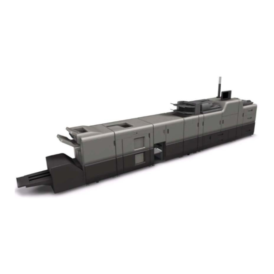
- Page 6 Taurus-C1 Training Full System - 1 (1) Main machine D074/D075/M044 (7) Multi Folding Unit (D521) (2) Decurl Unit (8) Ring Binder (D519) (3) A3/DLT LCIT (D516) (9) High Capacity Stacker (D515) (4) Multi Bypass Tray (D517) (10) Finisher (D512) (5) Buffer Pass Unit (D548) (11) Trimmer Unit (D520) (6) Cover Interposer Tray (D518) Slide 6...
- Page 7 Taurus-C1 Training Full System - 2 If the Trimmer Unit is not installed, the booklet tray (12) for the Booklet Finisher (D512) must be installed to hold stapled booklets. The booklet tray must be removed from the finisher in order to install the Trimmer Unit.
- Page 8 Taurus-C1 Training Full System - 3 The other finisher (D513) only does corner and flat stapling (no booklet stapling). The Trimmer Unit cannot be installed with this finisher (the Trimmer Unit processes booklet-stapled stacks only). Slide 8 No additional notes...
- Page 9 Taurus-C1 Training Other Options Original Tray USB 2.0/SD Slot Type E (TBD) A3/11"x17" Tray Unit (B331-12) Punch Unit (D449) for Finisher (D512/D513) VM Card Type R (with App 2 Me) @Remote Slide 9 No additional notes...
- Page 10 Taurus-C1 Training Security and Encryption Card The Data Overwrite Security and Data Encryption applications are provided from the factory on one SD card. The machine is shipped with this SD card in Slot The customer must enable these applications with user tools. Slide 10 No additional notes...
- Page 11 Taurus-C1 Training System Layout Slide 11 This is the same as the AG-C1/P1 and Aries.
- Page 12 Taurus-C1 Training New Fiery Controller E-41a with Standard Fiery Controller (E-41a) Optional FACI The Color Controller Type E-41a is standard this series. It is an external type controller with the same design concept as the QX100 controller for the AG-series. Slide 12 The E-41a is not compatible with the E-41.
- Page 13 Taurus-C1 Training Printing The machine has a GW controller, but it does not carry the GW printer application. All printing features are provided by the external Fiery E-41a controller. Slide 13 No additional notes...
- Page 14 Taurus-C1 Training Scanning The machine is equipped with a GW (Ricoh) scanner and a Fiery scanner as standard features. Both scanner features are available even when GW and Fiery controllers are connected to the network at the same time. Slide 14...
- Page 15 Taurus-C1 Training @Remote @Remote can acquire only a limited amount of information via the Fiery controller network port. For full functionality with @Remote, the system must be connected via the GW controller network as well. This means the machine needs two IP addresses for full function support with @Remote.
- Page 16 Taurus-C1 Training View with Front Covers Open PCDUs Cleaning Unit Left Drawer Right Drawer ITB Unit The left drawer contains the PTB (paper transport belt), fusing unit, paper cooling unit, and the 1st half of the duplex path. The right drawer contains the PTR (paper transfer roller) unit, paper registration, and the 2nd half of the duplex path Slide 16 No additional notes...
- Page 17 Taurus-C1 Training Internal Component Layout Slide 17 1. Attention Light: Not built-in. Must be installed during the installation procedure. 2. Operation Panel: Not built-in. Must be installed during the installation procedure. 3. ARDF 4. Toner Bank 5. Scanner Unit 6. Laser Units: There are two laser units. Each laser unit handles two colors (YM, CK).
- Page 18 Taurus-C1 Training Paper Feed Paths Slide 18 1. Original Path: ARDF (D074/D075 Only) 2. Paper Bank: Tray 1 (Tandem: 2,000 sheets), Tray 2 (Universal: 500 sheets) 3. Vertical Paper Path 4. LCIT: Tray 3 (1,000 sheets), Tray 4 (2,000 sheets), Tray 5 (1,000 sheets) 5.
- Page 19 Taurus-C1 Training Paper Input Paper Registration Unit Six possible paper sources. The paper from each source goes to the paper registration unit. This unit corrects skew (with a paper buckle adjustment) and side- to-side registration (with a CIS element and sliding shift roller). Slide 19 Paper is fed from six possible sources: (1): Tray 1 of the paper bank in the main machine, a tandem tray that holds...
- Page 20 Taurus-C1 Training Paper Feed (Straight Through) (1) Paper registration for skew and side-to-side correction (2) Toner image transfer to paper (3) Transport to the fusing unit via transport belt (4) Fusing unit (5) Paper cooling unit, and over the exit junction gate (6) Paper exit for face-up delivery Slide 20 No additional notes...
- Page 21 Taurus-C1 Training Paper Feed (Duplex) (6) Inverter junction gate (7) Inverter/duplex tray (8) Duplex path (9) Feed into the vertical transport path Slide 21 (1) to (5), (10), (11): See the previous slide. When the paper exits the paper cooling unit, the exit junction gate opens and directs the paper to the inverter junction gate at (6).
- Page 22 Taurus-C1 Training Paper Feed (Face-down Delivery, Purge) Green: Inversion Blue: Feed to purge tray Slide 22 No additional notes...
- Page 23 Taurus-C1 Training Printing Process Overview Drum PCDU ITB Bias Roller Image Transfer Belt (ITB) Image Transfer Roller Each PCDU has a drum with a drum cleaning unit, charge roller unit, and development unit around it. This configuration is the same in each PCDU. The toner image written onto each drum by the laser is attracted to the image transfer belt (ITB) by the positively charged image transfer rollers.
- Page 24 Taurus-C1 Training Specifications Slide 24 No additional notes...
- Page 25 Taurus-C1 Training Main Specifications (1) Taurus-C1/P1 Print Speed (A4/LT LEF) C1a: 65 ppm, C1b/P1: 75 ppm Toner Type Chemical Toner Fusing Type Oil-less Belt Fusing Print Resolution 1200 x 4800 dpi Max Paper Size 13” x 19.2” Max Paper Thickness Simplex: 300 g/m Duplex: 256 g/m Paper Thickness by tray (g/m...
- Page 26 Taurus-C1 Training Main Specifications (2) Taurus-C1/P1 Paper Input Capacity Mainframe: 2,500 Tray 1: 2,000 (1,000 x 2) Tray 2: 500 Options: 4,500 LCT Tray 1: 1,000 LCT Tray 2: 2,000 LCT Tray 3: 1,000 Bypass: 500 Paper Output Capacity Finisher Shift Tray 2500 (booklet finisher) 3000 (other finisher)
- Page 27 Taurus-C1 Training Main Specifications (3) Taurus-C1/P1 Maximum Original Size A3/DLT Maximum Printable Area 323 mm x 480 mm, 12.7” x 18.9” Warm-up Time Less than 300 seconds First Copy Output Time Less than 11 seconds Slide 27 Maximum Printable Area: Width can be expanded from 480 mm up to 630 mm (24.8 in.) by setting SP5150-1 to ON.
- Page 28 Taurus-C1 Training Comparison of Controller Specs AG-C1/P1 Aries-C1.5/P1.5, Taurus EFI Std. EFI Std. Base CTL Pro 80 System System8R2 System9R2 Type Integrated External Core2 Duo Core2 Duo 2.16GHz 3.00GHz Memory DDR2/2GB DDR2/2GB 500GB 160GB DVD Drive None Power From Mainframe External Supply FACI Kit...
- Page 29 Taurus-C1 Training Target Reliability Max Volume: 180k Recommended monthly volume range » Taurus-C1a: 30k to 110k » Taurus-C1b, Taurus-P1: 50k to 130k Recommended average monthly volume » Taurus-C1a: 50k » Taurus-C1b, Taurus-P1: 70k Max Life: 10,800k or 5 years Slide 29 Aries-P1.5/C1.5: Max Volume 350K, Max Life 21,000K AG-P1L/C1L: Max Volume 192K, Max Life 11,520K...
- Page 30 Taurus-C1 Training TCRU (ORU) A total of eight units can be replaced by TCRU trained operators: Drum cleaning unit (PCDU) OPC Drum (PCDU) Charge roller unit (PCDU) Fusing unit Fusing cleaning unit Paper transfer unit (contains the paper transfer roller) ITB cleaning unit Paper feed roller sets (one for each tray of the main machine, one for each tray of the LCIT, and...
- Page 31 Taurus-C1 Training TCRU (ORU) Developer is not a TCRU part for the Taurus series. The Fusing Unit is much lighter than AG/Aries. One person can replace this fusing unit, while two people are required to replace the AG/Aries fusing unit. Integrated TCRU firmware with multiple language support No SD card upgrade is necessary...
- Page 32 Taurus-C1 Training Replacement of Consumables During Printing The following can be replaced during printing, so that operation can continue without interruption: Paper Toner Waste toner bottle Slide 32 This is the first time that a waste toner bottle can be replaced without stopping operation.
- Page 33 Taurus-C1 Training Maintenance Slide 33 No additional notes...
- Page 34 Taurus-C1 Training PM Table The basic PM interval for the main machine is 300k. Many parts are replaced at 300k or at a multiple of 300k. Some important exceptions are: Developer and development unit filters » D074: 750K » D075, M044: 900K Drum * »...
- Page 35 Taurus-C1 Training Technology The Main Points about the Engine Slide 35 No additional notes...
- Page 36 Taurus-C1 Training Operations Operation Panel Settings Applications Alerts Not built-in. Must be installed during the installation procedure. 10.4-inch color LCD panel Keys are grouped according to basic categories The tilt and angle of the operation panel can be easily adjusted by the operator to reduce glare on the LCD.
- Page 37 Taurus-C1 Training Attention Light This new light is taller and can be seen from a long distance. Slide 37 This is similar to the attention light for the Aries-C1.5/P1.5.
- Page 38 Taurus-C1 Training Active Tray Indicator Each tray has an LED lamp. It shows whether paper is being fed from the paper tray. This helps the user to avoid opening a tray that is being used to feed paper, preventing some paper jams. Also, by knowing which trays are not being used, users can refill paper in trays that are not being used, to prepare for later jobs.
- Page 39 Taurus-C1 Training ARDF The ARDF is basically the same as the D014/D015. However, there are some minor differences: Design changes in the front cover, rear cover, feed cover, and handles. Color of the external covers has changed. Shoulder screws are rounded. Harness routing has changed.
- Page 40 Taurus-C1 Training SPR-Ceγ) New Toner ( Pulverized Toner New Toner (AG-C1 series) (Taurus-C1 series) Polyester Resin Colorant Scale: Scale: 10μm 10μm This toner is an extremely fine oil-less chemical toner of uniform size. This enables a smoother toner surface after fusing, and good adhesion to thick paper. This toner achieves the following improvements in comparison with pulverized toner.
- Page 41 Taurus-C1 Training New Laser Diode Technology VCSEL Array (40 Laser Diodes) Scanning Direction This model uses VCSEL (vertical cavity surface emitting laser). The VCSEL unit used in this model is a two-dimensional array of laser diodes. This allows high printing speed (up to 75 ppm) and excellent image quality (1200 x 4800 dpi).
- Page 42 Taurus-C1 Training Benefits of VCSEL Technology When printing duplex, some media/paper may shrink or expand after the front page goes through the fusing unit. Such changes in paper size may result in inaccurate registration on the front and back pages. VCSEL counteracts these problems.
- Page 43 Taurus-C1 Training Other Points about the Laser Unit To correct color registration, the skew motor in the laser unit adjusts the position of the mirrors. In some other models, a small motor attached to the BTL does this adjustment. The new VCSEL technology also improves mechanical performance by reducing the number of revolutions of the polygon motors.
- Page 44 Taurus-C1 Training New Type of OPC “Advanced Stabilization OPC” The Overcoat Layer is more durable. This improves the stability of the charge and produces more stable color during continuous printing jobs. Slide 44 No additional notes...
- Page 45 Taurus-C1 Training Liquid Cooling System for Developer (1) Pump Developer Pipe Radiator In addition to the air cooling ducts and fans, this machine has a liquid cooling system for the developer in the PDCU. The radiator cools the liquid, which is pumped to the development unit to keep the temperature of the developer at the correct level.
- Page 46 Taurus-C1 Training Liquid Cooling System for Developer (2) Liquid coolant is pumped from a tank [1] and circulated through the jackets of the development units through two hoses [2]. The rubber tubing is guaranteed for 20 years of use at 70°C (158°F). Rate of evaporation of coolant: 150 cc/7 years at 32°C...
- Page 47 Taurus-C1 Training Fresh Toner Contains Developer Toner in each toner bottle is pre-mixed with a small amount of developer. This prevents density fluctuation during high color coverage and large volume printing. Slide 47 No additional notes...
- Page 48 Taurus-C1 Training PCDU (1) Charge Unit This machine uses charge rollers to charge the drums. There are no charge corona units. This reduces the amount of ozone created by the machine. There is a charge roller cleaning roller [A] above the charge roller [B] in each PCDU.
- Page 49 Taurus-C1 Training PDCU (2) Drum Cleaning Unit There are mylars [A] above the used toner transport coil [B] in each PCDU. The slight vibration set up by the auger turning against the mylar prevents used toner from clumping when it is transported out of the back of the unit .
- Page 50 Taurus-C1 Training Toner Bottles This machine uses RFID (Radio Frequency IDentification) technology. Each reader PCB [A] is paired with a tag PCB [B] on top of each toner bottle. Slide 50 No additional notes...
- Page 51 Taurus-C1 Training Toner Bottles The toner bottles are designed for easy handling and replacement. They can be replaced by the operator from a seated position. Slide 51 No additional notes...
- Page 52 Taurus-C1 Training Replacing the Toner Bottle An empty toner bottle [1] can be replaced while the machine is printing. After the machine signals toner end for a bottle, there is still enough toner in the sub hopper [2] for the machine to print 480 sheets (A4 LT @ 5% coverage).
- Page 53 Taurus-C1 Training Replacing the Used Toner Bottle The used toner bottle is at the lower left corner of the main machine behind the left door. Just pull it out by its handle. The cap [1] of the used toner bottle has a reverse thread. Turn it clockwise to remove it.
- Page 54 Taurus-C1 Training Replacing the Used Toner Bottle When the used toner bottle [1] is full, it can be removed and replaced with an empty bottle while the machine is operating. The reservoir [2] above the bottle can continue to receive and hold used toner while the bottle is out of the machine.
- Page 55 Taurus-C1 Training Changes to Process Control New ‘active toner control’ technology samples the pixel count rapidly at set intervals of time. Increasing the number of samples ensures even density in filled areas. In previous machines, patterns were sampled during process control after each printed sheet. This new technology also takes into account the time for newly added toner to get from the toner inlet to the development roller/drum interface via...
- Page 56 Taurus-C1 Training Components used during Process Control D016 series Taurus-C1/P1 This machine has three ITB sensors (see above). Only the middle sensor functions as an ID sensor, but all three sensors are active MUSIC sensors. Two temperature/humidity sensors are used during process control.
- Page 57 Taurus-C1 Training Cleaning Units: Common Design One basic cleaning and lubrication mechanism is used in key components of the machine. A cleaning blade [1], lubricant roller [2], lubricant bar [3], and lubricant blade [4] are the cleaning mechanisms (with some variation) in the following units: [A] Drum cleaning unit [B] ITB cleaning unit...
- Page 58 Taurus-C1 Training Paper Feed (1) Paper Transport Unit The paper is held onto the paper transport belt by three fans: Rear, Front, Center. Compared to previous machines: » The paper transport unit frame of this machine is made of plastic, making it lighter for TCRU trained operators to handle.
- Page 59 Taurus-C1 Training Paper Feed (2) Paper Registration The high-precision paper registration unit used in the D016 has been adopted for use in this machine. The position of the paper in the paper path is corrected twice by the paper registration unit in the main machine, once to correct for skew and once for side-to-side registration.
- Page 60 Taurus-C1 Training Paper Tray Heaters The paper tray heaters (x2) can be switched on/off. Default: OFF. The tray heaters do not require installation or connection at installation. Slide 60 The left switch controls the heaters in the paper trays (paper bank and LCIT). The right switch controls the ITB heaters.
- Page 61 Taurus-C1 Training Image Transfer Unit (1) Two motors raise and lower the ITB. One motor operates the left tray (contains the components for YMC) and one motor operates the right tray (K). The belt centering sensor for this machine is simpler than the D016.
- Page 62 Taurus-C1 Training Image Transfer Unit (2) This machine uses the same steering control mechanism as the D016. This mechanism checks and corrects the positioning of the ITB to keep it centered and prevent color offset in images. A sensor at the right upper corner [1] of the ITB unit constantly monitors the position of the ITB.
- Page 63 Taurus-C1 Training Image Transfer Unit (3) Previous Models This Model The location of the ITB sensor array (ID and MUSIC sensors) has changed. In previous machines, the ITB sensor array [A] is located farther downstream and below the ITB. In this machine, the ITB sensor array [B] is located above the ITB on the right end of the ITB unit below the K_PCDU.
- Page 64 Taurus-C1 Training New ITB/PTR Separation Mechanism When the right drawer is closed, a strong spring below the PTR unit rotates two cams up that lock the PTR [1] up against the bias roller [2] of the ITB unit. The bias roller rotates freely around the cam shaft [4]. When the PTR separation motor [5] turns on, the belt [6] turns the cam shaft counter-clockwise until the actuator [7] of the PTR separation sensor [8] rotates out of the sensor (this stops the motor).
- Page 65 Taurus-C1 Training New ITB/PTR Separation Mechanism The cams are rotated down to separate the bias roller and the PTR at the following times: Ready mode. After the machine enters Ready mode. This keeps the PTR separated from the bias roller. If the rollers were to remain in contact while the machine is idle, the hard surface of the PTR would deform the shape of the soft bias roller.
- Page 66 Taurus-C1 Training Printing on 300 gsm Paper (1) The paper path was designed to support 300 gsm from Tray 1 (256 gsm for duplex). The height of the machine is less than Aries, so the arcs of curvature in the feed path were made wider. Number of rollers increased from 2 to 4, and Smoother curvature of changed the roller position compared with the...
- Page 67 Taurus-C1 Training Printing on 300 gsm Paper (2) Tray 4 The middle tray of the optional LCIT (Tray 4) can also feed 300 gsm paper. All trays can feed coated paper, without installing special rollers. Only the stacker and buffer pass unit can handle 300 gsm paper. The other peripherals can pass this paper straight through, but cannot carry out finishing operations.
- Page 68 Taurus-C1 Training Printing on 300 gsm Paper (3) Unlike the AG/Aries series, this machine’s printing speed slows down by 30% for paper thicker than 220 gsm. Slide 68 No additional notes...
- Page 69 Taurus-C1 Training Improved Fusing Unit The fusing unit is lighter than the Aries. It can be lifted and carried by one service technician. Even though the fusing unit is light (17 kg), it can exert enough fusing pressure for printing on thick or textured paper.
- Page 70 Taurus-C1 Training Fusing Belt Cleaning There is no fusing belt cleaning roller. The cleaning fabric touches the surface of the pressure roller directly. There is no oil supply mechanism for lubricating the fusing belt in this machine. In this machine, the web end sensor of the fusing cleaning unit is a photo-sensor.
- Page 71 Taurus-C1 Training Decurler Unit The decurler unit is an option, but it is strongly recommended that you install it. This unit fits into the left side of the main machine. It has no purge tray (the purge tray is built into the main machine). The decurl unit corrects both convex and concave curling, a common problem with thin paper and prints with high toner coverage.
- Page 72 Taurus-C1 Training Purge Tray After a jam, paper that has not left the main machine is moved to the purge tray on the left side of the main machine. This eliminates the task of searching for every sheet remaining in the main machine or LCIT after a jam occurs downstream.
- Page 73 Taurus-C1 Training Reduction of Wear on Components As in previous machines, this machine has mechanisms to separate parts where pressure is exerted during normal operation. These mechanisms reduce wear on parts and prolong service life of components. ITB lift mechanism ITB/PTR separation mechanism Pressure roller lift mechanism Slide 73...
- Page 74 Taurus-C1 Training Technology Main Points about the Peripherals Slide 74 No additional notes...
- Page 75 Taurus-C1 Training Basic Points The covers of all peripheral units have been re- designed to match the shape and color of the main machine. There are no breaker switches in the peripheral units (except for the ring binder). Inspect and test the breaker switches at least once a year.
- Page 76 Taurus-C1 Training Two Basic Systems There are two basic configurations, depending on the type of finisher installed at the end of the line. Standard finisher system Booklet finisher system It is also possible to install without either of these finishers, but in this case, a stacker must be installed.
- Page 77 Taurus-C1 Training Two Basic Systems System with SR5040 Booklet Finisher Folding Unit Interposer Ring Binder Buffer Pass Unit Booklet Finisher Stacker GBC Punch Trimmer Taurus-C1a/b Bypass Tray System with SR5030 Finisher Plockmatic Finisher Bookletmaker Taurus-P1 Slide 77 Note that the peripherals are similar to existing models, but they are all new models because of the new two-tone cover coloring for the Taurus series.
- Page 78 Taurus-C1 Training Peripherals (1) Multi Bypass Tray BY5010: Similar to the Katana-C2 LCIT RT5060: Similar to the Katana-C2 A3/DLT LCT There is no optional A4/LT LCT. Only one LCT can be installed. A3/11"x17" Tray Unit TK5010 : Similar to the Katana-C2 Decurler Unit DU5010: Similar to the Katana-C2 Buffer Pass Unit Type 5010: Similar to the Aries-C1.5 Cover Interposer Tray CI5020 (two trays): Similar to the...
- Page 79 Taurus-C1 Training Peripherals (2) High Capacity Stacker SK5020 (5,000-sheet stacker): Similar to the Katana-C2 and Aries-C1.5 (SK5010) Roll-Away Cart Type 5010: A spare cart for SK5020 (one cart is included with the SK5020) Finisher SR5030 (no saddle stitching): Similar to the Katana-C2 and Aries-C1.5 (SR5020) Booklet Finisher SR5040 (with saddle stitching): Similar to the Katana-C2 and Aries-C1.5 (SR5020)
- Page 80 Taurus-C1 Training LCIT (1) Side fence adjustment The side fence adjustment mechanism of the LCIT has been re- designed to make it easier to change paper sizes. The side fences can be adjusted by loosening the screws and sliding the fences (see above).
- Page 81 Taurus-C1 Training LCIT (2) There is a new mechanism at the paper exit to retract the exit idle roller from the paper. This releases the paper for side-to-side registration in the main machine. The mechanism consists of a motor [A] on the back of the unit and the idle roller HP sensor [B] at the LCIT paper exit.
- Page 82 Taurus-C1 Training LCIT (3) The LCIT jam release mechanism has been re-designed for "one-action" removal. Slide 82 No additional notes...
- Page 83 Taurus-C1 Training Buffer Pass Unit Installed on the left side of the main unit, this option allows paper and toner to cool before it is fed to downstream peripherals. This prevents toner from sticking to other sheets of paper after stacking. It contains 8 fans.
- Page 84 Taurus-C1 Training Cover Interposer Paper Path The unit is taller than the previous model. The paper feed path is 20 mm longer but there are no added rollers. Installation The black mylar is no longer required for connection to the next peripheral unit downstream.
- Page 85 Taurus-C1 Training Multi-folding Unit There is a new ‘Glossy paper mode’ (half speed). The 1st fold motor and crease motor have been replaced by motors capable of slower speeds to accommodate half- speed mode for glossy paper. Elimination of stripe tracks at the leading edges of folded coated paper.
- Page 86 Taurus-C1 Training Multi-folding Unit: Types of Folding 2-Fold Z-Folding 3-Fold (In) 3-Fold (Out) 4-fold (Gate Fold) 4-fold (Double Parallel) The types of folding are the same as the previous model. Slide 86 No additional notes...
- Page 87 Taurus-C1 Training Multi-folding Unit: Modifications Overview The diagram shows the locations of the modifications. The next few slides explain the modifications. Slide 87 No additional notes...
- Page 88 Taurus-C1 Training Multi-folding Unit: Modifications [1] Roller marks on coated paper The exit roller has been replaced with the same type of roller used in the High Capacity Stacker, to reduce roller marks on coated paper. [2] Gate folded (FM6) cloth coated paper fold position The gap before and after the guide plate of...
- Page 89 Taurus-C1 Training Multi-folding Unit: Modifications [3] Improved feed-out of small Z-folded paper An extra drive roller [A] above the exit roller [B] at the top tray exit has been added to improve feed-out of small Z- Folded (FM1) paper. Slide 89 No additional notes...
- Page 90 Taurus-C1 Training Multi-folding Unit: Modifications [4] Improvement in multiple folding The entrance roller [A] and other transport rollers are driven independently. This allows effective control of the line speed while paper is fed from the main machine. Slide 90 No additional notes...
- Page 91 Taurus-C1 Training Multi-folding Unit: Modifications [5] Elimination of roller marks during multiple folding The movement of the TE stop pawl [A] raises and lowers the paper for registration. At the same time, the transport rollers stop rotating, to prevent the rollers from marking the paper.
- Page 92 Taurus-C1 Training Multi-folding Unit: Modifications [6] Elimination of damage to leading edges of paper Above the 1st feed roller [A], the guide plate [B] above the nip has been lengthened, and the width of the path has been narrowed, to prevent distortion of the leading edges of paper.
- Page 93 Taurus-C1 Training Multi-folding Unit: Modifications [7] Improved folding for coated paper The guide plate [A] can be moved to widen the space in the turn of the transport path, for easier folding with the fold plate. Slide 93 No additional notes...
- Page 94 Taurus-C1 Training Multi-folding Unit: Modifications [8] Elimination of roller marks when two sheets are folded When two sheets are folded at the same time, the 2nd fold roller [A] pulls away to widen the 2nd nip [B]. Slide 94 No additional notes...
- Page 95 Taurus-C1 Training Multi-folding Unit: Modifications [9] Elimination of wrinkling in gate-folded large paper sizes The shape of the FM6 pawl [A] has been changed [B] to prevent the wrinkling of large paper sizes during FM6 (gate) folding. Slide 95 No additional notes...
- Page 96 Taurus-C1 Training Multi-folding Unit: Modifications [10] Prevention of early top tray full alert with FM1 folding large paper sizes An auxiliary tray [A] keeps Z-folded paper (FM1) flat in the tray so that a trailing edge does not trigger an early tray- full alert in the top tray.
- Page 97 Taurus-C1 Training Multi-folding Unit: Modifications [11] Prevention of early top tray full alert with FM3 folding The trailing edge of a multi- folded sheet can open, and trigger an early top-tray full alert. A flexible page depressor [A] is provided as an accessory, to prevent folded paper (especially FM3 Letter Fold- out sheets) from triggering an...
- Page 98 Taurus-C1 Training Ring Binder The surge PCB [A] has been removed and a noise filter [B] has been added. Slide 98 No additional notes...
- Page 99 Taurus-C1 Training Stacker Stacking The stacker can stack up to 5,000 sheets (SRA3, A4, LT size) on the shift tray and 250 sheets on the proof tray. One roll-away cart is provided with the stacker. Additional carts are available as options. Only one stacker can be installed.
- Page 100 Taurus-C1 Training Finishers Minor changes: The pre-stacking tray can hold 5 sheets of paper. Slide 100 No additional notes...
- Page 101 Taurus-C1 Training Trimmer Minor changes: Transport belt. The color of the transport belt changed to white. This prevents dirty images on A3 Full-bleed paper. Entrance guide. The shape of the movable entrance guide has been modified to prevent pages from slipping. New sensor.
- Page 102 Taurus-C1 Training Technology Paper Library Slide 102 This section will explain the Paper Library feature. It is the same as the Aries series, with a few extra parameters that can be adjusted for each paper type.
- Page 103 What is the Paper Library? This new feature simplifies paper settings at the operation panel. A wide range of paper profiles are supplied by Ricoh. The data must be copied to the machine during the installation procedure. It is not installed at the factory. Updates are provided on an SD card.
- Page 104 Taurus-C1 Training How does it Work? EFI Controller Update Base Machine Custom Paper List Tray Paper Select User Paper List Tray Management Registration Paper Library Max 100 Profiles 1,000 Provided Profiles Recall Backup Profiles Paper Catalog Modified Profiles Saved Paper Library Selected Profiles Real Time Synchronization...
- Page 105 Taurus-C1 Training How does it Work Registration Paper Library Custom Paper List 1,000 Provided Profiles Max 100 Profiles Assign to Paper Tray Saved Paper Backup Library Can contain up to Recall 1,000 profiles Backup SD Card You can build up a saved paper library of up to 1000 profiles. This can be copied to other machines of the same model with an SD card.
- Page 106 Taurus-C1 Training Basic Operation Overview Access the Paper Library. This is done from the Tray Paper Settings screen. Then select one or more paper profiles from the Paper Library, and register them in the Custom Paper List. Go back to the Tray Paper Settings screen. Then select the paper type from the Custom Paper List and assign it to one of the paper trays.
- Page 107 Taurus-C1 Training Basic Operation 1. To Access the Tray Paper Settings Press the Tray Paper Settings button on the Operation Panel. Slide 107 No additional notes...
- Page 108 Taurus-C1 Training Basic Operation 2. To Access the Paper Library Access the Tray Paper Settings screen and touch ‘Paper Library’. Slide 108 This slide shows the Tray Paper Settings screen for the new series. We will talk about it a bit more later. Note that the names of the buttons at the top right of the screen have been changed to Paper Library and Custom Paper.
- Page 109 ‘Exit’. Slide 109 Paper Library: This is the data that was copied from the SD card from Ricoh. Saved Paper Library: These are the customized paper types that the user has backed up from the Custom Paper List.
- Page 110 Taurus-C1 Training Basic Operation 4. To Select a Paper Type for a Tray from the Custom Paper List On the Tray Paper Settings screen, touch the tray that you want to select paper for. Slide 110 No additional notes...
- Page 111 Taurus-C1 Training Basic Operation 5. To Select a Paper Type for a Tray from the Custom Paper List There are two windows: Tray Paper Settings screen: This is the same as in previous models. Recall Custom Paper screen: This allows you to select a paper profile from the Custom Paper List.
- Page 112 Taurus-C1 Training Other Ways to make a Custom Paper Type You can register a paper type from the Paper Library, and modify the settings. You can make a new Custom Paper Type, starting from nothing. You can modify an existing Custom Paper Type. You can delete an existing Custom Paper Type.
- Page 113 Taurus-C1 Training To See the Custom Paper List Access the Tray Paper Settings screen and touch ‘Custom Paper’. Slide 113 No additional notes...
- Page 114 Taurus-C1 Training Custom Paper List To edit a profile, use the ‘Program/Change’ button. To delete a profile, use the ‘Delete’ button. None of these functions affect the original data that was copied to the GW controller from the SD card. Slide 114 No additional notes...
- Page 115 Advanced Settings are explained in the ‘Adjustment Item Menu Guide: TCRU/ORU’ manual (section 4. Details of Menu Items in Advanced Settings). Adjustable Parameters for each paper type Not adjustable in profiles provided by Ricoh Paper Type, Thickness, Color, Coated/Uncoated, Punch (on/off), Paper Brand Name...
- Page 116 Security SD card that is in SD card slot 1. Updating the Paper Library A modified Paper Library will sometimes be made available from Ricoh on an SD card. This can then be copied to the machine by a technician. Automatic Synchronization with the Paper Catalog in the...
- Page 117 Taurus-C1 Training Backing up the Custom Paper List To save a Custom Paper List to a backup area in the paper library area of the GW controller memory, touch ‘Save to Paper Library’. This includes modifications to paper profiles that were made by the user.
- Page 118 Taurus-C1 Training Backing up the Custom Paper List The Saved Paper Library has space for 1000 paper types, but the Custom Paper List is only 100 paper types. So, after backing up the Custom Paper List, you can delete everything and store another 100 paper types, and back these up to the Saved Paper Library.
- Page 119 Taurus-C1 Training Copying the Saved Paper Library To copy the Saved Paper Library to an SD card, use SP 5- 711-102. To copy this data from the SD card to another machine, use SP 5-711-2. Registration Paper Library Custom Paper List Assign to 1,000 Provided Profiles Max 100 Profiles...
- Page 120 Taurus-C1 Training Copying the Saved Paper Library New function SD Card Flash memory user.mqp Paper Library Saved Paper Library SD Card Registration Backup Recall NVRAM SP5711-001 Library.mqp Custom Paper Library SP5711-002 user.mqp SP5711-102 Customers can back up the Saved Paper Library data onto the SD Card in slot 1 that contains the Data Overwrite Security application.
- Page 121 SD card, so operators can maintain the latest profiles in their machines. If profiles are updated by Ricoh, they can be supplied on a new SD card and transferred to the machine. Slide 121 The update by SD Card overwrites the Paper Library only.
- Page 122 Taurus-C1 Training Checking the Version of the Printer Library Data Use these SP Modes: SP5711-201: Version display of Library.mqp on the Flash ROM SP5711-202: Version display of Library.mqp on the SD Card Slide 122 No additional notes...
- Page 123 Taurus-C1 Training Checking the Version of a Profile In the Tray Paper Settings screen, touch Custom Paper. Then touch ‘Check Product Name’. The name of the paper type and the version of the profile appear. Slide 123 No additional notes...
- Page 124 Taurus-C1 Training Where is the Data Stored in the Machine? On the GW Controller board Paper Library, Saved Paper Library: In Flash Memory » If the board is broken, this data is probably all gone. » So, after replacing the board: –...
- Page 125 Taurus-C1 Training Linkage to the EFI Controller Synchronization Fiery Controller Mainframe The Custom Paper List (in the mainframe) is linked with the Paper Catalog (in the Fiery Controller). The paper profiles can be managed in either of the above. Any changes in one are automatically reflected in the other.
- Page 126 Taurus-C1 Training EFI Command Workstation Click here when you need to access the Paper Catalog The Consumables tab shows the paper types that are set for each tray. Double-click a tray to change the paper type for that tray. Slide 126 No additional notes...
- Page 127 Taurus-C1 Training Paper Catalog Here, profiles can be edited or added. Changes are automatically reflected in the Custom Paper List in the mainframe. Slide 127 No additional notes...
- Page 128 Taurus-C1 Training Installation Preliminary Notes Slide 128 No additional notes...
- Page 129 Taurus-C1 Training Breaker Switch The machine has a breaker switch at the rear lower right corner. Inspect and test the breaker switch at least once a year. Slide 129 There are no breaker switches in the peripheral units (except for the ring binder).
- Page 130 Taurus-C1 Training Space Required for Opening Covers (1) Front Doors: Both doors swing open to the front (2) Main Machine (3) Cooling Box: Swings open to the rear (4) Controller Box: Swings open to the rear (5) Left Drawer: Slides open to the front for servicing (fusing unit, etc.) (6) Right Drawer: Slides open to the front for servicing (registration unit, etc.) The rear boxes (cooling box and controller box) are on hinges and can be swung open to the rear in order to service parts on the back of the machine (motors,...
- Page 131 Taurus-C1 Training Rear Covers Open Controller Box Cooling Box This is a view of the rear of the machine with the cooling box and controller box open. The cooling box contains the liquid cooling system for the development units. Slide 131 No additional notes...
- Page 132 Taurus-C1 Training Turning the Machine On 1. Turn on the main power switch of the main machine. 2. Turn on the switch on the back of the Fiery Controller box. See the top diagram on the left. 3. Press and turn on the switch on the front of the Fiery Controller box.
- Page 133 Taurus-C1 Training Turning the Machine Off On the Fiery controller operation panel: 1. Press the [Fiery] tab. 2. Press the [Restart Fiery] button. 3. Press the [Shut Down] button. On the Main Machine 1. Push the operation switch on the operation panel to turn the power off.
- Page 134 Taurus-C1 Training Installation Main Machine Slide 134 This section explains only the main points about the installation procedure. For full details, see the field service manual.
- Page 135 Taurus-C1 Training Outline of the Installation Procedure (1) Do the following, with the machine's power off. Unpack the Machine » It is necessary to use a forklift to remove the machine from its pallet. Install the Attention Light Install the Operation Panel Connect the ARDF »...
- Page 136 Taurus-C1 Training Outline of the Installation Procedure (2) Connect the Main Machine to the Power Source and turn the Power On. Keep the covers closed. Note that developer installation and TD sensor initialization are done at the factory before shipping. There is nothing to do with developer during the installation procedure.
- Page 137 Taurus-C1 Training Outline of the Installation Procedure (3) Fiery Controller Connection Fiery Controller Setup Paper Library Data Installation Finishing the Installation Slide 137 This is an outline of the installation procedure. Important points will be mentioned in the next few slides. See the service manual for full details.
- Page 138 Taurus-C1 Training ITB Lever (1) The ITB lever is shipped in this location, secured by tape. Slide 138 No additional notes...
- Page 139 Taurus-C1 Training ITB Lever (2) Attach the ITB lever to the tip of the shaft [1]. Rotate the lever up [2] to lock the ITB in place. Slide 139 No additional notes...
- Page 140 Taurus-C1 Training Installing the Operation Panel There are four ways to install the operation panel: Positions 1 to 3 (Standard, Standard Diagonal, Standard Diagonal Extended) are for use in a standing position. Position 4 (Easy Access) is for use in a seated position. Installation for positions 1 and 4 is explained in the installation procedure.
- Page 141 Taurus-C1 Training Operation Panel at the ‘Seated’ Position If the operation panel [A] is fully depressed, the toner bank door [B] cannot be opened. To open the toner bank door, swing the operation panel up [1], and then open the door [2]. Slide 141 No additional notes...
- Page 142 Taurus-C1 Training Attach the Fusing Roller Knob Holder (1) Left Front Door This knob can be attached as shown and rotated by hand to feed jammed paper out of the fusing unit. This knob is stored in a holder that must be attached to the inside surface of the left front door.
- Page 143 Taurus-C1 Training Attach the Fusing Roller Knob Holder (2) Attach the holder as shown on the left. Insert the knob, which is in the accessories box, in the holder as shown on the right. Slide 143 To use the knob, insert in the hole in the fusing unit’s front cover and turn clockwise, as shown below.
- Page 144 Taurus-C1 Training Install the Toner Bottles (1) Rock the bottle gently to loosen the contents of the toner bottle. Slide 144 No additional notes...
- Page 145 Taurus-C1 Training Install the Toner Bottles (2) Turn the bottle so that the toner port [1] is down and the RFID chip [2] is up, with the protrusions [3] lined up with the cutouts in the cover. The front end of each toner bottle has protrusions that fit into cutouts in each color holder.
- Page 146 Taurus-C1 Training Removing a Toner Bottle To remove a toner bottle, push the lever [1] to the left. The bottle [2] jumps out a short distance. Grip the bottle by its knob holder and pull it out of the machine. While holding the bottle by its knob holder at the front, support the end of...
- Page 147 Taurus-C1 Training Connecting the Fiery Controller You must use the shielded LAN cable provided with the accessories to connect the Fiery Controller box and the main machine. Slide 147 No additional notes...
- Page 148 Taurus-C1 Training Fiery Controller Selection Set SP5193-001 to ‘6’ (Fiery controller). There is no Creo controller. Do the Fiery controller settings. You must do the Fiery controller settings immediately after you turn the machine on for the first time. Slide 148 No additional notes...
- Page 149 Taurus-C1 Training Install the Paper Library Data The paper library data is not included in the machine when it is shipped. It must be copied to the machine during the installation procedure. Follow the procedure in the service manual. Slide 149 Installation >...
- Page 150 Taurus-C1 Training Completing the Installation Load the paper trays. Make sure that the Tray Paper Settings are set up correctly. Print the SMC Report (SP5990-6). Make a test copy. Do ACC if necessary. MUSIC Color Registration Adjustment 1. Push [User Tools]. 2.
- Page 151 Taurus-C1 Training Concerning the Tray Heaters (1) The tray heaters for the main machine are built-in and connected, but they are switched off before the machine leaves the factory. The left switch controls the heaters in the paper trays (paper bank and LCIT). The right switch controls the ITB heaters.
- Page 152 Taurus-C1 Training Concerning the Tray Heaters (2) When these switches are ON, the heaters turn on when the main machine is turned off (or enters energy save mode), and then turn off when the main machine is turned on again (or leaves energy save mode).
- Page 153 Taurus-C1 Training Removing the Cooling Box and Controller Box If the machine cannot fit through a door, the cooling box (1) and controller box (2) can be removed. With both boxes removed, the machine is 750 mm (30 in.) wide. There are detailed procedures for removal in the service manual.
- Page 154 Taurus-C1 Training Moving the Machine (1) Front Left Side The machine is extremely heavy. When it is necessary to move the machine even a short distance to re-locate it, apply pressure only on the areas that are marked with red squares in the illustrations. Slide 154 No additional notes...
- Page 155 Taurus-C1 Training Moving the Machine (2) Right Side Rear The machine is extremely heavy. When it is necessary to move the machine even a short distance to re-locate it, apply pressure only on the areas that are marked with red squares in the illustrations. Slide 155 No additional notes...
- Page 156 Taurus-C1 Training Installation Peripheral Units: Decurler Slide 156 This section explains only the main points about the installation procedures. For full details, see the field service manual.
- Page 157 Taurus-C1 Training Installing the Decurler Unit (1) Lay the Decurler Unit [A] on the carton box [B] as shown above so that the entrance gate of the decurler unit does not touch any object or the floor. Keep this position before attaching this unit to the main machine. Do not lay the Decurler Unit on the floor with the entrance gate of the decurler unit facing downward.
- Page 158 Taurus-C1 Training Installing the Decurler Unit (2) Follow the instructions in the service manual when connecting the harnesses. Some have identical shapes, but different colors, to prevent connection to the wrong place. Be careful not to leave slack in the harnesses, or there will be trouble when opening the left drawer.
- Page 159 Taurus-C1 Training Installing the Decurler Unit (3) You must select the correct entrance guide plate to attach to the next peripheral downstream from the decurler unit. This depends on which peripheral is immediately downstream. Each guide plate is marked to tell you which guide plate to install. Multi Folding Unit: A Ring Binder: A Cover Interposer Tray: A...
- Page 160 Taurus-C1 Training Installing the Decurler Unit (4) When you attach guide plate A to the downstream unit: There are two sets of holes on guide plate A. Attach the screws to the outer holes (marked above by the red arrows) if the next downstream unit is the Multi Folder unit.
- Page 161 Taurus-C1 Training Installing the Decurler Unit (5) After installing the decurler, some SP settings must be made. Refer to the accessory sheet and enter the settings for SP1927 and SP1928. Exit SP mode and turn off the main machine. Slide 161 No additional notes...
- Page 162 Taurus-C1 Training Docking the First Downstream Peripheral 1. Connect and dock the downstream peripheral unit to the main machine. 2. Turn on the main machine. 3. Do SP5804-210. This sets the upper path in the decurl unit as the default paper path. 4.
- Page 163 Taurus-C1 Training Connection Brackets Between Downstream Peripherals If the peripheral unit has a single-piece connecting bracket attached at the downstream side, the bracket can be used to adjust side-to-side registration on the unit where it is attached. Slide 163 No additional notes...
- Page 164 Taurus-C1 Training Curl Correction Do some test prints and check for excessive curling. Do test prints with paper feed from each paper tray. Curl correction is done with settings in the SP mode. There are six SP codes for curl correction, one for each paper tray.
- Page 165 Taurus-C1 Training Installation Peripheral Units: LCIT, Bypass Tray Slide 165 This section explains only the main points about the installation procedures. For full details, see the field service manual.
- Page 166 Taurus-C1 Training Before Docking the LCIT If you will install the Multi Bypass Tray or the LCIT tray heaters (or both), do this before you dock the LCIT to the right side of the main machine. Docking: Carefully follow the procedure in the service manual, to make sure that cables and ground wires are not damaged.
- Page 167 Taurus-C1 Training Docking the LCIT to the Machine Push the LCIT close to the left side of the main machine. On the left side of the main machine [1], check the height of the of the LCIT paper exit [2]. Move the main machine entrance plate [3] up and down and confirm that it does not contact the paper exit of the LCIT.
- Page 168 Taurus-C1 Training Special Rollers for Coated Paper This LCIT can handle coated paper without replacement of the pick-up, feed, and separation rollers. Slide 168 No additional notes...
- Page 169 Taurus-C1 Training Tray Heaters These are not included inside the LCIT. They must be installed by the technician. Slide 169 Installation > A3/DLT LCIT (D516) > LCIT Tray Heaters...
- Page 170 Taurus-C1 Training Installation Peripheral Units: Paper Handling Units (General Notes) Slide 170 No additional notes...
- Page 171 Taurus-C1 Training Common Procedures Before you dock the peripheral, make sure that you install the correct set of sponges. If you dock a peripheral directly to the main machine, the procedure is different from when you dock the peripheral to another peripheral. After installing each unit, do the following: Set the leveling shoes and adjust the height of the unit.
- Page 172 Taurus-C1 Training Installation Peripheral Units: Buffer Pass Unit Slide 172 This section explains only the main points about the installation procedures. For full details, see the field service manual.
- Page 173 Taurus-C1 Training Important Note The buffer pass unit is unstable (top-heavy) and can fall over easily. To avoid personal injury or damage to the unit, use caution when you pull out the buffer pass unit drawer [A], until the unit has been docked to the main machine. Slide 173 No additional notes...
- Page 174 Taurus-C1 Training Installation Procedure Unpack the unit. Remove the shipping brackets. Dock it to the main machine. Attach the connecting bracket for the next downstream peripheral. Slide 174 Installation > Buffer Pass Unit Type 5010...
- Page 175 Taurus-C1 Training Mylars Mylars must be attached at these locations: Entrance guide of the buffer pass unit (diagram on the left). Entrance guide of the next downstream peripheral (diagram on the right) Slide 175 Full details of how to attach these mylars are shown in the service manual. Installation >...
- Page 176 Taurus-C1 Training Installation Peripheral Units: Cover Interposer Unit Slide 176 This section explains only the main points about the installation procedures. For full details, see the field service manual.
- Page 177 Taurus-C1 Training Cover Interposer Tray Unit Transport Unit The cover interposer tray contains two units, as shown above Tray unit Transport unit Slide 177 No additional notes...
- Page 178 Taurus-C1 Training Important Note about the Cover Interposer Always remove the tray unit from the transport unit at the following times: Before you disconnect either the cover interposer tray or the next peripheral device to the left Before you do any maintenance on either the cover interposer tray or the next peripheral device to the left.
- Page 179 Taurus-C1 Training Installing the Cover Interposer First, dock the transport unit of the cover interposer to the copier. Important: Do not put the tray unit on the top of the cover interposer at this time. Then, install the next device to the left of the cover interposer.
- Page 180 Taurus-C1 Training Installation Peripheral Units: Folder Unit Slide 180 This section explains only the main points about the installation procedures. For full details, see the field service manual.
- Page 181 Taurus-C1 Training Auxiliary Tray and Fold Depressor Fold Depressor Auxiliary Tray These items are available, but they are not accessories. The auxiliary tray keeps Z-folded paper (FM1) flat in the tray, so that the trailing edges do not trigger an early tray full alert in the top tray.
- Page 182 Taurus-C1 Training Installation Peripheral Units: Ring Binder Slide 182 This section explains only the main points about the installation procedures. For full details, see the field service manual.
- Page 183 Taurus-C1 Training Correct Lifting Method Top Cover: DO Do not lift by the top NOT LIFT HERE cover. This will damage the cover. Always lift at the base. Base: Lift here Slide 183 No additional notes...
- Page 184 Taurus-C1 Training Removing Shipping Materials Do not discard these Braces: Do not braces. throw away They must be reattached to the finisher before it is moved or shipped to another location. Slide 184 No additional notes...
- Page 185 Taurus-C1 Training Ring Supply Indicator Attach the indicator to the ring supply cartridge. Ring Supply Cartridge Indicator Slide 185 No additional notes...
- Page 186 Taurus-C1 Training Jams Decals attached to the machine that provide guidance for removing paper jams. Point out the decal locations to the customer. Detailed instructions on removing ring jams are provided in the operating instructions under "Removing Jammed Ring Combs". Slide 186 Inform the above to the customer.
- Page 187 Taurus-C1 Training Pulling out/Pushing in the Binder Unit Always grip handle Mc8 when pulling out or pushing in the binder unit. Never touch any other surface of the binder unit when it is moving. To avoid injury the fingers, never push on the top of the binder unit to slide it back into the finisher.
- Page 188 Taurus-C1 Training Do not Store Things Below the Output Tray Do not use the empty space below the output tray as a storage area. Output Tray Slide 188 Obstacles in this area (circled in the illustration) will interfere with the raising and lowering of the tray and cause an error.
- Page 189 Taurus-C1 Training Installation Peripheral Units: Finishers Slide 189 This section explains only the main points about the installation procedures. For full details, see the field service manual.
- Page 190 Taurus-C1 Training Shipping Plates Do not throw away the shipping plates. You will need these if the customer wants to move the machine to a new location at some time. Slide 190 No additional notes...
- Page 191 Taurus-C1 Training Auxiliary Trays Glossy Paper Z-folded Paper Coated Thin Paper There are three auxiliary trays. Glossy paper auxiliary tray Z-fold auxiliary tray Coated thin paper auxiliary tray Tell the user about how to use these auxiliary trays. Before feeding glossy paper, pull out the extension of the shift tray and attach the glossy paper auxiliary tray.
- Page 192 Taurus-C1 Training Connecting the Finisher to the Upstream Unit Push the finisher close to the side of the upstream unit. Confirm that the height of the finisher entrance [1] is at the same height as the upstream unit‘s paper exit [2]. Push the finisher closer to the side of the upstream unit, and then once again confirm that the height of the finisher entrance [3] matches the height of the upstream unit exit [4]...
- Page 193 Taurus-C1 Training Installation Peripheral Units: Trimmer Slide 193 This section explains only the main points about the installation procedures. For full details, see the field service manual.
- Page 194 Taurus-C1 Training Stopper Plate Stopper Plate Keep this stopper plate. You need to attach it before you move the machine to a new location. Slide 194 No additional notes...
- Page 195 Taurus-C1 Training Sensor Actuator Arm Actuator Disconnect the booklet tray sensor actuator arm. Keep it in a safe location for future use. Slide 195 No additional notes...
- Page 196 Taurus-C1 Training Docking Bracket Small Plate Lock The lock is at the rear. In the other peripherals, it is at the front. Remove the small plate in the rear cover to access the lock. Slide 196 No additional notes...
- Page 197 Taurus-C1 Training Installation Common Adjustments (Height, Level, Skew, Side-to-side Registration) Slide 197 This section explains only the main points about the installation procedures. For full details, see the field service manual. There are no big changes from previous models. Changes (if any) will be indicated in the text.
- Page 198 Taurus-C1 Training Height and Level Adjustment (1) The main machine must be level within 5 mm front-to-back and side-to-side. Every peripheral in the paper path must be level. Check after each peripheral is installed. Check the level adjustment before you check the skew and side-to-side registration.
- Page 199 Taurus-C1 Training Height and Level Adjustment (2) Adjust near each caster that has an adjustable bolt. Turn the lower nut to lower the bolt and set a leveling shoe below the bolt. You cannot turn the upper bolt. Slide 199 No additional notes...
- Page 200 Taurus-C1 Training Height and Level Adjustment (3) Turn the nut until it stops against the shoe. Set a level on the front, side, and rear edges of the unit. Adjust the height at each corner until the unit is level. Slide 200 No additional notes...
- Page 201 Taurus-C1 Training Height and Level Adjustment (4) Check the results of the adjustments. The top of the first peripheral unit on the left must be at the same height as the left side of the main machine. The tops of the other peripheral units on the left where the units are joined must be at the same height.
- Page 202 Taurus-C1 Training Skew and Registration Adjustment The paper feed path is extremely long when all the finishing options are installed. In such a long path, the cumulative effect of paper skew and deviation in side-to-side registration may require adjustment. Slide 202 No additional notes...
- Page 203 Taurus-C1 Training Skew and Registration Adjustment After installation of each peripheral device, do some test prints and check for the presence of skew, and check that side-to-side registration is correct. When you detect a problem with skew or side-to-side registration, do the adjustment on the joint bracket attached to the peripheral unit upstream of the unit where the problem occurred.
- Page 204 Taurus-C1 Training Where Skew and Side-to-Side Registration Are Measured Use the two scales at the output slot of each peripheral to measure the skew and errors in side-to-side registration, as shown above. Important! There are two scales. The one at the rear is for DLT paper (LT LEF for the ring binder), and the one at the front is for A3 paper (A4 LEF for the ring binder).
- Page 205 Taurus-C1 Training Where to Adjust Skew and Side-to-side Registration? You can adjust at any junction between units except at the following locations: Input to the Buffer Pass Unit Input to the Trimmer Unit Procedure: Service Manual, Installation, Common Procedures, Skew and Side-to-side Registration Slide 205 The procedure is the same as for the B-C4 series.
- Page 206 Taurus-C1 Training Adjustment Bracket There is a bracket like this at the locations mentioned on the previous slide. To adjust skew, we can insert spacers under one end of the bracket. To adjust registration, we can move the bracket from side to side. Slide 206 No additional notes...
- Page 207 Taurus-C1 Training When Registration Should Be Adjusted Registration shift LE/TE LE/TE is less than 2 mm: Do not adjust Registration shift LE/TE LE/TE is more than 2 mm: Adjust the machine Registration shift LE/TE LE/TE is more than 2 mm: Adjust the machine If the error is more than ±2 mm, you should adjust the machine.
- Page 208 Taurus-C1 Training Adjusting the Registration Scale Loosen the screws. Remove the ‘cross- shaped’ bracket, turn it Adjustment by 90 degrees, then Bracket tighten the screw to secure this bracket. Move the adjustment bracket by the same amount as the registration shift. Use the scale to make sure that you move the bracket by the correct...
- Page 209 Taurus-C1 Training When Skew Should Be Adjusted - 1 Look at the scale when the leading edge comes by and when the trailing edge comes by. Check where the side edge of the paper is on the scale. If the side of the paper comes past at the same place on the scale, there is no skew.
- Page 210 Taurus-C1 Training When Skew Should Be Adjusted - 2 In these examples, skew is present. The machine must be adjusted. The red diagram on the right shows the type of skew. The diagram in the middle shows how this type of skew appears on the A3 scale.
- Page 211 Taurus-C1 Training Adjusting the Skew Spacer Adjustment Bracket Spacer Insert spacers below the adjustment bracket. The service manual shows you where to find the spacers inside the machine. Slide 211 If the trailing edge skews towards the rear, insert the spacer at the rear side of the machine.
- Page 212 Taurus-C1 Training Side-to-side Registration at the Entrance of the Cover Interposer Adjust the screw at the side of the tray Turn clockwise: The tray moves to the front Turn anti-clockwise: The tray moves to the rear Adjust this The tray can be moved a screw maximum of 2 mm in Bracket...
- Page 213 Taurus-C1 Training Installation Controller Options Slide 213 This section explains only the main points about the installation procedures. For full details, see the field service manual.
- Page 214 Taurus-C1 Training Controller Slots The Security and Encryption card is shipped from the factory in SD card slot 1. The customer must enable these features with user tools. USB Host (Japan only) This contains the following: Ethernet Plug for GW Controller Data Overwrite Security Unit...
- Page 215 Taurus-C1 Training SD Card Slots – Slot 1 Slot 1 (upper slot) Contains the Security SD Card (Security and Encryption Unit) when shipped » The Security SD Card contains the Data Overwrite Security unit and HDD Encryption Unit. » The customer must enable these features with user tools.
- Page 216 Taurus-C1 Training SD Card Slots – Slot 2 Slot 2 (lower slot) Empty when shipped; contains the VM card after the machine’s installation procedure. » The VM card with App2Me is packed with the machine. Use this slot for service procedures, such as firmware update and NVRAM backup.
- Page 217 Taurus-C1 Training Removing the VM Card To remove the VM card with an active application such as App2Me, just turn off the machine in the normal safe way (first operation switch, then main power switch), then pull the card out. The procedure used for previous models with App2Me (V-C3, AL-C1.5, R-C5.5) is still recommended, but not necessary.
- Page 218 Taurus-C1 Training Detailed Section Descriptions Printing Process Overview Slide 218 No additional notes...
- Page 219 Taurus-C1 Training Detailed Summary (1) Charge Roller Development Roller Quenching Lamp Drum This machine uses a charge roller, not a charge corona unit. The image transfer roller is just below the drum (not shown here). Slide 219 No additional notes...
- Page 220 Taurus-C1 Training Detailed Summary (2) Lubrication Blade Lubrication Brush Roller Cleaning Blade The drum cleaning unit contains a brush roller and two blades. Slide 220 No additional notes...
- Page 221 Taurus-C1 Training Detailed Summary (3) Three ID sensors are used for process control and MUSIC. All three sensors are used for MUSIC processing. Only the center sensor is used as an ID sensor for process control. A fan at the right front corner of the ITB unit keeps these sensors clean.
- Page 222 Taurus-C1 Training Detailed Summary (4) Bias Roller Separation Plate When the belt goes between the bias roller and paper transfer roller, a strong negative charge applied from the bias roller pushes the toner image onto the paper. The separation power pack applies a positive charge to a plate that neutralizes the charge on the paper, so that the paper falls away from the ITB.
- Page 223 Taurus-C1 Training Detailed Summary (5) Paper Transport Belt After the paper separates from the ITB the paper is transported to the fusing unit by the PTB (paper transport belt). The PTB consists of three perforated rubber belts. Three suction fans below the perforated belts hold the paper on the belt.
- Page 224 Taurus-C1 Training Detailed Section Descriptions Replacement and Adjustment: General Notes Slide 224 This section covers the main points about replacement and adjustment. Follow all notes and cautions in the service manual when removing and replacing components.
- Page 225 Taurus-C1 Training Protect the Customer’s Floor Spread some paper or a drop cloth in front of the machine before removing any parts. The cloth or paper will catch small amounts of toner or dry lubricant that may fall out of the PCUs when they are removed. If you work on a customer’s table, spread paper or cloth on the table first.
- Page 226 Taurus-C1 Training Covers Most screws are recessed or hidden with plastic covers that can be easily removed. This enhances the smooth appearance of the main machine and peripheral units. Slide 226 No additional notes...
- Page 227 Taurus-C1 Training Cautions Relating to the Rear Boxes Exercise caution when operating the machine with the rear boxes open, especially the cooling box: This machine has many fans and ventilation ducts to expel ozone, paper dust, and hot air from around the PCDUs and other areas inside the machine.
- Page 228 Taurus-C1 Training Before Pulling out the ITB Unit or a PCDU (1) To avoid damage to the ITB, both sides of the ITB must be down before the ITB or a PCDU can be pulled out of the machine. First, lower the ITB lever. This moves the ITB about 5 mm away from the K drum.
- Page 229 Taurus-C1 Training Before Pulling out the ITB Unit or a PCDU (2) Right Side Left Side To lower the left half of the ITB unit, turn the gear until the left side of the belt is down and you no longer see the left white cap.
- Page 230 Taurus-C1 Training Turning the Machine Off The main power switch must always be turned off before you start to service the machine. On the Fiery controller operation panel: 1. Press the [Fiery] tab. 2. Press the [Restart Fiery] button. 3. Press the [Shut Down] button. On the Main Machine 1.
- Page 231 Taurus-C1 Training Turning the Machine On 1. Turn on the Fiery controller. 2. Turn on the main switch of the main machine. Slide 231 No additional notes...
- Page 232 Taurus-C1 Training Detailed Section Descriptions Replacement and Adjustment: Common Procedures Slide 232 This section covers the main points about replacement and adjustment. Follow all notes and cautions in the service manual when removing and replacing components.
- Page 233 Taurus-C1 Training Common Procedures There is a section of the service manual where common procedures (such as removing doors, and sliding out drawers) are given. Replacement and Adjustment > Common Procedures Slide 233 No additional notes...
- Page 234 Taurus-C1 Training Left Drawer: Pulling it Out Lower the lock lever [A]. Pull the drawer out [B] until it stops. Slide 234 The left drawer contains the PTB, fusing unit, paper cooling unit, and the 1st half of the duplex path.
- Page 235 Taurus-C1 Training Removing the Right Drawer The unit is extremely heavy. Two persons are required to lift the unit off the rails (and to re-install it). Slide 235 The right drawer contains the PTR (paper transfer roller) unit, paper registration, and the 2nd half of the duplex path.
- Page 236 Taurus-C1 Training ITB Unit: Removal Lower the ITB lever [A]. Remove three plates [B]. Slide 236 After you remove the plates, you remove a screw at each side of the ITB unit, then you can pull it out as shown on the next slide. For all the details, see the procedure in the service manual.
- Page 237 Taurus-C1 Training ITB Unit: Pulling it Out There are two stop positions, as shown above. First stop position [A] Second stop position [C] » You must depress the rail release levers [B] on both sides of the ITB unit tray before you can pull it out to the 2 stop position.
- Page 238 Taurus-C1 Training ITB Unit: Re-installation Before you push the ITB unit into the machine: Make sure handle B3 [A] below the ITB unit tray is down. You cannot push the ITB unit tray into the machine if this lever is up. You must depress the rail lock levers [B] on both sides of the tray.
- Page 239 Taurus-C1 Training Canopy Cover Removal The procedure for the D074/D075 is different from the procedure for the M044. D074/D075: The ARDF and some covers around the exposure glass on the left side of the machine. M044: Only three plastic covers need to be removed on the left side of the machine.
- Page 240 Taurus-C1 Training PCDUs The four PCDUs are located above the ITB unit as shown in this photo. Slide 240 No additional notes...
- Page 241 Taurus-C1 Training Before Removing a PCDU Lower the ITB release lever. This separates the ITB from the bottoms of the drums, so that the surface of the ITB or drum will not be scratched when a PCU is removed. When you take out a PCDU: Place the PCDU upright on a flat clean surface.
- Page 242 Taurus-C1 Training Re-installing a PCDU (1) Before you push the PCDU into the machine, check the following: Charge unit lock lever [1] must be down and locked Cleaning unit lever [2] must be up and locked. Slide 242 No additional notes...
- Page 243 Taurus-C1 Training Re-installing a PCDU (2) Always check the left side of the PCDU before you push it back into the machine. This is the shield plate that conducts heat away from the development unit. If you see any toner on the plate, wipe it off with a clean dry cloth. To prevent toner scatter or gear damage, never apply excessive force on the PCDU when you push it into the machine.
- Page 244 Taurus-C1 Training Re-installing a PCDU (3) When a PCDU is re-installed, the back of the PCDU must mesh correctly with the protuberance in the frame shown above [A] Slide 244 No additional notes...
- Page 245 Taurus-C1 Training Re-installing a PCDU (4) After you push the PCDU into the machine, make sure that PCDU is locked correctly. When the PCDU is locked correctly, the top of the lock lever is straight as shown above left. If the PCDU is not locked correctly, the top of the lock lever is slanted slightly down to the left as shown...
- Page 246 Taurus-C1 Training Re-installing a PCDU (5) (1): Locked Correctly (2): Not Locked Correctly Make sure that the PCDU is correctly Make sure that the front face of the PCDU is flush with the face plate and the other PCDUs locked (see the previous slide) Make sure that the front face of the PCDU is flush with the face plate and the other PCDUs.
- Page 247 Taurus-C1 Training Drum Lubrication Drums must always be coated with the lubricant (p/n B1329700) after doing cleaning maintenance or troubleshooting image quality problems. Friction due to lack of lubrication may cause the drum cleaning blade to bend and turn inwards against the drum surface.
- Page 248 Taurus-C1 Training ITB Cleaning Unit The ITB cleaning unit is located below the PCDUs, as shown in this photo. Slide 248 No additional notes...
- Page 249 Taurus-C1 Training Detailed Section Descriptions Scanner Slide 249 The scanner mechanism will be discussed in this section. It is similar to the V- It only covers the movable scanner inside the main body of the machine, and not the ADF.
- Page 250 Taurus-C1 Training Overview Xenon Lamp 600-dpi CCD Makes three analog signals (one for red, one for green, one for blue) Xenon exposure lamp Two exposure glasses Platen mode, ADF mode Slide 250 This is a typical CCD scanner mechanism. For the main components, see the diagram below. In this machine, there is an ADF exposure glass.
- Page 251 Taurus-C1 Training Original Size Detection DF Position Sensor This sensor is used in EU models only. APS Start Sensor 3 length sensors (EU models), or 2 length sensors (NA models) 2 width sensors Slide 251 If the original is small (such as A5-LEF), all sensors are off and the machine shows that the original size cannot be detected.
- Page 252 Taurus-C1 Training Drive Scanner motor: Drives the scanners Scanner home position sensor: Detects when the scanner is at home position Slide 252 The main points are on the slide. The scanner speed depends on the reproduction ratio. The speed is double the normal speed when returning to home position.
- Page 253 Taurus-C1 Training Anti-condensation Heater This is a service part. Connect this if the user needs it. Slide 253 Condensation on the mirrors can cause: Running, smearing and image borders Printing completely black or gray pages Fans The scanner cooling fans (front, rear) pull cool air into the scanner unit. The scanner exhaust fan pulls hot air out from the scanner unit Anti-condensation heater turns on: When the main power switch is turned off.
- Page 254 Taurus-C1 Training Replacement After you replace the lens block, you must do some adjustments. See the service manual for details. Slide 254 No additional notes...
- Page 255 Taurus-C1 Training Detailed Section Descriptions Laser Unit: Description Slide 255 The laser unit will be discussed in this section. The basics points of the MUSIC adjustments from previous models are used in this model, but there are some significant differences in this laser unit from previous models. So, study this section carefully.
- Page 256 Taurus-C1 Training Laser Units Laser Unit: LD Units Polygon Mirror LD Control Laser Unit: Board Thermistor This machine has two separate laser units. Each laser unit has two LD units. There is one LD unit for each color. (1): YM, (2): CK One polygon mirror motor in each laser unit handles laser reflection for two colors.
- Page 257 Taurus-C1 Training Laser Unit Components The only part of the laser unit that requires cleaning is the toner shield glass between the bottom of the laser unit and the drum. The polygon motors, LD units, and other components inside the laser unit are not serviced in the field.
- Page 258 Taurus-C1 Training Laser Unit Components (Side View) 1. Polygon Mirror Motor 2. Lens 1 3. 1st Mirror 4. Lens 2 5. 2nd Mirror 6. 3rd Mirror 7. Toner Shield Glass Slide 258 No additional notes...
- Page 259 Taurus-C1 Training LD Unit Components (VCSEL Technology) This machine uses a new technology called VCSEL. Each VCSEL LD unit has 40 beams in a two-dimensional array. VCSEL allows magnification correction and fine adjustment of image position. VCSEL also keeps the strength of the laser beams constant by optical waveform correction.
- Page 260 Taurus-C1 Training Image Correction Unique points of this machine: Bow skew correction Magnification correction for both sides of paper Magnification correction settings for the Paper Library to correct for the different amounts of shrinkage for different paper types Slide 260 No additional notes...
- Page 261 Taurus-C1 Training Magnification Correction (1) During duplexing, some paper may shrink or swell after going through the fusing unit on the first pass. This small change in the paper size can cause inaccurate registration on the 2nd side. To adjust the magnification, use these SP modes: 2102-041: Side 1 main scan 2102-042: Side 1 sub scan 2102-043: Side 2 main scan...
- Page 262 Taurus-C1 Training Magnification Correction (2) If a custom paper is selected with the paper library, the magnification settings in SP2102 are not used. The settings of SP2950 to 2953 are used instead. The user can also adjust the magnification using Custom Paper > Advanced Settings, as shown below.
- Page 263 Taurus-C1 Training Magnification Correction (3) The SP modes settings for the paper library are: 2950: Side 1 main scan 2951: Side 1 sub scan 2952: Side 2 main scan 2953: Side 2 sub scan Range: -0.8% to +0.8% There are settings for custom papers 001 to 100. These settings allow correction for the different amounts of paper shrinkage that occur with different types of paper.
- Page 264 Taurus-C1 Training Image Position Correction (MUSIC) What does MUSIC do? Three MUSIC sensors above the ITB read MUSIC sensor patterns that the machine makes on the ITB. When the alignment of vertical lines (or intervals between lines) in a MUSIC pattern are not correct, this can cause color registration errors.
- Page 265 Taurus-C1 Training Image Position Correction (MUSIC) When is MUSIC done? (1) Immediately after the machine is turned on, MUSIC needs time to complete processing. All jobs must wait until MUSIC has finished. Normally, MUSIC is done when one of the following events occurs: When the machine initializes, immediately after the machine is turned on or returns from an energy save mode.
- Page 266 Taurus-C1 Training Image Position Correction (MUSIC) When is MUSIC done? (2) When one of the events on the previous slide occurs, the use of MUSIC also depends on temperature readings in the machine at the following locations. K laser thermistor M laser thermistor Y thermistor ITB speed sensor thermistor...
- Page 267 Taurus-C1 Training Image Position Correction (MUSIC) Thermistors 1. YM Thermistor: Inside the YM laser unit 2. CK Thermistor: Inside the CK laser unit 3. K PCDU Temperature/Humidity Sensor: Near the K PCDU 4. ITB FB Thermistor : On the belt speed sensor below the front edge of the ITB 5.
- Page 268 Taurus-C1 Training Image Position Correction (MUSIC) Location of the MUSIC Sensors MUSIC Sensor Array The MUSIC sensor array is above the ITB (2), on the right side of the ITB unit below the K_PCDU. The fan (3) keeps these sensors clean. The rear sensor reads MUSIC patterns only The center sensor reads MUSIC patterns and also functions as the ID sensor.
- Page 269 Taurus-C1 Training Image Position Correction (MUSIC) How is MUSIC Done? Motor Motor There are two motors in each laser unit (one for each color). The motors independently adjust the 2nd lens for each color during MUSIC adjustment. This adjusts image writing in the main scan direction.
- Page 270 Taurus-C1 Training Image Position Correction (MUSIC) MUSIC Pattern During MUSIC, these line patterns Rear Center Front are created on the ITB. There are two types of MUSIC adjustment, rough adjustment and fine adjustment. Normally, fine adjustment is done during the automatic MUSIC adjustment.
- Page 271 Taurus-C1 Training Image Position Correction (MUSIC) Bow Skew Correction Main Scan Direction Correction The two-dimensional VCSEL array of laser diodes allows precise control of image reproduction. If the MUSIC sensors detect that lines across the image are bent as shown above, the machine can adjust the image signals that are sent to each of the 40 lasers.
- Page 272 Taurus-C1 Training Image Position Correction Summary of Each Adjustment This table shows the improvements made to the MUSIC adjustments, compared with the AG/Aries series. Main Scan Sub Scan AG/Aries Adjusts in units of Skew motor 1/16 dot Taurus Adjusts in units of Skew motor, and bow 1/48 dot skew adjustment...
- Page 273 Taurus-C1 Training Detailed Section Descriptions Laser Unit: Replacement and Adjustment Slide 273 This section covers the main points about replacement and adjustment. Follow all notes and cautions in the service manual when removing and replacing components.
- Page 274 Taurus-C1 Training Removal There are two laser units. The unit on the left is for yellow and magenta (YM). The unit on the right is for cyan and black (CK) The removal procedures for each machine are different. The D074/D075 has an ARDF that must be removed, and the scanner unit must be propped up with a support rod for servicing.
- Page 275 Taurus-C1 Training Laser Unit: Re-installation (1) There are two mylars attached to each laser unit. After you re-install a laser unit, confirm that both these mylars are visible and pointing up at the bottom of the laser unit. Slide 275 No additional notes...
- Page 276 Taurus-C1 Training Laser Unit: Re-installation (2) When you re-connect a laser unit, check that the rear cables are connected correctly. The gray cable [1] must be connected on the left, and the red cable [2] must be connected on the right. Slide 276 If you connect these the wrong way round, in the case of the Y/M laser unit, the yellow data will go to the magenta drum, and the magenta data will go to the...
- Page 277 Taurus-C1 Training Laser Unit: After Installing a New One After the laser unit is replaced, an SP code must be executed. SP2108-1: Image Parameter - K/C Writing Unit SP2108-2: Image Parameter - Y/M Writing Unit These SP codes automatically set the operation parameters for the laser unit (main scan registration, main scan magnification, shading, and bow skew adjustment).
- Page 278 Taurus-C1 Training Detailed Section Descriptions Paper Feed Mechanisms Slide 278 This section of the course explains the paper feed mechanisms. The service manual has a good section on troubleshooting for paper delivery problems. Troubleshooting > Troubleshooting for Paper Delivery Problems...
- Page 279 Taurus-C1 Training Overview - Trays 1 and 2 Bank Exit The main machine has two Paper Feed Grip Motor paper tray feed stations: Motor Motor Tray 1. The tandem tray holds 2,000 sheets of paper (1,000 sheets x 2 stacks). The tandem tray can be converted to a 1,000-sheet tray for larger Tray 1...
- Page 280 Taurus-C1 Training Overview - Trays 1 and 2 Bank Exit All feed stations use the Paper Feed Grip Motor FRR feed system. Motor Motor The arrangement of the rollers is identical for each paper tray. Tray 1 Tray 2 Vertical Transport Motor Slide 280 All feed stations use the FRR feed system.
- Page 281 Taurus-C1 Training Overview - Sensors [A]: Paper bank (Tray 1, Tray 2) [B]: Vertical transport unit [C]: Paper registration unit (in the right drawer) The sensors detect the leading and trailing edges of each sheet. If a sheet fails to arrive or leave one of these sensor points within the correct time for the size of paper, the sensor will trigger a...
- Page 282 Taurus-C1 Training Overview - Trays 3 to 6 Tray 6 Tray 3 Tray 4 Tray 5 Slide 282 1. 6th Paper Feed Motor (Bypass) 2. 6th Paper Feed Sensor (Bypass) 3. 6th Grip Motor (Bypass) 4. 6th Transport Sensor (Bypass) 5.
- Page 283 Taurus-C1 Training Paper Lift - Tray 2 (1) Tray Lift Motor Metal Plate Tray Bottom Plate Gear A tray detection switch behind the tray detects when tray 2 has been pushed into the machine. Then, the 2nd tray lift motor turns on. A small metal plate touches a gear inside the motor unit.
- Page 284 Taurus-C1 Training Paper Lift - Tray 2 (2) Lift Sensor Lifting stops when the actuator leaves the lift sensor Slide 284 This is the same as the B234 series (Katana-C1). The lift sensor detects when the paper stack is at the correct height. As paper is used up, the lift sensor and lift motor keep the top of the stack at the correct height for paper feed.
- Page 285 Taurus-C1 Training Paper Lift - Tray 2 (3) The bottom plate lowers under its own weight when the tray is taken out. Slide 285 When the tray is pulled out, the tray bottom plate lowers under its own weight. For the 1st tray, this mechanism is more complex, because of the tandem tray mechanism.
- Page 286 Taurus-C1 Training Pick-up and Feed – Trays 1 and 2 Overview Grip Motor Paper Feed Motor Paper feed motor One at each feed station Drives the pick-up and feed rollers Grip motor One at each feed station Drives the separation roller and grip roller Slide 286 This is the same as the B234 series (Katana-C1).
- Page 287 Taurus-C1 Training Pick-up and Feed – Trays 1 and 2 Pick-up and Feed Pick-up Paper Feed Solenoid Sensor Separation Solenoid Slide 287 To start paper feed, the feed motor, grip motor, separation roller solenoid, and pick-up solenoid all turn on. When the feed motor turns on to drive the feed roller, the pick-up roller also turns.
- Page 288 Taurus-C1 Training Pick-up and Feed – Trays 1 and 2 Separation Roller Release Feed Roller Separation Separation Solenoid Roller The separation roller is away from the feed roller, except during the pick-up and feed-in phase Easier removal of jams at the entrance When the paper feed station is selected, the separation solenoid pushes the separation roller up so that it touches the paper feed roller.
- Page 289 Taurus-C1 Training Remaining Paper/Paper End Detection – Tray 2 Lift Motor Remaining paper: Measured by the lift motor rotation angle Paper End Paper end: When no light is Sensor reflected back to the sensor, paper end is detected Slide 289 This is the same as the B234 series (Katana-C1).
- Page 290 Taurus-C1 Training Paper Size Detection - Tray 2 Tray 1 does not have a size sensor. Input the paper size with a user tool. Tray 2: If the user wants to use a paper size that cannot be detected by the sensors, they can select the paper size with the Tray Paper Settings...
- Page 291 Taurus-C1 Training Tandem Feed Tray Overview Two paper stacks in one tray Paper feeds from the right tray When the paper in the right tray runs out, the stack in the left tray is moved across to the right tray After that, paper feed resumes The left tray can be...
- Page 292 Taurus-C1 Training Tandem Feed Tray Connecting the Left and Right Sides Lock Lever Normally, the lock lever holds the two sides together. If the right tray becomes empty, the tandem tray connect solenoid releases the lock lever. The left tray can now be pulled out to add more paper. Slide 292 The tandem tray connect solenoid releases the left tray when it is empty, so it can be refilled without interrupting copying.
- Page 293 Taurus-C1 Training Tandem Feed Tray When the Tray is Pulled Out Lock Lever Projection When the tray is pulled out, the lock is released so that paper can be added more easily Slide 293 The slide shows how the left and right half are disconnected when the tray is pulled.
- Page 294 Taurus-C1 Training Tandem Feed Tray Paper Lift/Remaining Paper Detection When the machine detects Lift Motor Height the tray: Sensors The right 1st tray paper sensor (under the tray) checks whether there is paper in the right tandem tray. If there is paper, the tray lift motor starts.
- Page 295 Taurus-C1 Training Tandem Feed Tray Paper Lift/Remaining Paper Detection Lift Sensor Pick-up Solenoid Damper At the same time as the lift motor starts, the pick-up solenoid lowers the pick-up roller. When the lift sensor detects the actuator, the lift motor stops When the tray is pulled out, the tray falls slowly (there is a damper).
- Page 296 Taurus-C1 Training Tandem Feed Tray Side Fence Drive Side fence solenoids: Open the side fences Side fence open sensors: Detect when the side fences are open Rear fence: Pushes the paper stack from the left tray to the right tray. Side fence solenoids: Close the side fences Side fence closed...
- Page 297 Taurus-C1 Training Tandem Feed Tray Rear Fence Drive If the left 1st tray paper sensor detects paper but the right 1st tray paper sensor does not, the stack in the left tray must be moved to the right. The rear fence drive motor moves the rear fence, which pushes the stack across.
- Page 298 Taurus-C1 Training LCIT Paper Feed Rollers This LCIT has two paper trays. Capacity: 4,000 (2,000 x 2) sheets. Each tray contains four rollers: [A] Pick-up roller [B] Paper feed roller [C] Separation roller [D] Grip roller The FRR paper feed system is used.
- Page 299 Taurus-C1 Training LCIT Paper Feed Motors Grip Motor Feed Motor Paper feed motor: Drives the pick-up roller and the paper feed roller. Grip motor: Drives the grip roller and the separation roller. Slide 299 No additional notes...
- Page 300 Taurus-C1 Training LCIT Pick-up and Separation Solenoids Pick-up Solenoid Separation Solenoid Separation solenoid: Moves the separation roller into contact with the feed roller Pick-up solenoid: Moves the pick-up roller into contact with the top sheet of paper Slide 300 When the paper feed station is selected for a job, the paper feed motor [B] and grip motor [C] turn on.
- Page 301 Taurus-C1 Training LCIT Tray Lift - Lift Mechanism Paper size switch: Detects when the Bottom Plate tray is put in (drawer connector) Tray lift motor: Lifts the bottom plate Lift stops when the lift sensor is activated Actuator on bottom plate: For the paper height sensors Damper...
- Page 302 Taurus-C1 Training LCIT Tray Lift - Lift Sensor Pick-up Solenoid Lift Sensor Actuator While lifting the tray, the pick-up roller is lowered Pick-up solenoid Lift stops when the top of the stack pushes the actuator into the lift sensor. Slide 302 When the tray lift motor turns on, the pick-up solenoid activates to lower the pick- up roller.
- Page 303 Taurus-C1 Training LCIT Paper Size Detection Each tray has three paper width sensors (W1, W2, W3) and one paper length sensor (L1). Slide 303 Some sizes are not detected automatically. They must be selected with the "Tray Paper Settings" on the operation panel.
- Page 304 Taurus-C1 Training LCIT Remaining Paper Detection Detected by four paper height sensors Sensor 4 (Near-end Sensor 3 Sensor 2 Sensor 1 Slide 304 The slide shows the four sensors that are used. With the actuator below paper height sensor 1, no sensor is actuated and the display indicates 100%.
- Page 305 Taurus-C1 Training LCIT Paper End Detection Paper end sensor: Detects light reflected from the paper When the tray is empty, the light goes through the cut-out, and is not reflected back to the sensor. This causes the tray lift motor to reverse and lower the tray bottom plate until the bottom plate reaches the lower limit.
- Page 306 Taurus-C1 Training LCIT Air-assisted Feed The air flow created by the two fans floats the first sheet off the top of the stack. This assists in the separation of the top sheet from the sheet below and prevents double-feeding. This only works when feeding the following paper types: Paper weights 5, 6, 7 (paper weight 7 can only be fed from tray 4), Air-assisted feed is always on for ”Coated:Glossy”, ”Coated:Matted”...
- Page 307 Taurus-C1 Training LCIT Paper Exit LCIT Exit Overview Contact Motor LCIT Exit LCIT Exit Idle Roller Roller LCIT Non- Contact Sensor LCIT Exit Motor LCIT exit motor: Drives the exit roller LCIT exit roller contact motor: Moves the exit idle roller away from the exit roller for LT SEF or longer paper.
- Page 308 Taurus-C1 Training Tray Heaters Switches The machine has two heaters. They can be turned on/off with two switches on the front of the machine. The left switch controls the operation of the paper bank heaters of the main machine (and the LCIT heaters, which are not shown here). The right switch controls the operation of the ITB heaters (one of which is shown here).
- Page 309 Taurus-C1 Training Tray Lock Mechanism Handles Lock Stoppers To open Tray 1 or Tray 2, grip a handle and squeeze to disengage the lock stopper. Tray 1 has two handle releases. Squeezing and pulling either handle will release the tray lock. Slide 309 No additional notes...
- Page 310 Taurus-C1 Training Detailed Section Descriptions Replacement and Adjustment: Paper Feed Slide 310 This section covers the main points about replacement and adjustment. Follow all notes and cautions in the service manual when removing and replacing components.
- Page 311 Taurus-C1 Training Feed Rollers The feed rollers of the main machine and LCIT are not interchangeable because they turn in different directions. However, the LCIT pick-up and separation rollers are interchangeable with those of the main machine. After replacing a feed roller in the main machine, make sure that it turns counter-clockwise in the direction of paper feed.
- Page 312 Taurus-C1 Training Detailed Section Descriptions Paper Registration Slide 312 No additional notes...
- Page 313 Taurus-C1 Training Overview - Rollers and Sensors The right drawer contains the paper registration unit (items 1-16) and the right half of the duplex paper path (items 17-21). The paper registration unit does the following: Double-feed detection Skew correction (sub-scan direction) Side-to-side correction (main scan direction) Paper transport timing control Slide 313...
- Page 314 Taurus-C1 Training Overview - Paper Path ITB Bias Roller From LCIT Paper Transfer Roller From Paper Bank Paper feeds into the registration unit from two paper paths: Paper Bank [2] (Tray 1 or Tray 2) in the main machine » Paper from the duplex path [1] also feeds in here (for 2nd side printing).
- Page 315 Taurus-C1 Training Paper Path Motors (Transport and Registration) Slide 315 1. Duplex Transport Motor 2 2. Duplex Transport Roller 5 3. Duplex Transport Roller 6 4. Shift Roller Unit Motor 5. Shift Roller Unit 6. Registration Gate Motor 7. Registration Gate Cam and Actuator 8.
- Page 316 Taurus-C1 Training Paper Path Motors (Transport and Registration) Slide 316 Duplex transport motor [1]: Drives duplex transport rollers 5 [2] and duplex transport rollers 6 [3]. Shift roller unit motor [4]: Moves the shift roller unit [5] to the front or rear to correct the position of paper in the main scan direction.
- Page 317 Taurus-C1 Training Paper Skew Correction (Sub Scan) Trays 1 and 2, Duplex When the leading edge of the paper [1] reaches the registration timing rollers [2], the registration timing sensor [3] detects the leading edge. Then: The main relay solenoid 1 [4] lifts the main relay idle roller [5] The registration entrance...
- Page 318 Taurus-C1 Training Paper Skew Correction (Sub Scan) LCIT When the leading edge [8] activates the registration timing sensor [3], the LCIT exit roller lift motor [9] turns This lowers the exit idle roller [10] to release the paper so that it can strike the registration gate.
- Page 319 Taurus-C1 Training Paper Skew Correction (Sub Scan) Registration Gate Mechanism (1) The registration gate motor turns the cam [1]. This allows the spring-loaded registration gate [2] to rise and block the paper path. The shift roller motor raises the shift idle roller [3], and the leading edge of the paper [4] strikes the gate.
- Page 320 Taurus-C1 Training Paper Skew Correction (Sub Scan) Registration Gate Mechanism (2) After registration, the shift roller [8] lowers to catch the paper between the shift rollers, and the shift rollers start to feed the paper. At the same time, the registration gate [9] is lowered out of the paper path, by the pressure of...
- Page 321 Taurus-C1 Training Paper Position Correction (Main Scan) A CIS (Contact Image Sensor) [1] reads the position of the paper [2]. If the paper is out of position in the main scan direction (front-to-rear): The shift roller unit motor [3] turns on and moves the shift unit [4] and the paper to the front or rear to correct the position of the paper.
- Page 322 Taurus-C1 Training CIS Cleaning A fan below the CIS in the paper registration unit keeps the CIS free of dust. Slide 322 No additional notes...
- Page 323 Taurus-C1 Training Double-Feed Detection The double-feed sensors at the registration timing rollers check how much light can pass through the paper. If the reading is less than the value for the type of paper in the current job, or less than the previous sheet, the machine determines that a double-feed has occurred.
- Page 324 Taurus-C1 Training Transfer Timing - Overview Skew correction (buckle adjustment) is done for every sheet. But, paper positioning correction by the CIS (front-to-rear) and shift unit is only done if the paper is out of position. This means there is a very small difference in the amount of time each sheet remains in the shift unit.
- Page 325 Taurus-C1 Training Transfer Timing - Mechanism The transfer timing motor [1] drives the transfer timing rollers [2]. The transfer timing sensor [3] checks the leading edge of each sheet before it is passed to the ITB bias roller [4] and PTR roller, where the image is transferred from the ITB to paper.
- Page 326 Taurus-C1 Training Dust Collection Tray A dust collection tray [1] is mounted behind the transfer timing idle roller [2]. Two mylars [3] are attached to the tray. The mylars scrape paper dust from the surface of the roller as it rotates. This dust collects in the tray.
- Page 327 Taurus-C1 Training Detailed Section Descriptions Photoconductor and Development Units (PCDUs) Slide 327 No additional notes...
- Page 328 Taurus-C1 Training Overview There is one PCDU for each color. The image developed on the drum transfers to the ITB. All four colors transfer during the same rotation of the ITB. The color images are transferred from the PCDUs to the ITB in the order Y, M, C, K.
- Page 329 Taurus-C1 Training Components Around the Drum 1. Laser Primary Collection Coil 2. Drum 10. Lubrication Cleaning Roller 3. Temperature/Humidity 11. Lubricant Collection Coil Sensor (K PCDU only) 12. Lubrication Bar 4. Potential Sensor 13. Lubrication Blade 5. Development Roller 14. Charge Roller 6.
- Page 330 Taurus-C1 Training Drum Drive The drum motor [1] rotates the drum shaft gear [2] and drum [3]. Two drum rotation sensors [4] monitor the drum encoder disc [5] on the drum shaft. The machine uses readings from these sensors to adjust the rotation speed of each drum motor.
- Page 331 Taurus-C1 Training Drum Charge Charge Roller Charge Roller Cleaning Roller Drum Potential Sensor Quenching Lamp The charge roller applies a uniform negative charge to the surface of the drum. The drum potential sensor measures the electrical charge on the surface of the drum The quenching lamp removes the charge from the drum surface at the end of every print cycle.
- Page 332 Taurus-C1 Training Drum Charge Charge Roller Cleaning Roller Drum Charge Roller The charge roller and charge roller cleaning roller are mounted above the drum. There is a small gap between the charge roller and the drum. Every PCDU has a charge roller to charge the drum. Slide 332 There are no charge corona units, so the machine produces less ozone.
- Page 333 Taurus-C1 Training Charge Roller Cleaning Charge Roller Cleaning Roller Charge Roller A spring keeps the charge roller cleaning roller away from the charge roller until the charge roller cleaning roller solenoid activates. After every 1,000 sheets, the solenoid activates and pulls its actuator arm to compress the spring.
- Page 334 Taurus-C1 Training Drum Cleaning and Lubrication (1) The drum cleaning blade [1] removes toner from the drum. The lubricant brush roller [4] applies lubricant to the drum. The drum lubricant blade [6] smoothes the lubricant applied to the drum. The drum cleaning motor [7] (one motor for each PCDU) drives the PCDU cleaning unit.
- Page 335 Taurus-C1 Training Drum Cleaning and Lubrication (2) The coils take material collected from the drum and move it to the rear of the PCDU. The material is dumped through a port at the rear into the used toner transport path. There is a mylar above the used toner transport coil in each PCDU.
- Page 336 Taurus-C1 Training Development Unit Overview The development unit is cooled by a cooling plate [10], which is in contact with liquid coolant. The toner in the toner cartridges contains developer (about 8% by weight). The spill duct [5] and toner catcher [6] below the development roller prevent toner scattering.
- Page 337 Taurus-C1 Training Developer Agitation Three augers [2, 4, 5] agitate the toner-developer mixture and move it around inside the unit. The toner supplied from the sub hopper of the toner supply unit above is agitated and moved to the development roller [1]. At the top of the development roller, the doctor blade cuts and smoothes the developer mixture...
- Page 338 Taurus-C1 Training Development Unit Drive The development motor drives the development roller, three transport augers, and the developer collection coil. Each PCDU (YMCK) has an independent development motor. There are two power packs on the back of the machine. One is for the Y and M PCDUs, and the other is for the C and K PCDUs.
- Page 339 Taurus-C1 Training Toner Density The toner density sensor [5] under the left transport auger [4] constantly measures the amount of toner in the development unit. When the amount of toner in the unit becomes too low, the toner supply clutch in the toner supply unit (above the development unit) switches on and sends more toner to the development unit through the toner supply port [2].
- Page 340 Taurus-C1 Training Developer Replenishment The toner cartridge contains 8% developer by weight. This means that developer and toner are both periodically supplied to the development unit. If the amount of developer and toner in the unit exceeds the correct amount, excess developer is purged at the rear exit port [4].
- Page 341 Taurus-C1 Training Spill-Catch Mechanism This mechanism prevents toner scatter from the doctor blade above. Toner overflow, attracted by the weak suction of a fan, falls through holes in the spill duct [1]. The collected toner is caught and held by the toner catcher [2]. Slide 341 No additional notes...
- Page 342 Taurus-C1 Training PCDU Cooling Fans, Filters The dust filters should be replaced every 600K. The ozone filters should be replaced every 1200K for the D074 and every 1350K for the D075/M044. Slide 342 1. Fans x4 2. PCDUs x4 3. Air Duct 4.
- Page 343 Taurus-C1 Training PCDU Cooling Liquid Cooling System The liquid cooling system keeps the temperature in the PCDUs at the correct level for optimum performance. A small pump [1] pumps coolant from a tank [2] on the back of the machine. The coolant is pumped through a tube that passes through the radiators [3].
- Page 344 Taurus-C1 Training PCDU Cooling Liquid Cooling System The coolant line goes past a cooling plate behind the PCDU. This cooling plate is highly conductive metal that absorbs heat from the PCDU jacket. The coolant cools this plate as it passes over its surface.
- Page 345 Taurus-C1 Training PCDU Cooling Liquid Cooling System This system has two advantages over a circulating air cooling system. A liquid cooling system requires much less space (additional ducts are not required). A liquid cooling system maximizes operation time because the machine does not need to halt temporarily for a PCDU to cool if temperature is too high.
- Page 346 Taurus-C1 Training Tank and Coolant Disposal If replacement is necessary, the entire assembly is replaced. The coolant liquid will not be supplied as a service part. Always obey local laws and regulations if you need to dispose of a tank or coolant. The tank must never be emptied directly into a local drainage system, river, pond, or lake.
- Page 347 Taurus-C1 Training Detailed Section Descriptions Replacement and Adjustment: PCDUs Slide 347 This section covers the main points about replacement and adjustment. Follow all notes and cautions in the service manual when removing and replacing components.
- Page 348 Taurus-C1 Training Replacing Developer Developer Installation Funnel There is a funnel behind the cover [1] at the right lower corner of the machine. Remove this cover and take the funnel [2] from the cover. You will need this when you install developer. Slide 348 No additional notes...
- Page 349 Taurus-C1 Training Replacing Developer Using the Funnel (1) The front of each PCDU has a cap cover [1] that covers the developer port cap [2]. Slide 349 No additional notes...
- Page 350 Taurus-C1 Training Replacing Developer Using the Funnel (2) When it is time to add developer, remove the port cap [1], and insert the funnel [2] into the port. The funnel must be parallel with the top edge of the machine. Slide 350 No additional notes...
- Page 351 Taurus-C1 Training Replacing Developer Installing New Developer (1) OPEN BOTH THE FRONT DOORS. Connect the machine to the power source and turn on the power. Outline of the procedure for each developer (see the field service manual for details): Remove the developer port cap from the PCDU and insert the funnel.
- Page 352 Taurus-C1 Training Replacing Developer Installing New Developer (2) Do SP3025-1 to check that developer was installed correctly. A four-digit number appears. Read from left-to-right to see the result for Y, M, C, and K. If you see 1111, there were no problems. The meanings of the other codes are shown in the installation procedure in the manual.
- Page 353 Taurus-C1 Training Replacing Developer Execute These SPs Do SP3030-001. This initializes the TD sensor. Do SP3031-001 to check whether initialization was successful. Never do SP3030 with used developer. Do SP3020-001. This does the initial process control. Do SP3012-001 to check whether initialization was successful.
- Page 354 Taurus-C1 Training Replacing a Drum The new drum must be lubricated with powder. There are two different procedures: After installing a complete new PCDU After replacing the drum inside an existing PCDU Slide 354 The service manual contains details of both procedures. The next few slides show the important points.
- Page 355 Taurus-C1 Training Drum Replacement: New PCDU (1) Raise the drum bracket [1], and dust the exposed surface of the drum with the resin pad. IMPORTANT: Do not apply powder near the development unit entrance seal [3]. Slide 355 Lubricant powder: This is provided with the TCRU kit for use when replacing the drum.
- Page 356 Taurus-C1 Training Drum Replacement: New PCDU (2) [1] shows too much powder on the drum. If too much powder enters the development unit entrance seal [2], this can cause poor image reproduction. Remove excess powder with a clean dry cloth [3]. Rotate the drum slowly until the applied powder is no longer visible.
- Page 357 Taurus-C1 Training Drum Replacement: Drum Only (1) Stand the new drum on its end with the drive gear [1] Always hold the drum steady by gripping it at the drum gear [1]. Never touch the surface of the drum. Slide 357 No additional notes...
- Page 358 Taurus-C1 Training Drum Replacement: Drum Only (2) Too Much Correct Powder Amount While holding the drum upright by the drive gear [1], use the resin pad [2] to dust the drum lightly. Turn the drum as you dust it to make sure that the entire surface is covered.
- Page 359 Taurus-C1 Training After Replacing a Drum, Drum Cleaning Blade, or Drum Charge Unit 1. Make sure that the machine power is OFF. 2. Open both front doors. 3. Turn the main power switch ON. 4. Enter the SP mode. 5. Reset the counter for the replaced drum or drum charge unit. 6.
- Page 360 Taurus-C1 Training After Replacing a PDCU or Development Unit, or Removing Old Developer (1) The following is just a summary. For the full procedure, see the service manual. 1. After PCDU replacement: Apply setting powder to the drum. 2. Make sure that the machine is OFF. 3.
- Page 361 Taurus-C1 Training After Replacing a PDCU or Development Unit, or Removing Old Developer (2) 10. Close the front doors. Wait for about 5 minutes. When you hear an audible beep and see "Ready" displayed on the operation panel, you are ready to continue. 11.
- Page 362 Taurus-C1 Training After Replacing a PDCU or Development Unit, or Removing Old Developer (3) 13. Execute these SP codes. 3020-001: Initializes process control. 3012-001: Confirms successful initialization of process control. 14. Exit the SP mode. Slide 362 No additional notes...
- Page 363 Taurus-C1 Training After Replacing a Drum Cleaning Unit Make sure that the machine is OFF. Open both front doors. Turn the main power switch ON. Reset the counters for the replaced unit or parts. Close the front doors. Wait for about 5 minutes. When you hear an audible beep and see "Ready"...
- Page 364 Taurus-C1 Training Notes about Servicing a PCDU (1) Drum Cleaning Blade Drum Lubrication Blade Please note that if removed, the sponge seals (shown as white lines above) cannot be reused and must be replaced with new sponge seals. When installing a new blade, the seals must be replaced with new parts.
- Page 365 Taurus-C1 Training Notes about Servicing a PCDU (2) The lubrication bar should always be removed before the lubrication roller, and re-installed after the lubrication roller. Do not discard the springs and arms ([1] to [3] in the diagram above). They are not provided as service parts and must be re-attached to the new lubrication bar.
- Page 366 Taurus-C1 Training Drum Cleaning Unit Gears Gears 1 to 4 must be replaced every 300k. Slide 366 No additional notes...
- Page 367 Taurus-C1 Training Detailed Section Descriptions Replacement and Adjustment: Liquid Cooling Unit Slide 367 This section covers the main points about replacement and adjustment. Follow all notes and cautions in the service manual when removing and replacing components.
- Page 368 Taurus-C1 Training Liquid Cooling Unit Hoses must be disconnected at these two locations. At the top, there are two hoses. Only disconnect the one on the right. Press the blue release buttons on both sides of the coupling to disconnect. Use a dry rag to soak up any coolant leakage around the open ends of the couplings.
- Page 369 Taurus-C1 Training Detailed Section Descriptions Toner Supply Slide 369 No additional notes...
- Page 370 Taurus-C1 Training Overview Each PCDU has its own toner bottle and toner supply unit. Toner bottle motors: One motor for each bottle. Toner supply motor: One motor drives the supply mechanisms of all 4 bottles. There is a toner supply clutch and a toner pump clutch for each bottle.
- Page 371 Taurus-C1 Training Toner Supply Mechanism Toner Bottle When the toner bottle (1) is set, a shutter pin (2) opens the toner supply port. The port is spring-loaded and closes again automatically when the toner bottle is removed. The toner bottle motor (3) and its coupling (4) rotate the toner bottle.
- Page 372 Taurus-C1 Training Toner Supply Mechanism Sub Hopper The toner is pumped from the toner bottle to the sub hopper by the toner pump (1). In the top half of the sub hopper (2), the toner is agitated with coils. In the bottom half of the sub hopper (3), the toner is sent to the development unit, again using coils.
- Page 373 Taurus-C1 Training Toner Supply Mechanism Toner Supply Unit Drive (1) Toner [1] flows into the toner supply unit through a soft flexible tube connected to the toner bottle. The toner supply motor [2] drives all moving parts in the toner supply unit: Toner pump clutch [3] and toner pump [4].
- Page 374 Taurus-C1 Training Toner Supply Mechanism Toner Supply Unit Drive (2) The toner supply motor rotates the drive shaft behind the toner supply units continuously. If there is enough toner in both the sub hopper and the development unit, the clutches remain idle. When the level of toner in the sub hopper becomes low, the toner pump clutch activates and the toner pump (1) pulls toner from the toner bottle into the sub hopper.
- Page 375 Taurus-C1 Training Supply from Toner Bottle to Sub Hopper When the level of toner in the sub hopper becomes low, the toner end sensor (in the sub hopper) signals toner near- end. The toner pump clutch switches on for 2 seconds. During these 2 seconds, the toner supply pump pulls toner from the toner supply line (connected to the toner bottle above) and into the sub hopper.
- Page 376 Taurus-C1 Training Supply from Sub Hopper to Development Unit When the level of toner in the development unit becomes low, the toner density sensor below the development unit signals near-end. Based on the toner coverage of the previous print, the machine determines how much toner was consumed, compares it with the amount remaining, and then turns on the toner supply clutch.
- Page 377 Taurus-C1 Training What Methods are there? The setting of SP3400-1 to -4 selects the method of toner supply for each color (YMCK). Three settings are available. 0: Fixed supply 3: Active toner control (without Vtref correction) 4: Active toner control (with Vtref correction) »...
- Page 378 Taurus-C1 Training Toner End Alert When a toner end sensor detects almost no toner in a sub hopper, the toner pump clutch in that sub hopper engages the toner pump for 2 seconds to supply more toner from the toner bottle to the sub hopper.
- Page 379 Taurus-C1 Training Toner End After the toner end alert, 10 pages are printed. Then, toner end is generated when one of the following occurs: After 4000 pages have been printed. After an equivalent of 200 A4 pages at 100% coverage have been printed. After 32 seconds of accumulated time that the toner supply clutch operates.
- Page 380 Taurus-C1 Training Toner End Recovery After a new bottle is installed, the machine supplies toner from the new bottle to the sub hopper. If the toner end sensor detects that the toner supply has been replenished, the machine goes out of the toner end condition. Slide 380 No additional notes...
- Page 381 Taurus-C1 Training Bottle Information Storage and Lock Detection Each bottle has an ID chip (1) that identifies the bottle. A reader PCB (2) reads data from the ID chips and relays the information to the RFID CPU (3). The reader PCB is above the tag attached to each bottle.
- Page 382 Taurus-C1 Training Detailed Section Descriptions Replacement and Adjustment: Toner Supply Units Slide 382 This section covers the main points about replacement and adjustment. Follow all notes and cautions in the service manual when removing and replacing components.
- Page 383 Taurus-C1 Training Toner Supply Unit Removal There is a toner supply unit above each PCDU. If you wish to work on a toner supply unit, the PCDU below it must be removed. The toner supply tube must be clamped shut to prevent toner falling out.
- Page 384 Taurus-C1 Training Detailed Section Descriptions Process Control: Components used During Process Control Slide 384 This section will explain process control briefly. It is very similar to the V-C3 series. The course will concentrate on important items, such as the components that are used, and the adjustments that can be made.
- Page 385 Taurus-C1 Training Which Components are Used? 1. Potential Sensors: One for each PCU 2. Temperature/humidity sensor 1: Behind the K PCU. 3. ID Sensor: One sensor, near the ITB 4. TD Sensors: One in each development unit Slide 385 The readings from the temperature/humidity sensor behind the K PCDU are used in potential control for setting the length of time for developer agitation, calculating target development gamma, and AC charge control.
- Page 386 Taurus-C1 Training Potential Sensors Each potential sensor is encased in a shield casing and fastened over the top of the drum where it can read the drum potential. The potential sensors are connected to the potential sensor power pack, which is mounted at the rear top of the machine in the center, between the two charge bias power packs.
- Page 387 Taurus-C1 Training ID Sensors MUSIC Sensor Array The ID/MUSIC sensor array is above the ITB, on the right side of the ITB unit below the K_PCDU. The fan cleans these sensors. The rear sensor reads MUSIC patterns only The center sensor reads MUSIC patterns and also functions as the ID sensor.
- Page 388 Taurus-C1 Training TD Sensors Each development unit has a TD sensor. It does not contact the developer/toner mixture directly. Slide 388 No additional notes...
- Page 389 Taurus-C1 Training Detailed Section Descriptions Process Control: When is it done? Slide 389 No additional notes...
- Page 390 Taurus-C1 Training Overview Timing Power On, Returning from Low Power Mode, or Front Door Closed Print Job Start During Printing Job End Slide 390 No additional notes...
- Page 391 Taurus-C1 Training When is Process Control Done? - 1 Power On, Returning from Low Power Mode, or Front Door Closed Process control is done if one or more of the following conditions has changed since the last time one of the above occurred: »...
- Page 392 Taurus-C1 Training When is Process Control Done? - 2 Print Job Start Process control is done at the start of a print job if one or more of the following conditions has changed since the last print job ended. » Idle time ≥ SP3532-1 (min.) »...
- Page 393 Taurus-C1 Training Process Control Enable/Disable The following SP codes should be set to ON (default). SP3500-1: ALL SP3500-2: Process control SP3500-3: MUSIC If they are switched off, automatic adjustments for process control will not be done. Slide 393 Also, if one or more of the SP codes that control threshold settings for time, temperature, relative humidity, absolute humidity are set to "0"...
- Page 394 Taurus-C1 Training Charge Settings at the Start of a Job The following SP codes determine the values used at the start of every job. Bias/Power SP3600-1 = 0 SP3600-1 = 1 (Fixed) (Auto) Charge AC Bias SP2202 SP3610 Charge DC Bias SP2201 SP3611 Development DC...
- Page 395 Taurus-C1 Training Detailed Section Descriptions Image Transfer Slide 395 No additional notes...
- Page 396 Taurus-C1 Training Overview 1. PCDUs (x4) 6. PTR (Paper Transfer Roller) Unit 2. ITB (Image Transfer Belt) Unit 7. PTB (Paper Transport Belt) Unit 3. Drums (x4) 8. ITB Cleaning Unit 4. Image Transfer Rollers (x4) 9. Anti-condensation Heater – Left 5.
- Page 397 Taurus-C1 Training ITB Unit Overview [1] Image Transfer Roller [7] TDRB (Transfer Drive Relay Board) [2] Image Transfer Belt [8] Transfer Power Pack [3] 1st Lift Tray (YMC) [9] ITB Bias Roller [4] 2nd Lift Tray (K) [10] ITB Cleaning Unit [5] ID/MUSIC Sensors [11] Belt Tension Roller [6] ITB Drive Roller...
- Page 398 Taurus-C1 Training ITB Drive and Speed Control The transfer belt drive motor (1) drives the ITB drive roller (2) on the right end of the ITB unit. Two encoder sensors (4) monitor an encoder wheel (5) on the shaft of the drive roller. These sensors monitor the rotation of the drive roller shaft and speed of the motor.
- Page 399 Taurus-C1 Training ITB Speed Sensor The belt speed sensor [1] reads an encoder strip under the front edge of the ITB [2] to monitor the speed of the belt. The photo shows a top view of the sensor with the ITB removed. The red dotted line represents the front edge of the ITB.
- Page 400 Taurus-C1 Training ITB Lift 1st Lift Tray (YMC) The YMC drums are mounted on one tray which can be raised and lowered by the 1st lift motor (1). The 1st lift motor rotates a cam (2) which slides the tray left and right.
- Page 401 Taurus-C1 Training ITB Lift 2nd Lift Tray (K) The 2nd lift motor (1) rotates 2nd lift cam (2) up against the bottom of the tray to raise Even if the ITB lever is up, there is still a small gap between the ITB and the K PCDU. The 2 lift motor moves the ITB up into contact with the K PCDU.
- Page 402 Taurus-C1 Training When ACS Mode is Selected If the job has both color and black-and-white pages, the ITB operation is controlled by SP2907-001. When this SP is set to "1“, the 1st lift arm raises and lowers the belt for each sheet, depending on page content (color or black-and-white).
- Page 403 Taurus-C1 Training Transfer Power Pack The ITB transfer power pack (1) performs two functions. It supplies power to charge the image transfer rollers (YMCK) (2) for the image transfer from drum to ITB. It supplies power to charge the ITB bias roller (3) for image transfer from ITB to paper.
- Page 404 Taurus-C1 Training ITB Cleaning Unit Overview 1. ITB 2. ITB Cleaning Brush Roller 3. ITB Cleaning Blade 4. Collection Coil 5. ITB Lubrication Bar 6. ITB Lubrication Roller 7. ITB Lubrication Blade Slide 404 No additional notes...
- Page 405 Taurus-C1 Training ITB Cleaning Unit ITB Cleaning The PTR/ITB cleaning unit motor (2) rotates the ITB cleaning brush roller (3) against the ITB (1). The ITB cleaning blade (4) removes toner and dust that remains on the belt (1) after brush roller cleaning.
- Page 406 Taurus-C1 Training ITB Centering Control Overview The belt centering sensor mechanism (1) keeps the ITB perfectly straight on the image transfer rollers. In addition to this steering mechanism, there are two overrun sensors (7, 9) at the rear and front edges of the belt. These overrun sensors switch off the machine to prevent damage to the belt if a problem cannot be corrected by the belt steering mechanism.
- Page 407 Taurus-C1 Training ITB Centering Control Belt Centering Sensor The belt centering sensor is at the right rear corner of the ITB unit under the ITB drive roller. A spring-loaded actuator arm holds a vertical peg against the bottom rear edge of the ITB. The position of the peg [1] changes if the edge of the belt moves forward or backward.
- Page 408 Taurus-C1 Training ITB Centering Control Centering the ITB To keep the ITB at the center position, the machine moves the front end [A] of the belt centering roller up and down. The rear end [B] of the belt centering roller is fixed. The belt centering roller sensor at the rear of the roller detects when the belt centering roller is at home position.
- Page 409 Taurus-C1 Training ITB Ventilation The ITB fan [A] draws in cool air and blows it across the bottom of the ITB unit. Slide 409 No additional notes...
- Page 410 Taurus-C1 Training PTR Unit Overview Paper Transfer Roller (PTR) PTR Lubricant Roller PTR Lubricant Bar PTR Cleaning Blade Used Toner Collection Coil PTR Cleaning Roller Paper Discharge Plate Slide 410 No additional notes...
- Page 411 Taurus-C1 Training PTR Unit Paper Transfer and Separation ITB Bias Roller Paper Discharge Plate To transfer the toner image from the ITB to paper, the transfer power pack applies a negative bias to the ITB bias roller. This pushes the toner from the ITB onto the paper. After the image has been transferred to the paper: The paper discharge plate (connected to the separation power pack) applies AC and DC to neutralize the charge on the paper and the ITB.
- Page 412 Taurus-C1 Training PTR Unit PTR Cleaning The cleaning roller (1), driven by the PTR/ITB cleaning unit motor (2), removes toner from the PTR (3). The PTR cleaning blade (4) removes any toner that remains. The PTR lubricant roller (5) applies lubricant (6) to the surface of the PTR to facilitate cleaning.
- Page 413 Taurus-C1 Training PTR Unit PTR Separation Mechanism (1) When the right drawer is closed, a strong spring below the PTR unit rotates up two cams (4, 5) that lock the PTR in the up position under the ITB bias roller (1). The cams are on the same shaft as the ITB bias roller, but this roller rotates freely around the cam shaft.
- Page 414 Taurus-C1 Training PTR Unit PTR Separation Mechanism (2) At this point, the front and rear cams (4, 5) are pushing down on the front and rear collars of the PTR. This separates the PTR and bias roller. When the machine switches on the separation motor again, it rotates the cams clockwise and up.
- Page 415 Taurus-C1 Training PTR Unit PTR Separation Mechanism Timing The PTR separates from the bias roller at these times: Ready mode Thick Paper Belt Lubrication mode Slide 415 Ready mode. After the machine enters Ready mode, the PTR is kept away from the bias roller.
- Page 416 Taurus-C1 Training Paper Transport Belt (PTB) Unit Overview PTB Sensor Fans The PTB unit is located between the paper transfer unit and the fusing unit. As the toner has just been applied to the paper and all the charge has been removed from the paper, three fans must be used to hold the paper on the belt.
- Page 417 Taurus-C1 Training Paper Transport Belt (PTB) Unit Mechanism The PTB motor [1] drives the paper transport belt [2]. The three PTB fans [3] draw air through holes in the paper transport belt. This holds the paper [4] on the belt. The paper transport belt feeds the paper from the PTR to the fusing unit.
- Page 418 Taurus-C1 Training Detailed Section Descriptions Replacement and Adjustment: ITB Unit Slide 418 This section covers the main points about replacement and adjustment. Follow all notes and cautions in the service manual when removing and replacing components.
- Page 419 Taurus-C1 Training Cleaning Blades When removing and re-installing blades, work carefully to avoid damaging the sponge seals at the ends of the blade. These sponge seals cannot be replaced in the field. Slide 419 Unlike other cleaning unit seals in the machine, the seals in the ITB cleaning unit are not PM parts.
- Page 420 Taurus-C1 Training Lubrication Bar The spring, arms, and screws are not provided with the new lubrication bar. These items must be removed from the used lubrication bar and attached to the new bar. This is common for all lubrication bars in the machine (PCDU, ITB, and PTR units).
- Page 421 Taurus-C1 Training After Replacing Parts in the ITB Cleaning Unit Do the following: Install the cleaning unit. (Keep the levers in the “unlocked” position. Do not attach the cover yet.) Make sure that the machine power is OFF. Remove the PTR unit. Turn the main power switch ON and close both front doors.
- Page 422 Taurus-C1 Training Before Installing a New Transfer Belt Before installing a transfer belt, cover the top of the ITB unit with a long sheet of paper. A sheet of paper is provided as an accessory with a new transfer belt. If you are re-installing the same transfer belt, you can cover the top of the unit with several sheets of A3 paper.
- Page 423 Taurus-C1 Training Installing a New ITB (1) The encoder sensor is at the front. So, the ITB must be installed so that the edge of the belt with the encoder strip is on the front edge. Slide 423 No additional notes...
- Page 424 Taurus-C1 Training Installing a New ITB (2) Make sure that the front edge of the belt is parallel with the straight lines embossed on the plates at three locations. This ensures correct alignment of the belt. Slide 424 No additional notes...
- Page 425 Taurus-C1 Training Installing a New ITB (3) Re-attach the springs of the tension roller at the front [A] and rear [B] in the correct locations, as shown above. Slide 425 No additional notes...
- Page 426 Taurus-C1 Training Installing a New ITB (4) Check underneath the belt. Make sure that the feeler arms of the front and rear overrun sensors are visible near the rear and front edges of the belt. Slide 426 No additional notes...
- Page 427 Taurus-C1 Training Installing a New ITB (5) Before you slide the ITB unit into the machine, turn the ITB lever [A] to confirm that the lift plate raises and lowers. The plate should move up and down smoothly. If the action of the ITB lever is loose and the lift plate does not move, this means the right lift plate is in the up position.
- Page 428 Taurus-C1 Training After Installing a New ITB (1) Do the following: Make sure that the machine power is OFF. Open both front doors. Remove the front cover of the ITB cleaning unit. Rotate both levers of the ITB cleaning unit clockwise to retract the blades from the ITB.
- Page 429 Taurus-C1 Training After Installing a New ITB (2) After a new ITB has been installed, or the original belt re- installed, do the following procedure to check the physical condition of the belt. 1. First, execute SP2310-1 to clean and lubricate the belt. 2.
- Page 430 Taurus-C1 Training Moving the ITB Cleaning Blades Away Turn these two levers clockwise (upwards) to move the cleaning unit blades away from the belt. Slide 430 No additional notes...
- Page 431 Taurus-C1 Training Access to Internal Components of the ITB Unit After the transfer belt has been removed, there are five plates on top of the ITB unit that can be removed for access to other components. Slide 431 No additional notes...
- Page 432 Taurus-C1 Training ID/MUSIC Sensor Replacement After replacing the sensor, do the SP codes for D074/D074/M044 on the right side of the sheet (enclosed in the red box in the illustration above). The numbers on the left are for another machine. Next, do SP3011-1 (Manual Process Control).
- Page 433 Taurus-C1 Training Transfer Belt Speed Sensor This sensor must be cleaned every 300k. After replacing or cleaning this sensor, the following SPs must be set to their default settings. SP2920-1 SP2912-1 SP2914-1 Slide 433 No additional notes...
- Page 434 Taurus-C1 Training Detailed Section Descriptions Replacement and Adjustment: PTR Unit Slide 434 This section covers the main points about replacement and adjustment. Follow all notes and cautions in the service manual when removing and replacing components.
- Page 435 Taurus-C1 Training Lubrication Bar Do not remove the springs (shown in red circles above). Slide 435 No additional notes...
- Page 436 Taurus-C1 Training Cleaning Blade When removing and re-installing blades, work carefully to avoid damaging the sponge seals at the ends of the blade. These sponge seals are fragile and cannot be replaced in the field. Slide 436 No additional notes...
- Page 437 Taurus-C1 Training After Installing a New PTR Unit or Individual Parts Do the following: 1. Make sure that the machine power is OFF. 2. Open both front doors. 3. Turn the main power switch ON. 4. Enter the SP mode. 5.
- Page 438 Taurus-C1 Training Detailed Section Descriptions Used Toner Collection Slide 438 This is basically the same as the G178/D016 series.
- Page 439 Taurus-C1 Training Overview Slide 439 1. Used Toner Transport Motor 2. Upper Horizontal Path 1 3. Upper Horizontal Path 2 4. Used Toner Chute 5. Middle Horizontal Path 6. Lower Horizontal Path 7. PCDU Cleaning Unit Port 8. PCDU Development Port 9.
- Page 440 Taurus-C1 Training Used Toner Transport Path (1) The used toner transport motor (1) drives all moving parts in the used toner transport paths. The used toner motor sensor (2) monitors the rotation of the used toner transport motor. If the rotation stops (due to a blockage in any of the transport paths), SC485 will occur.
- Page 441 Taurus-C1 Training Used Toner Transport Path (2) The development unit collection coils (3) and cleaning unit collection coils (4) of the PCDUs on the left (YM) dump used toner into upper horizontal path 1 (5). The coils of the PCDUs on the right (CK) dump into upper horizontal path 2 (6).
- Page 442 Taurus-C1 Training Used Toner Transport Path (3) The used toner transport motor drives a vertical plate in the used toner chute. This vibrates to keep the used toner flowing downward. The ITB cleaning unit collection coil dumps its used toner at (8) into the middle horizontal path at (9).
- Page 443 Taurus-C1 Training Used Toner Transport Path (4) All toner from the three used toner path coils falls into the lower horizontal path (11). From here the used toner is carried to the used toner bottle (12). Slide 443 1. Used Toner Transport Motor 2.
- Page 444 Taurus-C1 Training Used Toner Bottle Overview 1. Lower Horizontal Transport Coil 2. Used Toner Reservoir 3. Used Toner Bottle Motor 4. Agitator 5. Agitator 6. Reservoir Auger 7. Bottle Auger 8. Bottle Near-Full Sensor 9. Bottle Full Sensor Slide 444 No additional notes...
- Page 445 Taurus-C1 Training Used Toner Bottle Used Toner Bottle Drive (1) The coil of the lower transport path (1) dumps toner into the toner bottle reservoir (2). The used toner bottle motor (3) drives the reservoir agitators (4), reservoir auger (5) and bottle auger (6). The agitators prevent clumping in the toner.
- Page 446 Taurus-C1 Training Used Toner Bottle Used Toner Bottle Drive (2) When accumulated toner pushes up the actuator of the bottle near-full sensor (7), a message alerts the operator that the bottle is almost full. When accumulated toner pushes up the actuator of the bottle full sensor (8), a message alerts the operator that the bottle is...
- Page 447 Taurus-C1 Training Used Toner Bottle Used Toner Bottle Drive (3) If the toner bottle auger (1) and reservoir auger (2) operate freely, the used toner bottle motor actuator (3) continues to rotate through the gap in the used toner bottle sensor (4). If the torque on the agitator or the augers increases due to an obstruction, the used toner...
- Page 448 Taurus-C1 Training Used Toner Bottle Used Toner Bottle Operation (1) When the used toner bottle is set in the machine, the bottle set sensor (5) detects when the used toner bottle is correctly set. The toner bottle door switch (6) (a push switch) detects when the toner bottle door is closed.
- Page 449 Taurus-C1 Training Used Toner Bottle Used Toner Bottle Operation (2) The used toner bottle near-full sensor (3) detects when the bottle is almost full. Near-full is detected if this sensor detects the actuator for more than 2 seconds. After the near-full alert appears, the machine can continue to print up to approximately 20 K prints (A4 LEF with 8.75% coverage and 80% color) before the bottle full alert will be issued.
- Page 450 Taurus-C1 Training Detailed Section Descriptions Fusing Unit Slide 450 No additional notes...
- Page 451 Taurus-C1 Training Overview Fusing belt and pressure roller method Slide 451 1. Exit Guide Plate 16. Pressure Roller Thermostat 2. Fusing Belt Separation Plate 17. Pressure Roller NC Sensor 3. Hot Roller NC Sensor 18. Fusing Unit ID Chip 4. Hot Roller Thermistor 19.
- Page 452 Taurus-C1 Training Overview The heating roller is an aluminum roller with two pairs of fusing lamps (1000W/400W, 650W/870W). The heating roller applies heat to the fusing belt after it passes the hot roller. It also maintains the heat of the fusing belt while the machine is in standby mode.
- Page 453 Taurus-C1 Training Electrical Components Slide 453 Web Motor Heating Roller NC Sensor - Web End Sensor Center Pressure Roller Cam Sensor - Heating Roller Thermostat - Front Front Heating Roller Thermostat - Rear Pressure Roller Cam Sensor - Fusing Unit Exit Sensor Rear Accordion Jam Sensor Fusing Unit ID Chip...
- Page 454 Taurus-C1 Training Temperature Sensors used in this Machine Thermostats contain bi-metallic elements. If the fusing unit overheats, these elements warp and cut the power supply to the fusing unit. Thermostats must be replaced after they cut power to the fusing unit. Thermistors contain metal elements whose resistance changes with temperature.
- Page 455 Taurus-C1 Training Overheat Protection If a sensor detects overheating, the machine stops and then issues a "fatal" SC5xx error. These fatal errors can be cleared only with SP5810-001 (SC Reset). Slide 455 Overheat Temperatures: See the following table Detecting Software Hardware device detection...
- Page 456 Taurus-C1 Training Fusing Unit Drive The fusing motor (mounted on the back of the machine) drives: PTB roller (rotates the paper transport belt, which delivers the paper to the fusing unit entrance) Pressure roller Hot Roller The heating roller is not driven directly by the motor; it is an idle roller. There is no adjustment for the fusing nip width, but there are three pressure settings that can be selected with the user tools, depending on paper type.
- Page 457 Taurus-C1 Training Pressure Roller Lift Mechanism The pressure roller lift mechanism lifts the pressure unit and pressure roller against the hot roller and fusing belt and then lowers it at the end of the job. The amount of lift depends on paper type and size. (Thick and wide paper requires more pressure than thinner narrow paper.) All pressure roller lift positions can be adjusted in User Program Mode.
- Page 458 Taurus-C1 Training Fusing Cleaning Unit Overview The web motor rotates the web take-up roller for a short time and then stops. The take-up roller pulls the web between the web pressure roller and the pressure roller. The fabric, saturated with silicone oil, collects paper dust from the surface of the pressure roller.
- Page 459 Taurus-C1 Training Fusing Cleaning Unit Web Near-end The machine monitors the rotation time of the web motor and calculates the cleaning web consumption. When the consumption rate of the cleaning web reaches the set value (default 81%, adjustable with SP1902-004), cleaning web near-end is displayed on the LCD.
- Page 460 Taurus-C1 Training Fusing Cleaning Unit Web End The actuator arm (1) rests on the web fabric (2) if there is fabric stretched between the web supply roller and web pressure roller. The machine continues to operate while the actuator remains above the web end sensor (3).
- Page 461 Taurus-C1 Training Strippers The fusing belt strippers (1) and pressure roller strippers (2) are held in place with small springs. If paper does not separate from the fusing belt or pressure roller, the strippers catch the paper and keep it in the paper path. This prevents paper from wrapping around the fusing belt or pressure roller.
- Page 462 Taurus-C1 Training Jam Detection The fusing exit sensor (3) detects the leading and trailing edge of each sheet as it passes. If the paper does not arrive or leave this location at the correct time, the machine detects a jam. The accordion jam sensor (4) detects paper jammed at the fusing belt stripper plate.
- Page 463 Taurus-C1 Training Fusing Unit Cooling Fusing Unit Fans An intake fan (1) at the front pulls air in and blows it across the left tray below the fusing unit (2) to cool this area. An exhaust fan (3) at the rear vents air from the top of the fusing unit (4) and from around the fusing unit drive gears (5).
- Page 464 Taurus-C1 Training Fusing Unit Cooling Fusing Unit Heat Sink Heat pipes (1) across the top of the fusing unit absorb heat and transfer it to a heat sink (2) at the rear. The heat sink intake fan (4) pulls cool air into the heat sink. The heat sink exhaust fan (3) pulls the heated air out of the heat sink.
- Page 465 Taurus-C1 Training Detailed Section Descriptions Replacement and Adjustment: Fusing Unit Slide 465 This section covers only the main points about replacement and adjustment. Refer to the service manual for full details for replacing and lubricating each component. Follow all notes and cautions in the service manual when removing and replacing components.
- Page 466 Taurus-C1 Training General Notes Periodic Cleaning and Lubrication: The tasks for periodic cleaning and lubrication (300k) can be done after removing the fusing unit. It is not necessary to disassemble the unit. Fusing Belt Stripper Plate Pressure Roller Stripper Plate Entrance Guide Plate Main Drive Gears Web Cleaning Unit: The web cleaning unit is...
- Page 467 Taurus-C1 Training Fusing Unit: Sliding it In The rear fusing unit handle is spring loaded to keep it down and completely flat. It is not necessary to check the handle before you close the left drawer. Slide 467 This slide is necessary because some early prototypes had a handle that did not stay down, and the technician had to be sure to check it when closing the drawer.
- Page 468 Taurus-C1 Training Heating Roller Fusing Lamps (1) Take care with the rear harness cover. The bottom of the cover is held in place by a tab and post. The tab [1] is fragile and can break easily. The tab must be positioned behind the post [2] when the cover is re-installed.
- Page 469 Taurus-C1 Training Heating Roller Fusing Lamps (2) Make sure that you install the lamps in the correct position inside the heating roller. The shape of the cutouts in the bracket helps to ensure that mistakes cannot be made. Also, mark the connectors to make sure that you connect the lamps correctly.
- Page 470 Taurus-C1 Training Heating Roller Always inspect and clean a heating roller for contamination by grease before re-installing it. Grease contamination can cause uneven heating on the surface of the roller and cause problems during fusing. Clean the entire surface of the heating roller with a dry cloth [A]. Next, clean the entire surface with a cloth dampened with water (not alcohol) [B].
- Page 471 Taurus-C1 Training Hot Roller Before Installing the Roller Always inspect and clean a hot roller for contamination by grease before re-installing it. This is especially important for a removed roller that is to be re-installed. Grease on the surface of the hot roller can cause the surface of the roller to peel.
- Page 472 Taurus-C1 Training Hot Roller After Installing the Roller (Overview) A new hot roller can catch inside the machine, and cause noise. To prevent this, do the ‘After New Hot Roller Installation’ procedure in the service manual. Replacement and Adjustment > Fusing Unit > Hot Roller, Fusing Belt >...
- Page 473 Taurus-C1 Training Hot Roller After Installing the Roller (1) The shaft must be free from the hole in this bracket A small plate must be moved to the rear. Slide the plate until its shaft is free from the hole in the bracket.
- Page 474 Taurus-C1 Training Hot Roller After Installing the Roller (2) Then, remove the paper separation unit. Lower the spring arm from position [A] to position [B]. Slide 474 No additional notes...
- Page 475 Taurus-C1 Training Hot Roller After Installing the Roller (3) Attach the fusing unit top cover but not the separation unit. Turn the machine on. Wait a few moments for the pressure roller to move to the start position. Enter the SP mode. Switch ON SP5805-102 (Output Check - Press Roller Lift Motor (Up)).
- Page 476 Taurus-C1 Training Lubrication Main Drive Gears Remove the rear plate, and apply grease to the two rollers marked by red arrows . Apply about 2 g of Fluotribo MG grease at both points. Next time that the machine starts to operate, the grease will be distributed evenly on the gears.
- Page 477 Taurus-C1 Training After Installing a New Fusing Unit or Fusing Belt Cleaning Unit Do the following: 1. Make sure that the machine power is OFF. 2. Open both front doors. 3. Turn the main power switch ON. 4. Enter the SP mode. 5.
- Page 478 Taurus-C1 Training Optimizing Productivity for Mixed Paper Size Use The fusing temperature is normally adjusted for each paper type and size. As a result, down time of the machine may be longer if the machine gets a sequence of jobs in which the paper type changes between jobs.
- Page 479 Taurus-C1 Training Reducing the Waiting Time before Printing After receiving a print job, the machine usually stops to let the fusing temperature reach the correct level for printing. Before printing on paper types that need a lower temperature than the standby temperature (such as thin paper), the waiting time may be quite long.
- Page 480 Taurus-C1 Training When Printing on Paper Weight 6 or 7 When printing on Paper Weight 6 or 7, the machine's copy/print speed must be reduced to 70% of full speed (for A4 paper) so that toner can be fused properly. However, under the following conditions, you can have the machine print at full speed.
- Page 481 Taurus-C1 Training Poor Fusing Belt Cleaning The web cleaning roller presses the cleaning web against the fusing belt and pressure roller. If fine toner particles slip through the nip where the fabric is in contact with the fusing belt, this can cause defects in images. Slide 481 One or more of the following conditions can cause this problem: Type of image data: Half-tone fill areas.
- Page 482 Taurus-C1 Training Detailed Section Descriptions Paper Exit, Inversion, and Duplex Slide 482 No additional notes...
- Page 483 Taurus-C1 Training Overview Paper Transport Units Exit Unit Duplex Path 1 (Left Drawer) Duplex Path 2 (Right Drawer) Vertical Transport Unit The paper path dips down into the vertical transport unit [4] and then re- enters the right drawer [3] Slide 483 The left drawer contains: PTB (Paper Transport Belt) unit...
- Page 484 Taurus-C1 Training Paper Exit and Duplex Drive Left Drawer Slide 484 1. Exit Motor 2. Exit Unit Entrance Rollers 3. Cooling Unit Entrance Roller 4. Cooling Roller 5. Cooling Unit Exit Roller 6. Exit Relay Rollers 7. Exit Rollers 8. Inverter Exit Rollers 2 9.
- Page 485 Taurus-C1 Training Paper Exit and Duplex Drive Right Drawer Slide 485 1. Duplex Transport Motor 2 2. Duplex Transport Roller 5 3. Duplex Transport Roller 6 4. Bank Exit Motor 5. Bank Exit Rollers 6. Main Relay Rollers...
- Page 486 Taurus-C1 Training Paper Exit and Duplex Drive Sensors Slide 486 1. Bank Exit Sensor 2. Main Relay Sensor 1 3. PTB Sensor 4. Fusing Unit Exit Sensor 5. Exit Unit Entrance Sensor 6. Exit JG Sensor 7. Exit Relay Sensor 8.
- Page 487 Taurus-C1 Training Paper Cooling A paper cooling pipe (2) cools the paper (1) after it exits the fusing unit. This reduces paper curling. Paper cooling fan 1 (4) in the duct at the machine rear side cools the fins, and paper cooling fan 2 (5) pulls the air around the fins out of the fusing unit.
- Page 488 Taurus-C1 Training Straight-Through Printing During straight-through output (no inversion or duplex printing), or after the second side of the sheet has been printed during duplex printing: The exit junction gate sensor (1) detects the leading edge of the paper. The junction gate (2) lowers so that the paper can pass over it. The paper passes through the exit rollers (3) and out of the machine.
- Page 489 Taurus-C1 Training Invert Printing (Face-down without Duplex) 1 Printed sheets normally are output face-up. Invert printing inverts sheets printed on one side so that they exit the machine face down. The exit JG sensor (1) detects the leading edge of the paper. The exit relay motor (2) switches on and rotate the exit relay rollers (3).
- Page 490 Taurus-C1 Training Invert Printing (Face-down without Duplex) 2 The exit junction gate (2) guides the paper to the inverter path. The exit JG sensor (1) detects the trailing edge of the paper. The paper brushes past the vertical exit JG (3). The paper brushes this junction gate aside as it passes.
- Page 491 Taurus-C1 Training Invert Printing (Face-down without Duplex) 3 When the exit relay sensor (1) detects the trailing edge of the paper, the exit relay motor (2) turns off and the inverter exit motor (3) reverses. The direction of paper feed changes from down to up.
- Page 492 Taurus-C1 Training Paper Purge (1) There can be up to 5 sheets in the paper path of the main machine during duplex printing. If a paper jam occurs in a downstream peripheral device, all the paper in the main machine paper path goes to the paper purge tray before the machine stops.
- Page 493 Taurus-C1 Training Paper Purge (2) To purge paper from the paper path: The inverter exit motor does not switch on. The inverter exit solenoid (1) switches on and pulls away the inverter exit idle roller (2), so the paper falls free.
- Page 494 Taurus-C1 Training Paper Purge (3) The purged paper sensor (1) detects the first sheet that falls into the purge tray. This triggers a jam alert. The purge tray is behind the left front door next to the used toner bottle. The purged paper must be removed before the machine can resume normal operation.
- Page 495 Taurus-C1 Training Duplexing Duplex Drive Slide 495 1. Duplex Transport Motor 1 2. Duplex Transport Roller 1 3. Duplex Transport Roller 2 4. Duplex Transport Roller 3 5. Duplex Transport Roller 4 6. Duplex Transport Motor 2 7. Duplex Transport Roller 5 8.
- Page 496 Taurus-C1 Training Duplex Paper Path (1) The exit JG sensor (1) detects the leading edge of the paper. Then, the exit relay motor (2) turns on and rotates the exit relay rollers (3). Slide 496 No additional notes...
- Page 497 Taurus-C1 Training Duplex Paper Path (2) When the exit relay sensor (1) detects the leading edge of the paper, the inverter JG solenoid (2) turns on and opens the inverter junction gate (3). The open junction gate guides the paper into the inverter/duplex path.
- Page 498 Taurus-C1 Training Duplex Paper Path (3) When the duplex inverter sensor (1) detects the trailing edge of the paper, the duplex inverter motor (2) reverses. The duplex inverter rollers (3), now rotating clockwise, feed the paper up past the closed junction (4) into the duplex transport path (5).
- Page 499 Taurus-C1 Training Stop Points During Duplexing Before the paper is fed into the duplex transport path at [1], the machine checks ahead to detect whether another sheet of paper has stopped at the next stop point. Slide 499 Example A sheet of paper at [1] cannot be fed if another sheet still remains at check point [A].
- Page 500 Taurus-C1 Training Duplex Interleaving This machine has three types of interleaving. The interleaving type depends on the paper size. S size paper: 5-sheet interleaving M/ L1/ L2 size paper: 4-sheet interleaving LL size paper: 3-sheet interleaving The paper is fed at one-sheet intervals because the machine needs a one-sheet interval for paper switchback.
- Page 501 Taurus-C1 Training Duplex Interleaving Five-sheet Example (1) The 1st sheet enters the duplex path after being inverted. Five sheets are in the paper path. Slide 501 No additional notes...
- Page 502 Taurus-C1 Training Duplex Interleaving Five-sheet Example (2) The 5th sheet enters the registration path and two sheets (1st and 2nd) are now in the duplex transport path. A 6th is about to feed from Tray 1. Slide 502 No additional notes...
- Page 503 Taurus-C1 Training Duplex Interleaving Five-sheet Example (3) Four sheets of paper [5th (1st Side) to 2nd (2nd Side)] are now in the duplex transport path. The 6th sheet has entered the paper registration unit, and a 7th sheet is about to feed from Tray 1.
- Page 504 Taurus-C1 Training Duplex Interleaving Five-sheet Example (4) Five sheets of paper, 5th sheet (1st side) to 7th sheet (1st Side) are now in the duplex transport path, and the 1st sheet is fed out after duplex printing. Slide 504 No additional notes...
- Page 505 Taurus-C1 Training Detailed Section Descriptions Decurler Unit Slide 505 This is basically the same as the G178/D016 series.
- Page 506 Taurus-C1 Training Decurler Unit There are two paths through the de-curler unit. The upper path is used for correcting back curl. Upper The lower path is used for correcting face curl. The upper path is used for all printing modes and paper types (adjustable with Lower SP1906-001).
- Page 507 Taurus-C1 Training Decurler Unit Motors The decurler feed motor [A] drives the rollers that feed paper through the decurler unit. The decurler unit motor [B] drives the timing belt and gear that raise and lower the decurler unit on the paired rack and pinions at the rear [C] and front [D].
- Page 508 Taurus-C1 Training Decurler Unit Operation Before a print job, the de- curler unit HP sensor [1] checks the home position of the de-curler unit. [A] To correct back curl, the unit is raised the distance specified by the user. If the decurler unit limit sensor [2] detects the bottom actuator, SC593 occurs.
- Page 509 Taurus-C1 Training Working on the Decurler Lay the Decurler Unit [A] on temporary supports [B] as shown. The entrance guide of the decurler unit must not touch the floor or any object. Otherwise, the mylars on the entrance gate may be bent or folded.
- Page 510 Taurus-C1 Training Detailed Section Descriptions Boards Slide 510 No additional notes...
- Page 511 Taurus-C1 Training Schematic Diagram Slide 511 BCU. Base (Engine) Control Unit. The main control board that controls the engine sequence, timing for peripherals, image processing, and the video data path. C/B Power Pack (CK). Charge/Bias Power Pack. This board supplies power to the terminals of the C, K charge rollers (drum charge) and to the terminals of the C, K development rollers (development bias).
- Page 512 Taurus-C1 Training Detailed Section Descriptions Replacement and Adjustment: Boards Slide 512 This section covers the main points about replacement and adjustment. Follow all notes and cautions in the service manual when removing and replacing components.
- Page 513 Taurus-C1 Training Lowering the IOB and TDCU These boards can be lowered on their bottom hinges after the top connectors and clamps are disconnected. You do not need to disconnect all clamps and connectors. [1]: IOB [2]: TDCU The BCU board is mounted behind the IOB. Slide 513 No additional notes...
- Page 514 Taurus-C1 Training TCRU Procedures Slide 514 This section covers the main points about TCRU procedures. It tells you the main points about TCRU that customers have to understand before they start. Details of all procedures are in the TCRU manuals.
- Page 515 Taurus-C1 Training Two Levels of TCRU Operators For this model, there will be two types of TCRU operators: Standard, and Advanced. There is only one menu for TCRU procedures, but some of these procedures should be done by Advanced TCRU operators only. The procedures for Advanced TCRU operators will be listed in a separate document, to be released by RCL.
- Page 516 Taurus-C1 Training Risks Concerning the Advanced TCRU Settings Skilled Operator Adjustment settings 0101: Image Position Adj (Paper Feed Direction) If the blank margin at the leading edge of side 1 is set very low, paper may not exit from the fusing unit (may not separate from the belt/rollers) and result in a jam.
- Page 517 Taurus-C1 Training Risks Concerning the Advanced TCRU Settings Custom Paper settings 8: 1st Side Image Position Adj: Paper Feed Direction, and 9: 2nd Side Image Position Adj: Paper Feed Direction If the blank margin at the leading edge of side 1 is set very low, paper may not exit from the fusing unit (may not separate from the belt/rollers) and result in a jam.
- Page 518 Taurus-C1 Training TCRU Replacement Parts Paper trays: Pick-up, feed, and separation rollers Charge Roller Unit PCU Cleaning Unit Drum Unit ITB Cleaning Unit Paper Transfer Unit (PTR Unit) Fusing Unit Fusing Cleaning Unit Slide 518 Refer to the TCRU Replacement Guide for details of all procedures.
- Page 519 Taurus-C1 Training Tools The only tool needed is the accessory hex screwdriver provided with the main machine. The components designated for replacement are installed with "TCRU" screws. These are heavy black screws with large hexagonal heads. Other (non-TCRU) screws are silver or blue with smaller heads.
- Page 520 Taurus-C1 Training Before you Start To prevent electrical shock, turn off the machine. Make sure that the data-in lamp on the operation panel is not flashing. Turn off the Fiery controller on the Fiery controller’s operation panel, switch off the operation power switch, then the main power switch, and then disconnect the machine from the power supply.
- Page 521 Taurus-C1 Training Reset Counters After Replacing Parts After replacing parts, open the Adjustment Settings for Skilled Operators and reset the counters for the parts that were replaced. In addition, if you replace the ITB cleaning unit, you must do the ‘ITB Manual Lubrication’ procedure. Slide 521 No additional notes...
- Page 522 Taurus-C1 Training Reset Counters After Replacing Parts The above diagrams show how to reset the counters. 0305 Reset Replaceable Parts Counter Press the button for the part that you replaced. There are three pages of buttons. Slide 522 No additional notes...
- Page 523 Taurus-C1 Training Rollers in the Paper Feed Trays The three rollers are always replaced together as a set. Handle new rollers carefully and avoid touching the surface of a roller with bare hands. After roller replacement, reset the counters for the rollers.
- Page 524 Taurus-C1 Training Charge Roller Unit, PCU Cleaning Unit, Drum Unit These parts are in the PCDU. The procedures for each PCDU are basically the same. TCRU operators must note the following points: Lower the intermediate transfer belt (ITB) release lever before pulling out a PCDU.
- Page 525 Taurus-C1 Training Transfer Unit These diagrams show which part the Transfer Unit is. After replacement, do 0302 (Execute Process Initial Setting). Slide 525 This is in the left side of the right drawer.
- Page 526 Taurus-C1 Training ITB Cleaning Unit After replacing the ITB cleaning unit, do 0302 (Execute Process Initial Setting) and 0303 (ITB Manual Lubrication). Slide 526 No additional notes...
- Page 527 Taurus-C1 Training Fusing Unit The fusing unit becomes extremely hot during operation. To prevent minor burns, open the front covers and allow the machine to cool for at least 30 minutes before you remove the fusing unit. The fusing unit is small and weighs about 17 kg (37 lb.), so it can be lifted and carried by one person.
- Page 528 Taurus-C1 Training Cleaning by TCRU Operators The following parts should be cleaned at regular intervals. Fusing belt stripper plate Pressure roller stripper plate Entrance guide plate (fusing unit) Dust catcher (inside the right drawer) Paper feed path » Inspection and cleaning for rollers and sensors. »...
- Page 529 Taurus-C1 Training Cleaning – Fusing Unit (1) Stripper Plate: Fusing Belt Stripper Plate: Pressure Roller Open cover D2 on the fusing unit. Use a dry cloth. Slide 529 No additional notes...
- Page 530 Taurus-C1 Training Cleaning – Fusing Unit (2) Entrance Guide Plate Remove the fusing unit to clean this part. Use a dry cloth. Slide 530 No additional notes...
- Page 531 Taurus-C1 Training Cleaning – Dust Catcher Dust Catcher Empty the dust catcher into a dust bin. Use a clean dry cloth to remove any dust remaining in the dust catcher. Slide 531 This part is in the right drawer.
- Page 532 Taurus-C1 Training Cleaning – Paper Feed Path The TCRU operator must clean sensors and rollers in five areas of the machine. Paper feed trays 1 and 2 Vertical transport unit Right drawer Left drawer Purge tray The TCRU operator must refer to the manual to make sure that the correct cleaning materials are used.
- Page 533 Taurus-C1 Training Cleaning – Paper Feed Path Here are some rules to follow for cleaning rollers and sensors. Roller Cleaning » Clean rollers with a dry cloth. » Do not touch the surfaces of the rollers with bare hands. Sensor Cleaning »...
- Page 534 Taurus-C1 Training Cleaning – Paper Feed Path Paper feed trays 1 and 2 Slide 534 1. 1st Pickup Roller 2. 1st Paper Feed Roller 3. 1st Separation Roller 4. 1st Paper Feed Sensor 5. 1st Grip Rollers 6. 2nd Pickup Roller 7.
- Page 535 Taurus-C1 Training Cleaning – Paper Feed Path Vertical transport unit Slide 535 1. Horizontal Transport Rollers 2. 1st Transport Sensor 3. 2nd Transport Sensor 4. Lower Transport Rollers 5. Upper Transport Rollers 6. Vertical Transport Sensor 7. Bank Exit Sensor 8.
- Page 536 Taurus-C1 Training Cleaning – Paper Feed Path Right drawer Slide 536 1. Main Relay Rollers 2. Main Relay Sensor 2 3. Registration Entrance Rollers 4. Main Relay Sensor 3 5. LCT Relay Sensor 1 6. LCT Relay Rollers 7. LCT Relay Sensor 2 8.
- Page 537 Taurus-C1 Training Cleaning – Paper Feed Path Left drawer Slide 537 1. PTB Sensor 2. Fusing Exit Sensor 3. Exit Unit Entrance Rollers 4. Cooling Unit Entrance Sensor 5. Cooling Unit Entrance Rollers 6. Cooling Pipe Roller 7. Cooling Belt 8.
- Page 538 Taurus-C1 Training Cleaning – Paper Feed Path Purge tray Clean the purged paper sensor. Slide 538 No additional notes...
- Page 539 Taurus-C1 Training Adjustments for TCRU Operators Adjustments fall into these categories: Image shift adjustment Image quality adjustment Paper feed adjustment Monitoring Maintenance Finishing Jogger adjustment Others General note about the names of the functions on the menu display. ‘Across feed’ means ‘in the main scan direction’, perpendicular to the paper feed direction.
- Page 540 Taurus-C1 Training Advanced Settings for Custom Paper Login as an administrator. Press ‘Custom Paper’. Select the ‘Program/Change’ tab. Touch the paper type that you want to adjust. Slide 540 No additional notes...
- Page 541 Taurus-C1 Training Advanced Settings for Custom Paper Press ‘Advanced Settings’. The advanced settings menu appears. Slide 541 No additional notes...
- Page 542 Taurus-C1 Training Advanced Settings for Custom Paper Paper Icons Not Adjusted Adjusted Note that the Adjusted icon does not change back to the Not Adjusted icon even when you return all settings to the defaults. Slide 542 No additional notes...