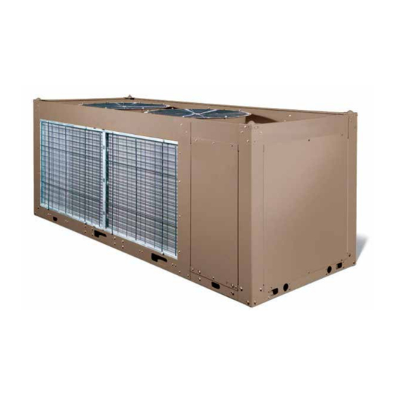
York YCAL Series Start-Up Checklist
60 hz
Hide thumbs
Also See for YCAL Series:
- Manual (105 pages) ,
- Installation operation & maintenance (174 pages)
Advertisement
Quick Links
SERVICE POLICY & PROCEDURES
Commissioning of this unit should only
be carried out by Johnson Controls
Authorized personnel.
Commissioning personnel should be thoroughly familiar
with the information contained in this literature, in ad-
dition to this section.
Perform the commissioning using the detailed checks
outlined in the Equipment Startup Checklist as the com-
missioning procedure is carried out.
PREPARATION – POWER OFF
The following basic checks should be made with the
customer power to the unit switched OFF.
Inspection
Inspect unit for installation damage. If found, take action
and/or repair as appropriate.
Refrigerant Charge
Packaged units are normally shipped as standard with a
full refrigerant operating charge. Check that refrigerant
pressure is present in both systems and that no leaks are
apparent. If no pressure is present, a leak test must be
undertaken, the leak(s) located and repaired. Remote
systems and units are supplied with a nitrogen hold-
ing charge. These systems must be evacuated with a
suitable vacuum pump/recovery unit as appropriate to
below 500 µm.
Do not liquid charge with static water in the cooler.
Care must also be taken to liquid charge slowly to avoid
excessive thermal stress at the charging point. Once the
vacuum is broken, charge into the condenser coils with
the full operating charge.
YCAL0012-0032 60 HZ
START-UP CHECKLIST
Supersedes: 150.66-CL2 (309)
COMMISSIONING
Service and Oil Line Valves
Open each compressor suction, economizer, and dis-
charge service valve. If valves are of the back-seat type,
open them fully (counterclockwise) then close one turn
of the stem to ensure operating pressure is fed to pressure
transducers. Open the liquid line service valve and oil
return line ball valve fully in each system.
Compressor Oil
To add oil to a circuit - connect a YORK hand oil pump
(Part No. 470-10654-000) to the 1/4 in. oil charging
valve on the oil separator piping with a length of clean
hose or copper line, but do not tighten the flare nut. Us-
ing clean oil of the correct type (F oil), pump oil until
all air has been purged from the hose then tighten the
nut. Stroke the oil pump to add oil to the oil system.
The oil level should be between the middle of the lower
and middle of the upper sight glasses of the oil separa-
tor. Approximately 4 gal to 5 gal is present in the each
refrigerant system, with typically 1 gal to 2 gal in each
oil separator. Oil levels in the oil separators above the
top sight glass in either oil separator should be avoided
and may cause excessive oil carryover in the system.
High oil concentration in the system may cause nuisance
trips resulting from incorrect readings on the level sensor
and temperature sensors. Temperature sensor errors may
result in poor liquid control and resultant liquid overfeed
and subsequent damage to the compressor.
Fans
Check that all fans are free to rotate and are not dam-
aged. Ensure blades are at the same height when rotated.
Ensure fan guards are securely fixed.
Isolation / Protection
Verify all sources of electrical supply to the unit are taken
from a single point of isolation. Check that the maximum
recommended fuse sizes given in the Technical Data
Section in IOM (150.66-NM2) has not been exceeded.
Form 150.66-CL2 (820)
Advertisement

Related Manuals for York YCAL Series


Summary of Contents for York YCAL Series
- Page 1 Compressor Oil dition to this section. To add oil to a circuit - connect a YORK hand oil pump (Part No. 470-10654-000) to the 1/4 in. oil charging Perform the commissioning using the detailed checks...
- Page 2 FORM 150.66-CL2 (820) Control Panel Compressor Heaters Check the panel to see that it is free of foreign materials Verify the compressor heaters are energized. If the ambi- (wire, metal chips, or similar materials) and clean out ent temperature is above 96°F (36°C) the compressor if required.
-
Page 3: Equipment Startup Checklist
FORM 150.66-CL2 (820) EQUIPMENT STARTUP CHECKLIST 7. Check the control panel to ensure it is free of JOB NAME: ______________________________ foreign material (wires, metal chips, or similar SALES ORDER #: _________________________ material). LOCATION: ______________________________ 8. Visually inspect wiring (power and control). Wir- ing MUST meet NEC and local codes. - Page 4 FORM 150.66-CL2 (820) The chilled liquid setpoint may need to TABLE 1 – SETPOINTS ENTRY LIST be temporarily lowered to ensure all OPTIONS Display Language compressors cycle “ON.” Sys 1 Switch Chilled Liquid * Ambient Control Local/Remote Mode Control Mode This unit uses scroll compressors Display Units which can only operate in one direc-...
- Page 5 FORM 150.66-CL2 (820) After the subcooling is verified, the suction superheat Ensure that superheat is set at a minimum of 10°F (5.56°C) should be checked. The superheat should be checked only with a single compressor running on each circuit. after steady state operation of the chiller has been estab- lished, the leaving water temperature has been pulled down ...
- Page 6 5000 Renaissance Drive, New Freedom, Pennsylvania USA 17349 1-800-524-1330 Subject to change without notice. Printed in USA Copyright © by Johnson Controls 2020 www.johnsoncontrols.com ALL RIGHTS RESERVED Form 150.66-CL2 (820) Issue Date: August 29, 2020 Supersedes: 150.66-CL2 (309)