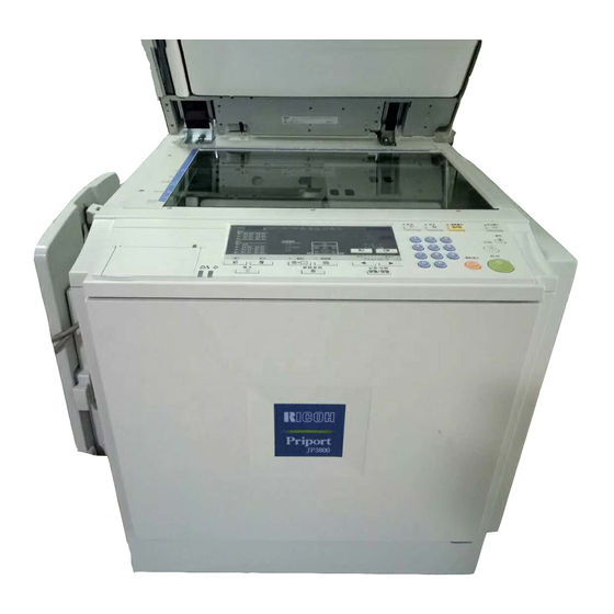
Ricoh JP3000 Service Manual
Machine code c238
Hide thumbs
Also See for JP3000:
- Service manual (693 pages) ,
- Operating instructions manual (128 pages)
Table of Contents
Advertisement
Quick Links
Advertisement
Table of Contents

Related Manuals for Ricoh JP3000


Summary of Contents for Ricoh JP3000
- Page 1 SERVICE MANUAL (Machine code: C238)
- Page 2 IMPORTANT SAFETY NOTICES PREVENTION OF PHYSICAL INJURY 1. Before disassembling or assembling parts of the printer and peripherals, make sure that the power cord is unplugged. 2. The wall outlet should be near the printer and easily accessible. 3. If any adjustment or operation check has to be made with exterior covers off or open while the main switch is turned on, keep hands away from electrified or mechanically driven components.
- Page 3 SAFETY AND ECOLOGICAL NOTES FOR DISPOSAL 1. Dispose of replaced parts in accordance with local regulations. 2. Used ink and masters should be disposed of in an environmentally safe manner and in accordance with local regulations. 3. When keeping used lithium batteries (from the main processing units) in order to dispose of them later, do not store more than 100 batteries (from the main processing units) per sealed box.
-
Page 4: Table Of Contents
TABLE OF CONTENTS 1. INSTALLATION ................1-1 1.1 INSTALLATION REQUIREMENTS ............1-1 1.1.1 OPTIMUM ENVIRONMENTAL CONDITION........1-1 1.1.2 ENVIRONMENTS TO AVOID............1-1 1.1.3 POWER CONNECTION ..............1-1 1.1.4 ACCESS TO THE MACHINE ............1-2 1.2 INSTALLATION PROCEDURE ..............1-3 1.2.1 MAIN BODY ..................1-3 Accessory Check ..................1-3 Installation Procedure ................1-4 1.2.2 PLATEN COVER INSTALLATION (OPTION) ........1-9 Accessory Check ..................1-9... - Page 5 3.3 SCANNER ....................3-4 3.3.1 EXPOSURE GLASS / SCALES............3-4 3.3.2 SBU AND LAMP STABILIZER / SCANNER MOTOR.......3-4 3.3.3 SCANNER H.P. SENSOR / PLATEN COVER SENSOR ....3-5 3.3.4 EXPOSURE LAMP (XENON LAMP) ..........3-6 3.3.5 SCANNER WIRES ................3-7 Installation.....................3-7 3.3.6 IMAGE ADJUSTMENT ..............3-9 3.4 MASTER EJECT ..................3-10 3.4.1 MASTER EJECT UNIT ..............3-10 3.5 MASTER FEED ..................3-11...
- Page 6 4. TROUBLESHOOTING ..............4-1 4.1 ERROR CODES..................4-1 4.2 ELECTRICAL COMPONENT DEFECTS ..........4-3 4.2.1 SENSORS ..................4-3 4.2.2 SWITCHES..................4-4 4.2.3 LINES ....................4-5 4.3 FUSE, LED, VR, DIP-SW, AND TP TABLES ..........4-6 4.3.1 BLOWN FUSE CONDITIONS ............4-6 4.3.2 LED’S ....................4-6 4.3.3 VR’S ....................4-6 4.3.4 DIP SWITCHES................4-7 4.3.5 TEST POINTS ..................4-7 5.
- Page 7 5.8 MAIN MENU NO.7: MEMORY CLEAR............5-13 5.8.1 SP TABLE ..................5-13 5.8.2 SP7: HOW TO CLEAR ..............5-13 5.8.3 SP7-1: FACTORY SETTINGS CLEAR...........5-13 5.9 MAIN MENU NO.8: SYSTEM TEST............5-14 5.9.1 SP TABLE ..................5-14 5.9.2 SP8-1: DOWNLOAD MAIN FIRMWARE ........5-14 5.9.3 SP8-2: UPLOAD MAIN FIRMWARE..........5-15 5.9.4 SP8-10: TEST PATTERNS ............5-15 5.9.5 SP8-21: PAPER FEED TEST (15 RPM).........5-15 5.9.6 SP8-22: FREE RUN PAPER FEED (15 RPM) .......5-15...
- Page 8 6.4.7 FINE MODE..................6-15 6.4.8 THERMAL HEAD................6-16 Specifications..................6-16 Thermal head control ................6-16 Thermal head protection ..............6-16 Remarks for Handling the Thermal Head..........6-17 6.5 MASTER FEED ..................6-18 6.5.1 OVERVIEW ..................6-18 Procedure ...................6-18 6.5.2 MASTER FEED MECHANISM ............6-19 Mechanism ..................6-19 Procedure ...................6-19 Notes ....................6-19 6.5.3 CLAMPER AND TENSION ROLLER MECHANISM.......6-20 Mechanism ..................6-20 Notes ....................6-20...
- Page 9 6.7.7 PAPER TABLE MECHANISM ............6-33 Table lifting/lowering ................6-33 Mechanism ..................6-33 Notes ....................6-33 Paper end detection................6-33 Paper size detection ................6-33 Table side fences and side-to-side shift..........6-34 Side fence friction pads...............6-34 6.8 PAPER DELIVERY..................6-35 6.8.1 OVERVIEW ..................6-35 6.8.2 PAPER DELIVERY UNIT DRIVE MECHANISM......6-35 Mechanism ..................6-35 Notes ....................6-35 6.8.3 PAPER SEPARATION FROM THE DRUM ........6-36...
- Page 10 SPECIFICATIONS..............SPEC-1 1. GENERAL SPECIFICATIONS............. SPEC-1 DOCUMENT FEEDER (C600) 1. OVERALL INFORMATION ........... C600-1 1.1 SPECIFICATIONS................C600-1 1.2 MECHANICAL COMPONENT LAYOUT ..........C600-2 1.3 ELECTRICAL COMPONENT LAYOUT..........C600-3 1.4 ELECTRICAL COMPONENT DESCRIPTION........C600-4 1.5 DRIVE LAYOUT ................. C600-5 2. DETAILED SECTION DESCRIPTIONS ........ C600-6 2.1 ORIGINAL SIZE DETECTION............
-
Page 11: Installation
31 October 2001 INSTALLATION REQUIREMENTS 1. INSTALLATION 1.1 INSTALLATION REQUIREMENTS Carefully select the installation location because environmental conditions greatly affect machine performance. 1.1.1 OPTIMUM ENVIRONMENTAL CONDITION 1. Temperature 10 to 30 °C (50 to 86 °F) 2. Humidity 20 to 90 % RH 3. -
Page 12: Access To The Machine
INSTALLATION REQUIREMENTS 31 October 2001 1.1.4 ACCESS TO THE MACHINE Place the machine near a power source, providing clearance as shown below. C238I000.WMF... -
Page 13: Installation Procedure
Make sure that you have all the accessories listed below: Description Quantity 1. Master Spool................2 2. Paper Feed Side Pad ..............2 3. Operating Instructions..............1 4. NECR (Ricoh version only) ............1 5. Model Name Plates (C238-22, -52 and -54 only)....... 1 set... - Page 14 INSTALLATION PROCEDURE 31 October 2001 Installation Procedure C238I014.WMF 1. Unpack the box. When installing the optional table, mount the machine as shown (there are 2 screws [A] packed with the table). CAUTION Only lift with the carrying handles on the bottom corners of the machine. Secure the machine on the table with the 2 screws [A] provided.
- Page 15 31 October 2001 INSTALLATION PROCEDURE C238I016.WMF C238I017.WMF C238I020.WMF 2. Remove the filament tape and string securing the covers and units as shown above.
-
Page 16: Installation Procedure
INSTALLATION PROCEDURE 31 October 2001 3. Pull out the master making unit, and take out the accessory bag [A]. C238I038.WMF 4. Insert both spools into a new master roll. C238I030.WMF 5. Install the master roll as shown to the right. C238I032.WMF 6. - Page 17 31 October 2001 INSTALLATION PROCEDURE 7. Close the cover [C] using both hands. 8. Set the master making unit. C238I031.WMF 9. Open the door, and insert a new ink cartridge [D]. C238I034.WMF 10. Open the paper table, and load a stack of paper .
- Page 18 INSTALLATION PROCEDURE 31 October 2001 12. Raise the paper delivery table [G] slightly, then gently lower it. 13. Lift the side plates and the end plate, and adjust them to the paper size. C238I027.WMF 14. Firmly insert the power plug in the outlet.
-
Page 19: Platen Cover Installation (Option)
31 October 2001 INSTALLATION PROCEDURE 1.2.2 PLATEN COVER INSTALLATION (OPTION) Accessory Check Check the quantity and condition of the accessories in the box against the following list: Description Quantity 1. Stepped Screw................2 Installation Procedure C238I001.WMF 1. Install the platen cover [A] (2 screws). -
Page 20: Adf Installation (Option)
INSTALLATION PROCEDURE 31 October 2001 1.2.3 ADF INSTALLATION (OPTION) Accessory Check Check the quantity and condition of the accessories in the box against the following list: Description Quantity 1. Stepped Screw ................2 2. Screws ..................3 3. Screwdriver................1 4. -
Page 21: Installation Procedure
31 October 2001 INSTALLATION PROCEDURE Installation Procedure C238I002.WMF 1. Remove the strips of tape. 1-11... - Page 22 INSTALLATION PROCEDURE 31 October 2001 C238I003.WMF C238I004.WMF 2. Remove the left scale [A] (2 screws). 3. Place the DF exposure glass [B] on the glass holder. NOTE: When installing the DF exposure glass, make sure that the white point [C] is positioned at the lower front side, as shown. 4.
- Page 23 31 October 2001 INSTALLATION PROCEDURE C238I018.WMF 8. Connect the cables [I] and [J] to the main body. C238I500.WMF 9. Attach the scale decal [K] as shown. 10. Plug in the power cord, then turn the main switch on. 11. Make a full size copy using the ADF. Then check to make sure the side-to-side and leading edge registrations are correct.
-
Page 24: Adf Stabilizer Installation
INSTALLATION PROCEDURE 31 October 2001 ADF stabilizer installation C238I040.WMF 1. Attach the two stabilizer brackets [A] to the back of the table using the thumbscrews (4 screws). 2. Attach the caution label [B], as shown. CAUTION This procedure must be done to prevent the machine from falling backwards when the ADF is open. -
Page 25: Tape Marker (Option)
31 October 2001 INSTALLATION PROCEDURE 1.2.4 TAPE MARKER (OPTION) Accessory Check Check the quantity and condition of the accessories in the box against the following list: Description Quantity 1. Knob Screw (C210, C217, C218, C219, C222, C223, C225, C228, C238, C237, and C238 only)........2 2. -
Page 26: Installation Procedure
INSTALLATION PROCEDURE 31 October 2001 Installation Procedure - For C238 - C238I536.WMF C238I006.WMF 1. Turn off the main switch and unplug the power cord. 2. Remove the paper delivery plate (4 screws). 3. Cut the cap [A] off the rear cover of the main body with pliers, then connect the tape marker cable to the main body. -
Page 27: For C231 And C237
31 October 2001 INSTALLATION PROCEDURE - For C231 and C237- C238I536.WMF C238I533.WMF 1. Turn off the main switch and unplug the power cord. 2. Remove the paper delivery table (2 screws). 3. Remove the paper delivery plate (4 screws). 4. Cut the cap [A] off the rear cover with pliers, then connect the tape marker cable to the main body. -
Page 28: For C226
INSTALLATION PROCEDURE 31 October 2001 - For C226 - C238I516.PCX C238I517.WMF Main Body: 1. Turn off the main switch and unplug the power cord. 2. Remove the rear cover (6 screws). 3. Replace the screw [A], to secure the AC drive board with M4 x 25 screws (accessories). -
Page 29: For C210, C218, C219, C222, And C223
31 October 2001 INSTALLATION PROCEDURE - For C210, C218, C219, C222, and C223 - C238I502.PCX 1. Turn off the main switch and unplug the power cord. 2. Install the tape marker on the main body with two knob screws [A] (accessories) in the two outer holes in the tape marker bracket. -
Page 30: For C217 And C225
INSTALLATION PROCEDURE 31 October 2001 - For C217 and C225 - C238I503.PCX 1. Turn off the main switch and unplug the power cord. 2. Install the tape marker on the main body with two knob screws [A] (accessories) in the two inner holes of the tape marker bracket. NOTE: 1) Tighten the knob screws with a screwdriver to prevent them from coming loose. -
Page 31: Common Steps
31 October 2001 INSTALLATION PROCEDURE - Common Steps - 1. Remove the small cap in the rear cover of the main body [A]. Then, connect the tape marker cable [B] to the main body, and install the connector cover [C] using one of the rear cover securing screws. -
Page 32: Additional Drums (Option)
INSTALLATION PROCEDURE 31 October 2001 1.2.5 ADDITIONAL DRUMS (OPTION) C238I020.WMF C238I534.WMF There are two types of drum units: A3 Size: Color drum A4 Size: Black drum (Black ink only) 1. Remove the protective sheet [A] and the lock [B] from the drum unit. 2. -
Page 33: Interface Board (Option)
31 October 2001 INSTALLATION PROCEDURE 1.2.6 INTERFACE BOARD (OPTION) Accessory Check Check the quantity and condition of the accessories in the box against the following list: Description Quantity 1. Interface Board ..............1 2. Interface Cable ..............1 3. Screw M3 x 6 ............... 2 4. -
Page 34: Preventive Maintenance
31 October 2001 MAINTENANCE TABLE 2. PREVENTIVE MAINTENANCE 2.1 MAINTENANCE TABLE The following items should be maintained periodically. There are two sets of intervals - one based on time and the other based on print count. For maintenance items with entries in both of them, use whichever comes first. C: Clean, R: Replace, L: Lubricate, A: Adjust Interval Time... - Page 35 MAINTENANCE TABLE 31 October 2001 Interval Time Print Counter NOTE Item 2M 2.4M 3M 1M 1.2M Drum and Ink Supply Cloth Screen Ink Roller One-way ☛ 3.8.5 Clutch Drum Drive Gears Grease and Cam [D] (Alvania Ink Pump Gears [E] Motor Oil (SAE #20) In/Outside of Drum...
-
Page 36: Replacement And Adjustment
31 October 2001 GENERAL CAUTION 3. REPLACEMENT AND ADJUSTMENT 3.1 GENERAL CAUTION CAUTION Turn off the main power switch and unplug the machine before attempting any of the procedures in this section. NOTE: This manual uses several symbols. The meaning of those symbols are as follows: ☛... -
Page 37: Rear Covers
COVERS / BOARDS 31 October 2001 3.2.2 REAR COVERS C238R007.WMF [A]: Rear left cover (! x 5) [B]: Rear right cover (! x 3) [C]: Upper left cover (! x 2) [D]: Rear upper cover 3.2.3 MPU C238R008.WMF • Rear left cover, Rear right cover (☛ 3.2.2) [A]: MPU ("... -
Page 38: Psu
31 October 2001 COVERS / BOARDS 3.2.4 PSU C238R009.WMF • Upper left cover (☛ 3.2.2) • Master eject unit (☛ 3.4.1) [A]: PSU (" x 5, ! x 2, 2 clamps) CAUTION: When the PSU is replaced, the thermal head voltage returns to the default. -
Page 39: Scanner
SCANNER 31 October 2001 3.3 SCANNER 3.3.1 EXPOSURE GLASS / SCALES [A]: Left scale (! x 2) [B]: Upper scale (! x 3) [C]: Exposure glass C238R038.WMF 3.3.2 SBU AND LAMP STABILIZER / SCANNER MOTOR • Left scale, Upper scale, Exposure glass (☛... -
Page 40: Scanner H.p. Sensor / Platen Cover Sensor
31 October 2001 SCANNER [C]: Lamp stabilizer (" x 2, ! x 5) C238R041.WMF [D]: Scanner motor (! x 2, 1 spring) C238R042.WMF 3.3.3 SCANNER H.P. SENSOR / PLATEN COVER SENSOR • Left scale, Upper scale, Exposure glass (☛ 3.3.1) •... -
Page 41: Exposure Lamp (Xenon Lamp)
SCANNER 31 October 2001 3.3.4 EXPOSURE LAMP (XENON LAMP) C238R044.WMF • Move the first scanner next to the opening in the frame. • Exposure glass (☛ 3.3.1) • [1]: Left stay (☛ 3.3.3) [A]: Platen base (" x 1, ! x 5) [B]: Rear frame ("... -
Page 42: Scanner Wires
31 October 2001 SCANNER 3.3.5 SCANNER WIRES • Move the first scanner next to the opening in the frame. • Exposure glass (☛ 3.3.1) • SBU cover (☛ 3.3.2) • Left stay (☛ 3.3.3) • Rear and front frames (☛ 3.3.4) C238R029.WMF C238R046.WMF 1. - Page 43 SCANNER 31 October 2001 C238R047.WMF C238R048.WMF 8. Secure the first scanner with the pins [E]. 9. Tighten the screw securing the tension bracket [F]. 10. Secure the scanner drive pulley [G] (1 Allen screw). 11. Remove the scanner positioning pins [I] (P/N: #A0069104). 12.
-
Page 44: Image Adjustment
31 October 2001 SCANNER 3.3.6 IMAGE ADJUSTMENT Purpose: To adjust the image position on prints by changing the SP settings. Adjust the following in the order given below. SP6-10: Master writing speed (☛ 5.7.3) ↓ SP6-21: Paper registration position (☛ 5.7.3) ↓... -
Page 45: Master Eject
MASTER EJECT 31 October 2001 3.4 MASTER EJECT 3.4.1 MASTER EJECT UNIT C238R025.WMF [A]: Master eject unit (" x 3, ! x 2, 1 clamp) 3-10... -
Page 46: Master Feed
31 October 2001 MASTER FEED 3.5 MASTER FEED 3.5.1 MASTER MAKING UNIT C238R010.WMF [A]: Master making unit (! x 2) 3.5.2 THERMAL HEAD C238R049.WMF • Master making unit (☛ 3.5.1) • Open the platen roller unit [1]. [A]: T/H upper cover (! x 2) [B]: T/H side cover (! x 1) 3-11... -
Page 47: Installation
MASTER FEED 31 October 2001 • Close the platen roller unit [1]. [C]: Thermal head (" x 2) C238R050.WMF Installation C238R030.WMF If the following remarks are not followed, the thermal head will be installed incorrectly. 1) Fit the base’s springs [D] over the protrusions [E] on the underside of the thermal head (6 points). -
Page 48: Thermal Head Voltage Adjustment
31 October 2001 MASTER FEED 3.5.3 THERMAL HEAD VOLTAGE ADJUSTMENT CAUTION This adjustment is always required when the thermal head or PSU has been replaced. Purpose: To maintain master making quality and extend the lifetime of the thermal head. Standard: Refer to the voltage value (X) printed on the thermal head. The value varies from one thermal head to another. -
Page 49: Master End Sensor Adjustment
MASTER FEED 31 October 2001 3.5.4 MASTER END SENSOR ADJUSTMENT Purpose: To ensure that the sensor detects the end mark (a solid black area) on the master roll. Standard: 1.6 volts (within “+0.1” and “-0” volts) Tools: Circuit tester, the core of a used master roll (the core has no master) C238R021.WMF C238R011.WMF •... -
Page 50: Paper Feed
31 October 2001 PAPER FEED 3.6 PAPER FEED 3.6.1 PICK-UP ROLLER / PAPER FEED ROLLER / FRICTION PAD C238R024.WMF • Lower the paper table. [A]: Pick-up roller ($ x 1) [B]: Paper guide [C]: Feed roller ($ x 1) [D]: Friction pad 3.6.2 PAPER SEPARATION PRESSURE ADJUSTMENT Purpose: To ensure that the friction pad exerts sufficient pressure for smooth... -
Page 51: Paper Width Detection Board
PAPER FEED 31 October 2001 3.6.3 PAPER WIDTH DETECTION BOARD C238R018.WMF C238R019.WMF C238R020.WMF • Lower the paper table. [A]: Paper table (" x 1, # x 2) [B]: Table cover (! x 5, 3 washers) [C]: Sensor cover (! x 2) [D]: Paper width detection board ("... -
Page 52: Printing
31 October 2001 PRINTING 3.7 PRINTING 3.7.1 PRESS ROLLER C238R037.WMF CAUTION Take care to avoid possible injury. If the printing pressure release arms disengage, the press roller will be pulled upwards suddenly. • Remove the drum. [A]: Press roller (! x 1) The bearings on the rear and front differ. -
Page 53: Press Roller Release Lever Adjustment
PRINTING 31 October 2001 3.7.2 PRESS ROLLER RELEASE LEVER ADJUSTMENT Purpose: To maintain the correct clearance between the press roller arms and press roller lock levers. This ensures that the press roller is correctly released and pressed against the drum when the press roller release solenoid is energized. Standard: 0.7 to 1.2 mm Tools: A thickness gauge C238R001.WMF... -
Page 54: Printing Pressure Adjustment
31 October 2001 PRINTING 3.7.3 PRINTING PRESSURE ADJUSTMENT Purpose: To make better print results without decreasing the run length. Standard: Within 10 ± 0.2 mm C238R052.WMF • Paper delivery unit (☛ 3.9.1) 1. Adjust the distance [A] to 10 ± 0.2 mm by turning the adjusting bolt [B]. 2. -
Page 55: Drum
DRUM 31 October 2001 3.8 DRUM 3.8.1 PREPARATION Before attempting any of the procedures in this section, wipe off the ink around the ink roller. To do this, set SP2-10 (ink detection) to OFF, and feed paper until ink ends. After finishing the required procedures in this section, do not forget to return SP2- 10 to the default (ink detection on). -
Page 56: Installation
31 October 2001 DRUM Installation Inside C238R056.WMF Outside C238R055.WMF C238R057.WMF • Do not scratch the cloth screen or metal screen. • Properly insert the edge of the mylar [A] on the cloth screen under the mylar [B] on the metal screen, as shown above. Otherwise, ink will leak from the trailing edge of the master on the drum during a long printing run. -
Page 57: Clamper / Metal Screen
DRUM 31 October 2001 3.8.3 CLAMPER / METAL SCREEN C238R058.WMF C238R002.WMF • Remove the drum • Cloth screen (☛ 3.8.2) [A]: Clamper lever (1 hexagon screw) [B]: Clamper - open the clamping plate [C], then remove the clamper. NOTE: 1) Do not allow ink to get on the inside of the clamping plate [C]. If it is dirty with ink, the master may slip off and the image position on the prints will move toward the trailing edge of the prints during a printing run. -
Page 58: Installation
31 October 2001 DRUM Installation C238R059.WMF • Make sure that the correct end of the metal screen is overlapping. (The right side overlaps, as viewed from the non-operation side, as shown above.) • The 4 screws holding the drum master clamper are longer than the 12 screws holding the metal screen, although they are similar in appearance. -
Page 59: Ink Pump Adjustment
DRUM 31 October 2001 3.8.4 INK PUMP ADJUSTMENT Purpose: To ensure the smooth operation of the ink pump plunger by properly positioning its holder. C238R014.WMF • Remove the drum [A]: Lower pump cover (! x 2) [B]: Upper pump cover (! x 3) C238R015.WMF 1. - Page 60 31 October 2001 DRUM C238R016.WMF 4. Check that the piston motion is smooth. 5. If the motion is stiff, loosen the pump screws [G] and adjust the pump position. 6. After tightening, repeat step 4 and step 3. C238R017.WMF 7. Re-tighten the two screws [H]. 8.
-
Page 61: Ink Roller Unit / Ink Roller One-Way Clutch
DRUM 31 October 2001 3.8.5 INK ROLLER UNIT / INK ROLLER ONE-WAY CLUTCH • Metal screen (☛ 3.8.3) • Pump covers (☛ 3.8.4) [A]: Board cover (! x 2) [B]: Front stay (" x 2, ! x 3) [C]: Front flange C238R023.WMF [D]: Rear stay (! x 2) [E]: Rear stoppers (! x 1) -
Page 62: Doctor Roller Gap Adjustment
31 October 2001 DRUM 3.8.6 DOCTOR ROLLER GAP ADJUSTMENT Purpose: To control the ink thickness around the ink roller. Standard: 0.08 mm gauge passes, 0.10 mm gauge does not. Tools: Thickness gauge CAUTION: Normally the doctor roller gap is not adjusted or changed. It tends to be difficult to change in the field. -
Page 63: Ink Detection Adjustment
DRUM 31 October 2001 3.8.7 INK DETECTION ADJUSTMENT Purpose: To ensure that the CPU detects a no-ink condition. CAUTION: Before attempting this procedure, wipe off the ink around the ink roller. To do this, set SP2-10 (ink detection) to OFF, and feed paper until ink ends. -
Page 64: Paper Delivery
31 October 2001 PAPER DELIVERY 3.9 PAPER DELIVERY 3.9.1 PAPER DELIVERY UNIT [A]: Paper delivery cover (! x 4) [B]: Paper delivery unit (" x 3, ! x C238R027.WMF 3.9.2 DELIVERY BELT / PAPER EXIT SENSOR C238R035.WMF • Paper delivery unit (☛ 3.9.1) [A]: Paper guide (! x 2) [B]: Delivery belts [C]: Vacuum fan motor ("... -
Page 65: Exit Pawl Adjustment
PAPER DELIVERY 31 October 2001 3.9.3 EXIT PAWL ADJUSTMENT Purpose: To ensure that the exit pawls can move out of the way of the drum master clamper while the drum is rotating. Clearance adjustment Standard: Within 1.15 ± 0.15 mm C238R061.WMF C238R034.WMF •... -
Page 66: Timing Adjustment
31 October 2001 PAPER DELIVERY Timing adjustment Standard: 0 or less than 0.5 mm C238R005.WMF C238R022.WMF • Front cover (☛ 3.2.1) • Rear covers (☛ 3.2.2) • Do this after the clearance adjustment. 1. Turn the drum manually until the recess in the drum drive gear meets the positioning hole [A] in the bracket, as shown. -
Page 67: Air Pump Adjustment
PAPER DELIVERY 31 October 2001 3.9.4 AIR PUMP ADJUSTMENT Purpose: To ensure that the exit pawl produces a jet of air at the proper time. C238R028.WMF C238R026.WMF • Rear covers (☛ 3.2.2) 1. Check the recess in the drum drive gear meets the positioning hole [A] in the bracket, as shown. -
Page 68: Special Tools
31 October 2001 SPECIAL TOOLS 3.10 SPECIAL TOOLS The following are the special tools used for service. Description Part number Note ☛ 3.3.5 Scanner positioning pins (4 pins as a set) A006 9104 ☛ 5.9.2 Flash memory card A230 9352 ☛... -
Page 69: Troubleshooting
31 October 2001 ERROR CODES 4. TROUBLESHOOTING 4.1 ERROR CODES Symptom Possible cause E-00 Clamper error Clamper drive The MPU cannot detect the clamper position sensor Clamper sensors signal (open or closed) within 3.0 seconds after the Clamper motor clamper motor turns on. E-01 Cutter error Cutter drive... - Page 70 ERROR CODES 31 October 2001 Symptom Possible cause E-21 Paper Exit Timing Sensor error Drum sensors The paper exit timing sensor does not activate before the Feeler master eject position sensor activates. E-22 2nd Feed Timing Sensor error Drum sensors The 2nd feed timing sensor does not activate before the Feeler paper exit timing sensor activates.
-
Page 71: Electrical Component Defects
31 October 2001 ELECTRICAL COMPONENT DEFECTS 4.2 ELECTRICAL COMPONENT DEFECTS C238T001.WMF 4.2.1 SENSORS Component Condition Symptom Master Eject Position (HP) Open E-23 is displayed whenever the drum rotates. Sensor Shorted Paper Exit Timing Sensor Open E-21 is displayed whenever the drum rotates. Shorted Feed Start Timing Sensor Open... -
Page 72: Switches
ELECTRICAL COMPONENT DEFECTS 31 October 2001 Component Condition Symptom Master Set Cover Sensor The “D” jam indicator is lit or E-01 is displayed Open whenever the cover isn’t placed correctly. Shorted The “the open cover” and “D” indicators are lit. Master End Sensor Master making can start even if there is no White... -
Page 73: Lines
31 October 2001 ELECTRICAL COMPONENT DEFECTS 4.2.3 LINES Component Condition Symptom +5v (CN102-4) Wire (or PSU) The machine does not turn on. broken +5v (CN102-2, 3) The machine does not turn on, but LED104 on the MPU blinks. +12v (CN102-9) The thermal head does not burn the master. -
Page 74: Fuse, Led, Vr, Dip-Sw, And Tp Tables
FUSE, LED, VR, DIP-SW, AND TP TABLES 31 October 2001 4.3 FUSE, LED, VR, DIP-SW, AND TP TABLES 4.3.1 BLOWN FUSE CONDITIONS Main motor board Rate Symptom Fuse 10.0 A The “close the covers” indicator is lit. Rate Symptom FU700 6.3 A The machine does not turn on. -
Page 75: Dip Switches
31 October 2001 FUSE, LED, VR, DIP-SW, AND TP TABLES Ink detection board Function ☛5.7.2) Adjusts the ink detection. ( 4.3.4 DIP SWITCHES Ink detection board Normal drum Color drum A4 black drum 4.3.5 TEST POINTS Function ☛3.5.4) TP102 Measures the master end sensor voltage. ( Function ☛3.5.3) TP701... -
Page 76: Service Tables
31 October 2001 USING SERVICE PROGRAM MODES 5. .SERVICE TABLES 5.1 USING SERVICE PROGRAM MODES Use the service program modes (SP modes) to check electrical data, change operating modes, and adjust values. 5.1.1 ACCESSING SP MODES Entering SP Mode 1. Key in the following sequence. Method 1: ! →... -
Page 77: How To Select A Program Number
USING SERVICE PROGRAM MODES 31 October 2001 5.1.2 HOW TO SELECT A PROGRAM NUMBER C238S002.WMF [A]: Zoom counter: Main menu number [B]: Class counter: Sub menu number [C]: Paper counter: Setting 1. Using the number keys [D] or the C238S006.WMF scroll keys [E], enter the desired main menu number (listed below), then press the Enter key. -
Page 78: Main Menu No.1: Copy Data
31 October 2001 MAIN MENU NO.1: COPY DATA 5.2 MAIN MENU NO.1: COPY DATA 5.2.1 SP TABLE Menu Items Function 1-1 Total master counter 1-2 Master counter - ADF 1-3 Master counter - Letter mode 1-4 Master counter - Letter/Photo mode 1-5 Master counter - Photo mode 1-6 Master counter - Tint mode 1-7 Master counter - Economy mode... -
Page 79: Sp1-70, 71: Firmware/Rom Suffix Information
MAIN MENU NO.1: COPY DATA 31 October 2001 5.2.2 SP1-70, 71: FIRMWARE/ROM SUFFIX INFORMATION This model has no LCD, so the suffix is displayed as shown below instead of in English letters. C238S012.WMF NOTE: The letters “i” and “o” are always skipped. 5.2.3 SP1-80: ERROR CODE INFORMATION Purpose: To display the error codes and the date. -
Page 80: Main Menu No.2: Basic Settings
31 October 2001 MAIN MENU NO.2: BASIC SETTINGS 5.3 MAIN MENU NO.2: BASIC SETTINGS 5.3.1 SP TABLE Menu Items Default Settings 2-1 Default print speed 1 to 5 2-2 Default image position 1 to 7 1: -15mm, 2: -10mm, 3: -5mm, 4: 0.0mm, 5: +5mm, 6: +10mm, 7: +15mm 2-10 Ink detection board... -
Page 81: Main Menu No.3: System Settings
MAIN MENU NO.3: SYSTEM SETTINGS 31 October 2001 5.4 MAIN MENU NO.3: SYSTEM SETTINGS 5.4.1 SP TABLE Menu Items Default Settings ☛ 5.4.2 3-1 Input the present time 3-10 Optional key counter setting Off/On 5.4.2 SP3-1: INPUT THE PRESENT TIME Input the year, the month / date, and the time in that order. -
Page 82: Main Menu No.4: Input Mode
31 October 2001 MAIN MENU NO.4: INPUT MODE 5.5 MAIN MENU NO.4: INPUT MODE 5.5.1 SP TABLE Menu Items Menu Items 4-1 Scanner HP sensor 4-41 Registration sensor 4-2 Platen cover sensor 4-42 Feed start timing sensor 4-43 2nd feed timing sensor 4-10 Master making unit set switch 4-44 Paper exit sensor 4-11 Master set cover sensor... -
Page 83: Main Menu No.5: Output Mode
MAIN MENU NO.5: OUTPUT MODE 31 October 2001 5.6 MAIN MENU NO.5: OUTPUT MODE 5.6.1 SP TABLE Menu Items Menu Items 5-1 Exposure lamp (xenon lamp) 5-30 Table motor - up 5-2 Scanner motor 5-31 Table motor - down 5-32 Paper feed motor: 15 rpm 5-10 Master feed motor 5-33 Paper feed motor: 30 rpm 5-11 Cutter motor... -
Page 84: Main Menu No.6: Adjustment
31 October 2001 MAIN MENU NO.6: ADJUSTMENT 5.7 MAIN MENU NO.6: ADJUSTMENT 5.7.1 SP TABLE Menu Items Default Settings 6-1 Main-scan position – platen mode – -5.0 to 5.0 mm (☛ 5.7.3) 6-2 Main-scan position - ADF mode -5.0 to 5.0 mm (☛ 5.7.3) 6-3 Scanning start position - platen mode –... -
Page 85: Image Adjustment (Sp6-10, -21, -5, -3, And -1)
MAIN MENU NO.6: ADJUSTMENT 31 October 2001 5.7.3 IMAGE ADJUSTMENT (SP6-10, -21, -5, -3, AND -1) Purpose: To adjust the image position on prints by changing the SP settings. Adjust the following in the given order. When correcting errors made when printing with the controller, use only the first two procedures. -
Page 86: Sp6-05: Scanning Speed - Platen
31 October 2001 MAIN MENU NO.6: ADJUSTMENT SP6-05: Scanning speed - platen SP6-06: Scanning speed - ADF 1. Make copies of the test pattern printed during the previous adjustments (☛ previous page), in platen mode at 90 rpm (speed 3). Use the 10th print for the adjustment. -
Page 87: Sp6-31: Sbu Calibration
MAIN MENU NO.6: ADJUSTMENT 31 October 2001 5.7.4 SP6-31: SBU CALIBRATION Purpose: To adjust the SBU after the MPU or the white plate located behind the original scale is replaced. 1. Place a stack of 10 sheets of paper on the exposure glass. 2. -
Page 88: Main Menu No.7: Memory Clear
31 October 2001 MAIN MENU NO.7: MEMORY CLEAR 5.8 MAIN MENU NO.7: MEMORY CLEAR 5.8.1 SP TABLE Menu Items Default Settings 7-1 Factory settings clear No / Clr (☛ 5.8.3) 7-2 All settings clear No / Clr 7-3 Total counter clear No / Clr 7-4 Jam/Error data clear No / Clr... -
Page 89: Main Menu No.8: System Test
MAIN MENU NO.8: SYSTEM TEST 31 October 2001 5.9 MAIN MENU NO.8: SYSTEM TEST 5.9.1 SP TABLE Menu Items Default Settings 8-1 Download main firmware No/Ld (☛ 5.9.2) 8-2 Upload main firmware No/Ld (☛ 5.9.3) 8-10 Test patterns 1 to 9 (☛ 5.9.4) 8-20 Free run - scanner Off/On 8-21 Paper feed (15 rpm) -
Page 90: Sp8-2: Upload Main Firmware
31 October 2001 MAIN MENU NO.8: SYSTEM TEST 5.9.3 SP8-2: UPLOAD MAIN FIRMWARE Purpose: This writes firmware to a flash memory card (P/N’ #A2309352)from the machine. 1. Refer to steps 3 to 5 of section 5.9.2. 2. Connect the power cord, then turn on the main switch while holding the Clear modes key. -
Page 91: Detailed Section Descriptions
31 October 2001 MECHANISM OVERVIEW 6. DETAILED SECTION DESCRIPTIONS The scanning and image processing sections are almost the same as Sapphire (C235). The other sections are almost the same as Silver/Silver-V (C231/C237). 6.1 MECHANISM OVERVIEW 6.1.1 MAJOR PARTS 29 30 C238D001.WMF 1. -
Page 92: Electrical Component Layout
MECHANISM OVERVIEW 31 October 2001 6.1.2 ELECTRICAL COMPONENT LAYOUT C238D003.WMF C238D004.WMF... -
Page 93: Boards
31 October 2001 MECHANISM OVERVIEW Boards Component Function Main Processing Unit (MPU) Controls all machine functions, both directly and through other boards. Lamp Stabilizer This supplies power to the exposure lamp. Power Supply Unit (PSU) Provides dc power to the machine. Operation Panel Boards These boards control the operation panel. -
Page 94: Switches
MECHANISM OVERVIEW 31 October 2001 Switches Component Function Table Lowering Switch Lowers the paper table. Door Safety Switch Checks whether the front door is properly closed. Main Switch Turns the power on or off. Master Making Unit Set Switch Checks if the master making unit is installed. Eject Box Set Switch Checks if the master eject box is installed. -
Page 95: Solenoids
31 October 2001 MECHANISM OVERVIEW Solenoids Component Function Rear Pressure Release Releases the press roller to apply printing Solenoid pressure. Front Pressure Release Releases the press roller to apply printing Solenoid pressure. Counters Component Function Paper Counter Keeps track of the total number of copies. Master Counter Keeps track of the total number of masters made. -
Page 96: Drive Layout
MECHANISM OVERVIEW 31 October 2001 6.1.3 DRIVE LAYOUT C238D002.WMF 1. Pressure plate motor 6. Table motor 2. Clamper motor 7. Paper feed motor 3. Paper delivery motor 8. Master feed motor 4. Main motor 9. Scanner motor 5. Registration motor... -
Page 97: Master Eject Unit
31 October 2001 MASTER EJECT UNIT 6.2 MASTER EJECT UNIT 6.2.1 OVERVIEW C238D022.WMF Overview The master eject unit removes the used master from the drum. (☛ !: Digital Duplicators – Duplicating Process – Master Ejecting) Procedure The drum turns to the master eject position. Then the clamper [A] opens. ↓... -
Page 98: Master Clamper Opening Mechanism
MASTER EJECT UNIT 31 October 2001 6.2.2 MASTER CLAMPER OPENING MECHANISM C238D007.WMF Clamper Mechanism Clamper motor [A] - opens the clamper at the master eject position ↓ Gears [B] ↓ Link [C] ↓ Drum guide [D] - moves and engages the pin on the rear flange of the drum ↓... -
Page 99: Master Eject Roller Mechanism
31 October 2001 MASTER EJECT UNIT 6.2.3 MASTER EJECT ROLLER MECHANISM C238D047.WMF Mechanism Master eject motor [A] ↓ Belt [B] ↓ Gears [C] ↓ Master eject rollers [D] – the upper roller has paddles ↓ Pick up the master and feed it into the master eject box Procedure 1. -
Page 100: Pressure Plate Mechanism
MASTER EJECT UNIT 31 October 2001 6.2.4 PRESSURE PLATE MECHANISM C238D017.WMF Mechanism Pressure plate motor [A] ↓ Gears [B] ↓ Pressure plate rotates ↓ Compresses the masters Procedure 1. After the master has been ejected and the drum is stopped at the master feed position, the pressure plate motor turns until the actuator on the pressure plate actuates the limit sensor [D]. -
Page 101: Scanner Unit
31 October 2001 SCANNER UNIT 6.3 SCANNER UNIT 6.3.1 OVERVIEW C238D050.WMF [A]: Exposure lamp [B]: Charge coupled device (CCD) [C]: First mirror [D]: Second mirror [E]: Third mirror [F]: Lens • The exposure lamp is a xenon lamp (DC 24V). •... -
Page 102: Scanner Drive
SCANNER UNIT 31 October 2001 6.3.2 SCANNER DRIVE C238D051.WMF A: Scanner motor ↓ B: Timing belt ↓ C: Scanner wire ↓ D: First scanner, E: Second scanner Full size mode • During scanning, the first scanner speed is 20.32 mm/s. •... -
Page 103: Image Processing
31 October 2001 IMAGE PROCESSING 6.4 IMAGE PROCESSING 6.4.1 OVERVIEW C238D006.WMF • The CCD line has 7,450 pixels and the resolution is 600 dpi (23.6 lines/mm). • The A/D converter in the SBU transforms the analog signals into 8-bit digital signals. -
Page 104: Auto Background Correction
IMAGE PROCESSING 31 October 2001 6.4.2 AUTO BACKGROUND CORRECTION C238D043.WMF • Auto background correction prevents the background of an original from appearing on copies. • The density of the area [A] (the central 75 mm of the main scan) is the peak white level density. -
Page 105: Binary Processing
31 October 2001 IMAGE PROCESSING 6.4.6 BINARY PROCESSING This process converts the video signal from 8-bit to 1-bit (black and white) in accordance with a threshold value. The threshold value depends on a compensation curve (gamma curve) which corresponds to selected image processing settings. For example, if a darker image is selected, a compensation curve that converts each pixel value to a higher number is selected. -
Page 106: Thermal Head
IMAGE PROCESSING 31 October 2001 6.4.8 THERMAL HEAD Specifications Length: 292.032 mm Number of thermal head elements: 3456 dots Density of thermal head elements: 300 dpi Thermal head control The thermal head contains heating elements at a density of 300 dpi. The thermal heating elements melt the over-coating and polyester film layers of the master, in accordance with the image signal for each pixel. -
Page 107: Remarks For Handling The Thermal Head
31 October 2001 IMAGE PROCESSING Remarks for Handling the Thermal Head Pay careful attention to the following remarks when servicing: • Do not touch the surface • Remove any foreign materials with bare hands. If this Platen from the platen roller. Roller occurs, clean the surface with alcohol. -
Page 108: Master Feed
MASTER FEED 31 October 2001 6.5 MASTER FEED 6.5.1 OVERVIEW C238D052.WMF The master feed unit makes an image on the master and feeds the master to the drum. (☛!: Digital Duplicators – Duplicating Process – Master Feeding) Procedure The machine feeds the master from the master roll [A]. ↓... -
Page 109: Master Feed Mechanism
31 October 2001 MASTER FEED 6.5.2 MASTER FEED MECHANISM C238D023.WMF Mechanism Master feed motor [A] (stepper motor) ↓ Gears [B] ↓ Platen roller [C], master feed roller [D] ↓ Feeds the master (The thermal head makes an image on the master.) Procedure 1. -
Page 110: Clamper And Tension Roller Mechanism
MASTER FEED 31 October 2001 6.5.3 CLAMPER AND TENSION ROLLER MECHANISM C238D009.WMF Mechanism Clamper motor [A] ↓ Gears [B] ↓ Link [C] C238D027.WMF ↓ Drum guide [D] ↓ Lifts the lever [E], engages and locks the drum pin [F], and opens the clamper plate [G]. -
Page 111: Cutter Mechanism
31 October 2001 MASTER FEED 6.5.4 CUTTER MECHANISM C238D053.WMF [A]: Cutter motor [B]: Cutter HP sensor • When the cutter starts, the drum is stopped at the master eject position (drum HP). • The cutter moves backwards and forwards. While the cutter travels towards the rear (non-operation side), it cuts the master. -
Page 112: Drum
DRUM 31 October 2001 6.6 DRUM 6.6.1 OVERVIEW C238D010.WMF Procedure Ink is supplied inside the drum, through the drum shaft. ↓ The ink roller [A] and the doctor roller [B] spread the ink evenly on the screens. ↓ Ink passes through the metal screen [C]. ↓... -
Page 113: Drum Drive Mechanism
31 October 2001 DRUM 6.6.2 DRUM DRIVE MECHANISM Mechanism Main motor [A] (dc motor) ↓ Belt [B] ↓ C238D019.WMF Gears [C] ↓ The drum rotates. NOTE: 1) The main motor encoder sends pulses to the main motor control board (1020 pulses = 360 degrees). 2) The CPU on the board monitors the pulses and controls the drum speed and stop positions. -
Page 114: Mechanism
DRUM 31 October 2001 6.6.3 INK SUPPLY MECHANISM C238D040.WMF Mechanism Ink pump motor [A] ↓ Gears [B] ↓ Gear rotation converted into piston motion. ↓ Supplies ink from the ink cartridge to the ink roller via the pump, the shaft, the tube, and the ink distributor pipes [C]. -
Page 115: Mechanism
31 October 2001 DRUM 6.6.4 INK ROLLER MECHANISM C238D054.WMF Mechanism Main motor ↓ Gears [A] ↓ Ink roller [B] rotates ↓ Gears [C] ↓ Doctor roller [D] rotates ↓ The doctor roller squeezes the ink on the ink roller to produce an even thickness of ink on the ink roller. -
Page 116: Mechanism
DRUM 31 October 2001 6.6.5 INK SUPPLY CONTROL C238D018.WMF Mechanism When the ink level is low, the pins [A] do not touch the ink. ↓ The ink pump motor (☛6.6.3) keeps the ink level normal by supplying ink when the level is low. -
Page 117: Detection Of Masters On The Drum
31 October 2001 DRUM 6.6.6 DETECTION OF MASTERS ON THE DRUM C238D028.WMF [A]: Drum master sensor [B]: Black patch on the screen [C]: Black patch on the clamper • The drum master sensor [A] detects whether there is a master on the drum. •... -
Page 118: Paper Feed
PAPER FEED 31 October 2001 6.7 PAPER FEED 6.7.1 OVERVIEW C238D024.WMF This mechanism feeds blank copy paper into the printer. (☛!: Handling Paper – Paper Feed – Paper Feed Methods – Friction Pad) Mechanism The paper table is lifted. ↓ The pick-up roller [A] picks up a sheet of paper. -
Page 119: Paper Feed Mechanism
31 October 2001 PAPER FEED 6.7.2 PAPER FEED MECHANISM C238D026.WMF Mechanism Paper feed motor [A] ↓ Belt [B] ↓ Turns the feed roller [C] ↓ Belt [D] ↓ Turns the pick up roller [E] NOTE: 1) The machine uses a friction pad [F] and feed roller system. (☛!: Handling Paper –... -
Page 120: Paper Feed / Separation Pressure Mechanism
PAPER FEED 31 October 2001 6.7.3 PAPER FEED / SEPARATION PRESSURE MECHANISM C238D041.WMF C238D055.WMF [A]: Normal position [B]: Thick paper position [C]: Thin paper position • The user can change the pick-up roller pressure by changing the position of the pressure adjustment lever. -
Page 121: Registration Roller Mechanism
31 October 2001 PAPER FEED 6.7.4 REGISTRATION ROLLER MECHANISM Registration Roller Drive Registration motor [A] ↓ Belt [B] ↓ Turns the lower registration roller [C] C238D013.WMF NOTE: 1) The CPU controls the registration roller start timing to synchronize the printer paper with the image on the master on the drum. 2) The motor speed depends on the selected printing speed. -
Page 122: Printing Pressure Mechanism
PAPER FEED 31 October 2001 6.7.5 PRINTING PRESSURE MECHANISM C238D038.WMF • When not in the printing cycle, the two solenoids [A] stay off and the stoppers [B] lock the brackets [C] to keep the press roller [D] away from the drum. •... -
Page 123: Paper Table Mechanism
31 October 2001 PAPER FEED 6.7.7 PAPER TABLE MECHANISM Table lifting/lowering C238D042.WMF C238D015.WMF Mechanism Table motor [A] (dc motor) ↓ Gear [B] ↓ Racks [C] ↓ Lifting or lowering the paper table [D]. NOTE: 1) When the paper height sensor [E] is actuated, the top of the paper stack contacts the pick-up roller [D], lifting it up. -
Page 124: Side Fence Friction Pads
PAPER FEED 31 October 2001 Table side fences and side-to-side shift C238D056.WMF • The paper table shift dial [A] shifts the image across the page. If the dial is turned, the whole paper table moves towards one side or the other. •... -
Page 125: Paper Delivery
31 October 2001 PAPER DELIVERY 6.8 PAPER DELIVERY 6.8.1 OVERVIEW C238D058.WMF Procedure The exit pawl [A] and the air knife [B] separate the paper from the drum. ↓ The paper is fed to the exit table [C] by the paper delivery unit [D]. The paper exit sensor [E] is used for jam detection. -
Page 126: Paper Separation From The Drum
PAPER DELIVERY 31 October 2001 6.8.3 PAPER SEPARATION FROM THE DRUM Air knife • The air from the air knife fan motors [A] separates the paper from the drum. • The air knife fan motors start blowing air when the print start key is pressed or when master cutting is finished. -
Page 127: Exit Pawl Drive Mechanism
31 October 2001 PAPER DELIVERY 6.8.4 EXIT PAWL DRIVE MECHANISM • During printing, the distance between the exit pawl [A] and the drum is very small, to prevent paper wrap jams. However, when the master clamper [B] approaches the exit pawl (as the drum turns), the pawl has to be moved away from the drum to prevent it from being damaged by... -
Page 128: Timing Chart
TIMING CHART 31 October 2001 6.9 TIMING CHART 6.9.1 MASTER EJECT / MASTER FEED C238D044.WMF 6-38... - Page 129 31 October 2001 TIMING CHART 6-39...
-
Page 130: Master Wrapping
TIMING CHART 31 October 2001 6.9.2 MASTER WRAPPING C238D045.WMF 6-40... - Page 131 31 October 2001 TIMING CHART 6-41...
-
Page 132: Printing
TIMING CHART 31 October 2001 6.9.3 PRINTING C238D046.WMF 6-42... - Page 133 31 October 2001 TIMING CHART 6-43...
-
Page 134: Jam Detection
JAM DETECTION 31 October 2001 6.10 JAM DETECTION 6.10.1 MASTER EJECT JAM (E JAM LOCATION INDICATOR) Picking up the used master from the drum 1.0 s Main motor (30 rpm) Clamper Open Open Close Close Master eject motor 1.0 s Master eject sensor Check 2 Check 1... -
Page 135: Df Jam (P Jam Location Indicator)
31 October 2001 JAM DETECTION 6.10.2 DF JAM (P JAM LOCATION INDICATOR) Feeding in the original Start to scan DF registration sensor DF motor Original length + 80 mm DF feed clutch 5.0 s Check 1 Check 2 C238D534.WMF Jam check timing: When an original is placed in the DF. Check 1: If the DF motor has operated for 5.0 seconds since the start key was pressed, and the DF registration sensor still doesn’t detect the original, the P jam indicator lights. -
Page 136: Master Feed Jam (D Jam Location Indicator)
JAM DETECTION 31 October 2001 6.10.3 MASTER FEED JAM (D JAM LOCATION INDICATOR) Cutting the master (master not cut) Master making Wrapping master Main motor Master eject position sensor (HP) Cutter HP sensor Cutter motor Drum master sensor Check Black patch on the clamper C238D529.WMF Jam check timing: When the master is clamped in the clamper and cutting is taking place. -
Page 137: Clamping The Master
31 October 2001 JAM DETECTION Clamping the master Master making Main motor Master eject position sensor Drum master sensor Check C238D531.WMF Jam check timing: When the master is wrapping around the drum. Check: When the master eject position sensor turns on (drum at master eject position), if the drum master sensor doesn’t detect a master, then the D jam indicator lights. -
Page 138: Paper Feed Jam (A Jam Location Indicator)
JAM DETECTION 31 October 2001 6.10.5 PAPER FEED JAM (A JAM LOCATION INDICATOR) Paper feed Feed delay Feed start timing sensor Paper feed motor 310 pluses Registration sensor Check C238D535.WMF Jam check timing: When the machine starts to feed. (When the feed delay time has passed since the feed start timing sensor turned on [drum at feed start position].) Check: If after the paper feed motor has fed 310 pulses, the re-feeding function... -
Page 139: Point To Point Diagram
31 October 2001 POINT TO POINT DIAGRAM 7. POINT TO POINT DIAGRAM • Location Map • Section A • Section B • Section C • Section D • Section E • Section F • Section G • Section H NOTE: The symbols used in the diagrams are as follows: PP2.WMF... - Page 140 POINT TO POINT DIAGRAM 31 October 2001 Location Map C238S500.WMF...
- Page 141 31 October 2001 POINT TO POINT DIAGRAM Section A C238S501.WMF...
- Page 142 POINT TO POINT DIAGRAM 31 October 2001 Section B C238S502.WMF...
- Page 143 31 October 2001 POINT TO POINT DIAGRAM Section C C238S503.WMF...
- Page 144 POINT TO POINT DIAGRAM 31 October 2001 Section D C238S504.WMF...
- Page 145 31 October 2001 POINT TO POINT DIAGRAM Section E C238S505.WMF...
- Page 146 POINT TO POINT DIAGRAM 31 October 2001 Section F C238S506.WMF...
- Page 147 31 October 2001 POINT TO POINT DIAGRAM Section G C238S507.WMF...
- Page 148 POINT TO POINT DIAGRAM 31 October 2001 Section H C238S508.WMF 7-10...
- Page 149 31 October 2001 SPECIFICATIONS SPECIFICATIONS 1. GENERAL SPECIFICATIONS Configuration: Floor standing Master Process: Digital with 300 dpi thermal head Scanning (Pixel Density): 300 dpi (in Fine mode 400 dpi) Originals: Sheet/Book Printing process: Fully automatic one-drum stencil system Original Size: Maximum 304.8 x 432 mm / 12.0"...
- Page 150 SPECIFICATIONS 31 October 2001 Power Consumption: Mainframe Only 120 V 220 ~ 240 V Copying 60 rpm Not above Not above 170 W 170 W Copying 90 rpm Not above Not above 190 W 190 W Copying 120 rpm Not above Not above 220 W 215 W...
- Page 151 31 October 2001 SPECIFICATIONS Master Process Time: Not more than 23 seconds (A4 copying) Not more than 26 seconds (A3 copying) NOTE: Measurement Conditions 1) 100%size 2) Not using fine mode Paper Table Capacity: 1,000 sheets (80 g/m , 20 lb) Paper Delivery Table 1,000 sheets (80 g/m , 20 lb)
- Page 152 SPECIFICATIONS 31 October 2001 Recommended maximum storage period: 18 months after production date Note: Avoid locations exposed to direct sunlight. • Platen cover Optional Equipment: • Auto document feeder • Color drum • A4 black drum • Tape marker (dispenser) •...