Teledyne Lecroy HDO4000 Getting Started Manual
High definition oscilloscopes
Hide thumbs
Also See for HDO4000:
- Operator's manual (154 pages) ,
- Operator's manual (119 pages) ,
- Operator's manual (119 pages)
Table of Contents
Advertisement
Quick Links
Advertisement
Table of Contents

Related Manuals for Teledyne Lecroy HDO4000


Summary of Contents for Teledyne Lecroy HDO4000
- Page 1 HDO4000 High Definition Oscilloscopes Getting Started Guide...
- Page 3 However, clients are encouraged to duplicate and distribute Teledyne LeCroy documentation for their internal educational purposes. HDO and Teledyne LeCroy are trademarks of Teledyne LeCroy. Windows is a registered trademark of Microsoft Corporation. Other product or brand names are trademarks or requested trademarks of their respective holders.
-
Page 4: Table Of Contents
Welcome Thank you for buying a Teledyne LeCroy product. We’re certain you’ll be pleased with the detailed features unique to our instruments. This Getting Started Guide covers important safety and installation information for your oscilloscope, along with some basic operating procedures so you’re quickly working with waveforms. - Page 5 INTRODUCTION HDO4000 High Definition Oscilloscopes...
-
Page 6: Introduction
Search and Find allows you to search a single acquisition ® powerful debug tools, and mixed signal capability, the HDO4000 using more than 20 different criteria. Or, set up a scan condition and scan Oscilloscopes are ideal for precise measurements and quick debug. Tools for an event over hours or even days. -
Page 7: Specifications
12.5 Mpts/ch • 1 Oscilloscope Registration Card Digital Channels • 1 Calibration Document Digital Sample Rate 1.25 GS/s HDO4000-MS models also include: Minimum Detectable Pulse Width 2 ns • 1 digital leadset Maximum Input Frequency 250 MHz • 5 flying ground leads •... -
Page 8: General Safety Information
INTRODUCTION General Safety Information Precautions • Use proper power cord. Use only the power cord shipped with this This section contains instructions that must be observed to keep the instrument and certified for the country of use. instrument operating in a correct and safe condition. You are required to follow generally accepted safety procedures in addition to the precautions •... -
Page 9: Support
Manuals, tutorials, application notes, white papers, and videos are Altitudes: up to 3,000 m (at < 30° C) available to help you get the most out of your Teledyne LeCroy products. Power and Ground Connections The HDO4000 Oscillosocopes Operator’s Manual can be downloaded from The instrument operates from a single-phase, 100 to 240 Vrms (±... - Page 10 INTRODUCTION...
-
Page 11: Set Up
SET UP HDO4000 High Definition Oscilloscopes... -
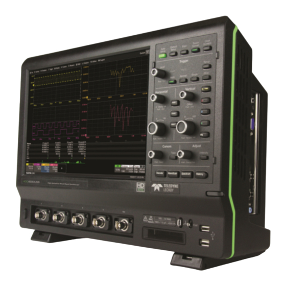
Page 12: The Front Of Your Oscilloscope
SET UP The Front of Your Oscilloscope Touch Screen Display Front Panel Built-in Stylus Holder USB Ports Ground and Calibration Terminals Mixed Signal Interface Channel Inputs Power Button Rotating / Tilting Feet... - Page 13 The touch screen display is the principal viewing and control center Front mounted host USB ports of the oscilloscope. See “Touch Screen Display” for an overview of its can be used for transferring components. data or connecting peripherals such as a mouse or keyboard. The front panel houses buttons and knobs that control different oscilloscope settings.
-
Page 14: The Side Of Your Oscilloscope
SET UP The Side of Your Oscilloscope Video Output VGA, DVI, and HDMI ports for connecting external monitors USB Ports (4) for connecting external USB devices Ethernet Ports (2) for connecting to networks Audio Input/Output Speaker, Mic, and Line-In for connecting external audio devices Feet rotated back Feet rotated front and tilted... -
Page 15: The Back Of Your Oscilloscope
The Back of Your Oscilloscope Built-in Carrying Handle Aux Out connector to send device trigger enabled, trigger out, or pass/ fail output to another device Ref In/Out connector to input an external Reference Clock, or to output a Reference Clock to another instru- ment USBTMC Port for remote control AC Power Inlet for the AC line cord... -
Page 16: Carrying
Go to Utilities > Preference Setup > Remote After start up, configure the connection on the oscilloscope using the to configure remote control. menu options listed below. See the HDO4000 Oscilloscopes Operator’s Manual for more detailed instructions. Other Oscilloscope... -
Page 17: Powering On/Off
If after your trial has ended you decide to purchase an option, you’ll CAUTION. Do not place the instrument so that it is difficult receive another license key from Teledyne LeCroy. Refer to “Software to reach the power cord in case you need to disconnect Options”... -
Page 18: Digital Leadset
To remove the leadset, press in and hold the buttons on each side of the connector, then pull out to release it. Probes HDO4000 Oscilloscopes are compatible with the included passive probes and all Teledyne LeCroy ProBus active probes that are rated for the oscilloscope’s bandwidth. Probe specifications and documentation are available at teledynelecroy.com/HDO4000. - Page 19 USER INTERFACE HDO4000 High Definition Oscilloscopes...
-
Page 20: User Interface
USER INTERFACE Touch Screen Display The entire display is a touch screen. Use your finger or the stylus to touch, double-touch, touch-and-drag, touch-and-hold (right click) or draw a selection box. Many controls that display information also work as “buttons” to access other functions. If you have a mouse installed, you can click anywhere you can touch to activate a control;... - Page 21 A menu bar of drop-down menus lets you access set up dialogs and other A toolbar on the Channel, Math, Memory and Digital dialogs offers functions. All functionality can be accessed through either the menu bar shortcuts to common actions so you don’t have to leave the underlying or other shortcuts.
-
Page 22: Changing The Display
USER INTERFACE Changing the Display NOTE: The available languages are German, Spanish, French, Italian, and Japanese. Other language packs are available from Microsoft’s website. Grid Mode To modify the touch screen grid style, choose Display > Display Setup from Working With Traces the menu bar and make your selections from the Display dialog. - Page 23 Line and Intensity When more data is available than can actually be displayed, Trace Intensity helps The trace style can be set to a series of separate sample Points or a to visualize significant events by applying continuous vector Line. Go to Display > Display Setup. an algorithm that dims less frequently occurring samples.
-
Page 24: Entering/Selecting Data
USER INTERFACE Entering/Selecting Data Touch & Type Touch & Swipe In other cases, Touching once Touch-and-swipe the screen in an up or down direction to scroll long lists of data entry activates a control. values. You can also use scroll bars or Up/Down arrow keys to navigate to fields appear In some cases, you’ll the desired value. - Page 25 Touch & Drag Stylus Use the stylus when you want a more precise selection tool than your finger. Touch-and-drag waveforms, cursors and trigger indicators to reposition them It is especially helpful for selecting exact areas of the grid or values that lie on the grid;...
-
Page 26: Front Panel
Most of the front panel controls duplicate functionality available through the touch screen display. They are covered in more detail in the Basics section and in the HDO4000 Oscilloscopes Operator’s Manual. Below are a few useful front panel controls. Shortcut buttons arranged across the top of the front panel give quick access to commonly used functions. -
Page 27: Basics
BASICS HDO4000 High Definition Oscilloscopes REFERENCE... -
Page 28: Vertical
BASICS Vertical These controls adjust the channel trace along the Y axis. Analog Traces From the Display From the Front Panel Press to turn on/activate analog trace. Touch channel descriptor once to activate the trace and again to Turn to raise or lower Offset (analog) open the Channel setup dialog. - Page 29 Digital Traces From the Display Choose a standard Touch Digital descriptor once to Logic Family, or enter activate the digital trace and custom Threshold again to open the Digital dialog. and Hysteresis. Separate controls allow you to set different values for each bank. Touch tab to choose digital group (1-4).
-
Page 30: Horizontal (Timebase)
BASICS Horizontal (Timebase) These controls adjust the trace along the X axis. From the Front Panel From the Display Turn to raise or lower trigger Delay. Push to return Touch Timebase descriptor to open Delay to zero. the Timebase dialog. Turn to raise or lower Horizontal Scale (Time/div). -
Page 31: Triggers
Touch Trigger descriptor to open Trigger types and modes are described at more length in the the Trigger setup dialog. HDO4000 Oscilloscopes Operator’s Manual. From the Front Panel Press to open the Trigger setup dialog. Press to control acquisition processing: Touch to choose trigger Type. -
Page 32: Zoom
BASICS Zoom Zoom traces display a magnified portion of another trace. From the Display Draw a zoom box on a portion of a From the Front Panel Channel trace. Repeat on another section to open Press the Zoom button. a new zoom trace. Zoom trace opens for every channel trace. -
Page 33: Cursors
Cursors set measurement points on a trace. There are five preset cursor types, each with a unique appearance on the display: Horizontal (Time), Horizontal + Vertical, Vertical (Amplitude), Horizontal (Frequency), and Horizontal (Event). These are described in more detail in the HDO4000 Oscilloscopes Operator’s Manual. From the Front Panel Press to apply cursor. -
Page 34: Measurements & Statistics
BASICS Measurements & Statistics Measurements are waveform parameters that can be expressed as numerical values, such as amplitude or frequency. You can set up-to-eight simultaneous measurements on one or more traces and view the active readout in a table. Statistics can be added to the readout along with histicons, a miniature histogram of the statistical distribution. -
Page 35: Math
Math Math traces display the result of applying a mathematical function (e.g., FFT) to another waveform trace. One important distinction between math functions and measurement parameters is that the result of math is always another waveform, whereas the result of measurement is a number. Choose Math >... -
Page 36: Memories (Reference Waveforms)
BASICS Memories (Reference Waveforms) Memories are traces stored for reference. They can be recalled to the display for comparison with other traces. A memory can be zoomed or measured for better analysis of historical data. You can store up-to-four internal memories (M1-M4). After that, new memories will overwrite previously stored data. -
Page 37: Documenting
Documenting HDO4000 Oscilloscopes offer several ways to preserve and share data—such as print, save to file, email, or save as Notebook Entry— any of which can be associated with the front panel Print button. Go to Utilities > Utilities Setup > Hardcopy to configure how the oscilloscope handles the Print command. -
Page 38: Temperature Dependent Calibration
Temperature Dependent Calibration The HDO4000 is calibrated at the factory prior to being shipped. This calibration is run at 23° C (± 2° C) and is valid for temperatures ± 5° C of the original calibration temperature. Within this temperature range the HDO4000 will meet all of the specifications. When the oscilloscope is used outside of this temperature range a temperature dependent calibration is recommended. -
Page 39: Software Options
The Power Analysis option is used with HDO4K-DPHYbus D MIPI D-PHY/CSI/DSI Decoder Teledyne LeCroy oscilloscopes to make critical power switching device HDO4K-EMB C, SPI, UART and RS-232 Trigger and Decoder measurements, perform control loop modulation analysis, and measure... - Page 40 BASICS...
- Page 41 BASICS REFERENCE HDO4000 High Definition Oscilloscopes...
-
Page 42: Reference
REFERENCE Service Contact your local Teledyne LeCroy service center for calibration or 6. If returning a product to a different country: other service. • Mark the shipment as a Return of US manufactured goods for warranty repair/recalibration. Returning a Product •... -
Page 43: Teledyne Lecroy Service Centers
Teledyne LeCroy Service Centers For a complete list of Teledyne LeCroy offices by country, including our sales and distribution partners, visit: teledynelecroy.com/support/contact World Wide Corporate Office US Protocol Solutions Group Europe Teledyne LeCroy Teledyne LeCroy Teledyne LeCroy SA 700 Chestnut Ridge Road 3385 Scott Boulevard 4, Rue Moïse Marcinhes... -
Page 44: Certifications
EN61000-4-11. equipment for measurement, control, and laboratory use. European Contact:* Electromagnetic Emissions: Teledyne LeCroy Europe GmbH EN 55011:2010, Radiated and Conducted Emissions Group 1, Class A Im Breitspiel 11c D-69126 Heidelberg EN 61000-3-2/A2:2009 Harmonic Current Emissions, Class A... - Page 45 For more • information about proper disposal and recycling of your Teledyne LeCroy Measuring Circuit Terminals: No rated measurement category. product, please visit teledynelecroy.com/recycle. Terminals not intended to be connected directly to the mains supply.
-
Page 46: Warranty
Windows License Agreement The oscilloscope is warranted for normal use and operation, within specifications, for a period of three years from shipment. Teledyne LeCroy The HDO4000 series oscilloscope software runs on the Windows operat- will either repair or, at our option, replace any product returned to one of ing system. - Page 48 926058-00 July, 2015 © 2015 Teledyne LeCroy, Inc. All rights reserved.