Table of Contents
Advertisement
Quick Links
Advertisement
Chapters
Table of Contents
Troubleshooting

Related Manuals for Ricoh SP 330DN


Summary of Contents for Ricoh SP 330DN
- Page 1 M0C3/M0C4/M0C5/ M0C6/M0C7 SERVICE MANUAL...
- Page 2 It is the reader's responsibility when discussing the information contained within this document to maintain a level of confidentiality that is in the best interest of Ricoh USA, Inc. and its member companies. NO PART OF THIS DOCUMENT MAY BE REPRODUCED IN ANY FASHION AND DISTRIBUTED WITHOUT THE PRIOR PERMISSION OF RICOH USA, Inc.
- Page 3 WARNING The Service Manual contains information regarding service techniques, procedures, processes and spare parts of office equipment distributed by Ricoh USA, Inc. Users of this manual should be either service trained or certified by successfully completing a Ricoh Technical Training Program.
- Page 4 LEGEND COMPANY PRODUCT CODE LANIER RICOH SAVIN M0C3 SP 330DN SP 330DN SP 330DN M0C4 SP 330SN SP 330SN SP 330SN M0C5 SP 330SFN SP 330SFN SP 330SFN M0C6 SP 3710DN SP 3710DN SP 3710DN M0C7 SP 3710SF SP 3710SF...
-
Page 5: Table Of Contents
M0C3/M0C4/M0C5/M0C6/M0C7 TABLE OF CONTENTS 1. PRODUCT INFORMATION ............1-1 1.1 MACHINE CODES AND PERIPHERALS CONFIGURATION ........1-1 1.1.1 MAIN FRAME ...................... 1-1 1.1.2 OPTIONS ......................1-1 2. INSTALLATION ................2-1 2.1 INSTALLATION REQUIREMENTS ................2-1 2.1.1 ENVIRONMENT ....................2-1 2.1.2 MAIN MACHINE INSTALLATION ................ 2-1 2.1.3 MOVING AND TRANSPORTING THE MACHINE .......... - Page 6 4.4 SCANNER UNIT (ONLY MF MODELS)............... 4-21 4.4.1 SCANNER UNIT ....................4-21 4.4.2 OPERATION PANEL UNIT ................4-24 Four-line LCD models: ..................4-24 Touch panel models: ..................... 4-25 4.5 ADF/ARDF UNIT (ONLY MF MODELS) ..............4-26 4.5.1 ADF UNIT (FOR FOUR-LINE LCD MODELS) ..........4-26 ADF Unit ........................
- Page 7 4.7.6 BY-PASS FEED ROLLER FRICTION PAD ............4-49 4.7.7 BY-PASS FEED SENSOR ................. 4-50 4.7.8 PAPER FEED CLUTCH ..................4-50 4.7.9 RELAY CLUTCH ....................4-51 4.7.10 REGISTRATION CLUTCH ................4-51 4.7.11 REGISTRATION ROLLER ................4-52 4.7.12 REGISTRATION SENSOR ................4-58 4.8 IMAGE TRANSFER .....................
- Page 8 4.12.10 SPEAKER (ONLY FOR FAX MODELS) ............. 4-85 4.13 IMAGE ADJUSTMENT ..................4-86 4.13.1 REGISTRATION ADJUSTMENT ..............4-86 User Adjustment ....................4-86 Service Adjustment ....................4-86 5. SYSTEM MAINTENANCE ............5-1 5.1 MAINTENANCE MODE (FOR FOUR-LINE LCD MODELS)......... 5-1 5.1.1 OVERVIEW ......................5-1 5.1.2 MENU LIST ......................
- Page 9 @Remote ......................5-45 SP Mode 1 ......................5-46 SP Mode 2 ......................5-48 SP Mode 3 ......................5-50 SP Mode 4 ......................5-52 5.4 FAX SERVICE TEST (ONLY FOR FAX MODELS) ............. 5-53 5.4.1 FAX SERVICE TEST MENU ................5-53 5.4.2 MENU LIST .......................
- Page 10 6.3.1 OVERVIEW ....................... 6-12 6.3.2 ERROR MESSAGES ..................6-12 6.4 FAX ERROR CODES ....................6-20 6.4.1 FAX ERROR CODE STRUCTURE ..............6-20 6.4.2 FAX ERROR CODE TABLE ................6-21 6.5 JAM DETECTION ......................6-24 6.5.1 PAPER JAM....................... 6-24 6.5.2 ORIGINAL JAM (ADF/ARDF) ................6-26 6.6 IMAGE QUALITY ......................
- Page 11 7.3 ADF/ARDF (FOR MF MODELS) ................. 7-15 7.3.1 OVERVIEW ....................... 7-15 ADF........................7-15 ARDF ........................7-16 7.3.2 MECHANISM ..................... 7-17 ADF Paper Path ....................7-17 ARDF Paper Path ....................7-17 7.4 SCANNER (FOR MF MODELS) .................. 7-19 7.4.1 OVERVIEW ....................... 7-19 7.4.2 MECHANISM .....................
- Page 12 7.11.1 OVERVIEW ....................... 7-42 7.11.2 MECHANISM ..................... 7-43 Duplex Printing Process ..................7-43 Printing Order ......................7-44 7.12 ELECTRICAL COMPONENTS ................7-45 7.12.1 OVERVIEW ....................... 7-45 Block Diagram Printer Models ................7-45 Block Diagram MF Models ..................7-46 Board Outline......................7-46 7.13 ENERGY SAVE .....................
- Page 13 IMPORTANT SAFETY NOTICES Warnings, Cautions, Notes In this manual, the following important symbols and notations are used. • A Warning indicates a potentially hazardous situation. Failure to obey a Warning could result in death or serious injury. • A Caution indicates a potentially hazardous situation. Failure to obey a Caution could result in minor or moderate injury or damage to the machine or other property.
- Page 14 Switches and Symbols Where symbols are used on or near switches on machines for Europe and other areas, the meaning of each symbol conforms with IEC60417. Safety Prevention of Physical Injury 1. Before disassembling or assembling parts of the machine and peripherals, make sure that the machine and peripheral power cords are unplugged.
- Page 15 15. Modification or removal of a safety device (fuse, switch, etc.) could lead to a fire and personal injury. Always test the operation of the machine to ensure that it is operating normally and safely after removal and replacement of any safety device. 16.
- Page 16 Observance of Electrical Safety Standards 24. The machine and its peripherals must be installed and maintained by a customer service representative who has completed the training course on those models with exceptions on some machines where the installation can be handled by the user. Safety and Ecological Notes for Disposal •...
- Page 17 • Do not use a vacuum cleaner to remove spilled toner (including used toner). Vacuumed toner may cause a fire or explosion due to sparks or electrical contact inside the cleaner. However, it is possible to use a cleaner designed to be dust explosion-proof. If toner is spilled over the floor, sweep up spilled toner slowly and clean up any remaining toner with a wet cloth.
- Page 18 Laser Safety The Center for Devices and Radiological Health (CDRH) prohibits the repair of laser-based optical units in the field. The optical housing unit can only be repaired in a factory or at a location with the requisite equipment. The laser subsystem is replaceable in the field by a qualified Customer Engineer.
- Page 19 Safety Instructions for the Color Controller Fuse The color controller uses a double pole fuse. If this fuse blows, be sure to replace it with an identical fuse. Batteries Always replace a battery with the same type of battery prescribed for use with the color controller unit.
- Page 20 SYMBOLS AND ABBREVIATIONS This manual uses several symbols and abbreviations. The meaning of those symbols and abbreviations are as follows: Symbol What it means Clip ring Screw Connector Clamp E-ring Flat Flexible Cable Timing Belt Short Edge Feed Long Edge Feed Black Cyan Magenta...
- Page 21 Trademarks Adobe and Acrobat are either registered trademarks or trademarks of Adobe Systems Incorporated in the United States and/or other countries. Android and Google Play are trademarks or registered trademarks of Google Inc. OS X, TrueType, App Store, and Safari are trademarks of Apple Inc., registered in the U.S. and other countries.
- Page 22 Microsoft® Windows Vista® Home Basic Microsoft® Windows Vista® Enterprise • The product names of Windows 7 are as follows: Microsoft® Windows® 7 Starter Microsoft® Windows® 7 Home Premium Microsoft® Windows® 7 Professional Microsoft® Windows® 7 Ultimate Microsoft® Windows® 7 Enterprise •...
- Page 23 • The product names of Windows Server 2012 are as follows: Microsoft® Windows Server® 2012 Foundation Microsoft® Windows Server® 2012 Essentials Microsoft® Windows Server® 2012 Standard Microsoft® Windows Server® 2012 Datacenter • The product names of Windows Server 2012 R2 are as follows: Microsoft®...
-
Page 24: Product Information
PRODUCT INFORMATION R E V I S I O N H I S T O RY P ag e Dat e Ad d ed/ Upd at ed/ New None... -
Page 25: Machine Codes And Peripherals Configuration
Machine Codes and Peripherals Configuration 1. PRODUCT INFORMATION 1.1 MACHINE CODES AND PERIPHERALS CONFIGURATION 1.1.1 MAIN FRAME Printer Models: Name Machine Code Operation Panel Remarks SP 330DN M0C3 Four-line LCD For NA/EU/AA/CHN/TWN SP 3710DN M0C6 Four-line LCD For NA/EU/AA MF Models: Name... -
Page 26: Installation
INSTALLATION R E V I S I O N H I S T O RY P ag e Dat e Ad d ed/ Upd at ed/ New None... -
Page 27: Installation Requirements
Installation Requirements 2. INSTALLATION 2.1 INSTALLATION REQUIREMENTS 2.1.1 ENVIRONMENT 30. Temperature Range: 10°C to 32°C (50°F to 89.6°F) 31. Humidity Range: 15% to 80% RH 32. Ambient Illumination: Less than 2,000 lux (do not expose to direct sunlight) 33. Ventilation: 3 times/hr/person 34. -
Page 28: Moving And Transporting The Machine
Installation Requirements 2.1.3 MOVING AND TRANSPORTING THE MACHINE • It is dangerous to handle the power cord plug with wet hands. Doing so could result in electric shock. • Unplug the power cord from the wall outlet before you move the machine. While moving the machine, take care that the power cord is not damaged under the machine. - Page 29 Installation Requirements • Protect the printer from strong shocks. Impact can damage the hard disk and cause stored files to be lost. As a precautionary measure, files should be copied to another computer. 1. Be sure to check the following: The power switch is turned off.
-
Page 30: Settings For @Remote Service (For Printer Models)
Settings for @Remote Service (for Printer Models) 2.2 SETTINGS FOR @REMOTE SERVICE (FOR PRINTER MODELS) • Prepare the necessary equipment and check the following points before you visit the customer site. For details, ask the @Remote key person. • For information on how to enter the "Maintenance Mode (SP mode)", contact the supervisor in your branch office. - Page 31 Settings for @Remote Service (for Printer Models) 6. Click [Connect Printer] in the SOM menu. 7. Select [Connect Printer] in the printer driver selection screen, input the IP address of the machine and click [OK]. When using a USB cable, select "USB port". M0C3/M0C4/M0C5/M0C6/M0C7...
- Page 32 Settings for @Remote Service (for Printer Models) 8. Click [Printer Configuration] in the [User Tools] tab. 9. Input the access code in the access code input screen and click [OK]. (Administrator's password: Admin) 10. Select the [@Remote] tab in the printer setting screen. 11.
- Page 33 Settings for @Remote Service (for Printer Models) [RC Gate Proxy Server: Proxy Server]: Select [Enable] in the pull down menu. [RC Gate Proxy Server: Proxy Address]: Input the address of the proxy server. [RC Gate Proxy Server: Port Number]: Input the HTTP proxy port number. [RC Gate Proxy Server: User Name]: Enter the HTTP proxy authentication user name.
- Page 34 Settings for @Remote Service (for Printer Models) 6. Execute the registration. SP menu > [@Remote] > [Remote Service] > [Instl:Rgstltn] 7. Check the registration result. SP menu > [@Remote] > [Remote Service] > [Instl:Rgstltn Rst] Value Meaning Solution/ Workaround Succeeded Already registered Check the registration status.
- Page 35 Settings for @Remote Service (for Printer Models) Error Codes When other errors occur, check the following error code list. SP menu > [@Remote] > [Remote Service] > [Instl: ErrorCode] Caused by Operation Error, Incorrect Setting Code Meaning Solution/ Workaround -12003 Attempted registration without execution of a Perform Confirmation before confirmation and no previous registration.
-
Page 36: Settings For @Remote Service (For Mf Models)
Settings for @Remote Service (for MF Models) 2.3 SETTINGS FOR @REMOTE SERVICE (FOR MF MODELS) • Prepare the necessary equipment and check the following points before you visit the customer site. For details, ask the @Remote key person. • For information on how to enter the "Maintenance Mode (SP mode)", contact the supervisor in your branch office. - Page 37 Settings for @Remote Service (for MF Models) Item Settings Touch panel: SP menu > [@Remote] > [Remote Service] > [Proxy Password] 2. Get a Request Number. 3. Enter the "Maintenance Mode (SP mode)". 4. Check if the function flag is "Disable (Default)". Four-line LCD panel: SP menu >...
- Page 38 Settings for @Remote Service (for MF Models) 6. Check the confirmation result. Four-line LCD panel: SP menu > [@Remote] > [Remote Service] > [Instl:Reference] Touch panel: SP menu > [@Remote] > [Remote Service] > [Confirm Result] Value Meaning Solution/ Workaround Succeeded Request number error Check the request number again.
- Page 39 Settings for @Remote Service (for MF Models) After Settings The first manual call after setting is considered as a test call. Be sure to execute the test call, or the first manual call from the customer will be considered as the test call. 1.
- Page 40 Settings for @Remote Service (for MF Models) Code Meaning Solution/ Workaround -2393 External RCG not managed -2394 Mainframe not managed -2395 Box ID for external RCG is illegal. -2396 Mainframe ID for external RCG is illegal. -2397 Incorrect ID2 format Check the ID2 of the machine.
-
Page 41: Preventive Maintenance
PREVENTIVE MAINTENANCE R E V I S I O N H I S T O RY P ag e Dat e Ad d ed/ Upd at ed/ New None... -
Page 42: Preventive Maintenance Tables
Preventive Maintenance Tables 3. PREVENTIVE MAINTENANCE 3.1 PREVENTIVE MAINTENANCE TABLES There are no PM parts in this machine. M0C3/M0C4/M0C5/M0C6/M0C7... -
Page 43: Image Quality Standards
Image Quality Standards 3.2 IMAGE QUALITY STANDARDS Engine Item Specification Remarks Assured Image Area Except Envelopes Except Envelopes Leading edge: 4.2 mm Left/Right: 4.2 mm Trailing edge: 4.2 mm Envelopes Leading edge: 15 mm Left/Right: 10 mm Trailing edge: 10 mm Envelopes Magnification Error ±0.75% or less... - Page 44 Image Quality Standards Copy Item Specification Remarks Resolution 100%/Enlargement: Min 3.6 lines/mm or M: Magnification more Not applicable when using the Reduction: Min 3.6 × M lines /mm or more Assured Image Leading edge: 4.2 mm Envelopes Area Left/Right: 4.2 mm Leading edge: 15 mm Trailing edge: 4.2 mm Left/Right: 10 mm...
-
Page 45: Paper Transfer Quality Standards
Paper Transfer Quality Standards 3.3 PAPER TRANSFER QUALITY STANDARDS Item Specification Remarks Registration Single Side: Scale Width: 0±2.5mm (Main Scan Direction) Vertical: 0±2.0mm (Sub Scan Direction) Duplex: Width: 0±2.5mm (Main Scan Direction) Vertical: 0±2.0mm (Sub Scan Direction) Skew Single Side: Except by-pass tray. -
Page 46: Replacement And Adjustment
REPLACEMENT AND ADJUSTMENT R E V I S I O N H I S T O RY P ag e Dat e Ad d ed/ Upd at ed/ New None... -
Page 47: General Cautions
General Cautions 4. REPLACEMENT AND ADJUSTMENT 4.1 GENERAL CAUTIONS • If there are printer jobs in the machine, print out all jobs in the printer buffer. • Turn off the main power switch and unplug the machine before you do the procedures in this section. -
Page 48: Exterior Covers (Printer Models)
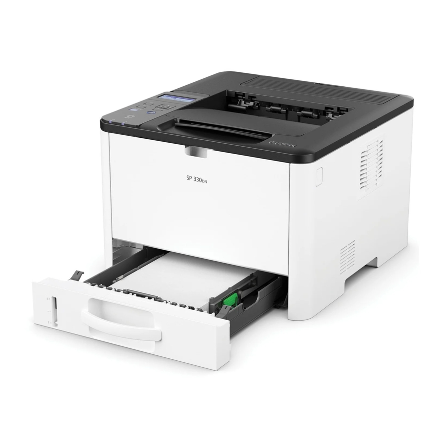
Exterior Covers (Printer Models) 4.2 EXTERIOR COVERS (PRINTER MODELS) 4.2.1 FRONT COVER 1. Pull out the standard paper tray [A]. 2. Open the bypass tray and push in the two tabs [A]. 3. Pull out the bypass tray [A]. M0C3/M0C4/M0C5/M0C6/M0C7... -
Page 49: Left Cover
Exterior Covers (Printer Models) 4. Push the cover release button [B] and open the front cover [A]. 5. Push the right hinge [A] to release it, and then remove the front cover [B]. 4.2.2 LEFT COVER 1. Remove the front cover (Front Cover). - Page 50 Exterior Covers (Printer Models) 3. Pull the front upper part of the left cover [A] to release the hook. • The outside of the cover has marks indicating the position of the hooks. 4. Pull the front bottom part of the left cover [A] to release the hook. 5.
- Page 51 Exterior Covers (Printer Models) 6. Open the left cover [A] about 30 degrees, and then slide it backward to remove it. • There are many hooks and tabs inside the left cover. Before removing the left cover, see the photos below. M0C3/M0C4/M0C5/M0C6/M0C7...
-
Page 52: Rear Cover
Exterior Covers (Printer Models) 4.2.3 REAR COVER 1. Open the rear cover [A]. 2. Slide the shaft [B] in the direction of the blue arrow, and remove the rear cover. 4.2.4 RIGHT COVER 1. Remove the front cover (Front Cover). 2. - Page 53 Exterior Covers (Printer Models) 4. Pull the rear part of the right cover [A] to release the hook. The outside of the cover has marks indicating the position of the hooks. 5. Lift the machine, and release the hook of the right cover [A]. 6.
- Page 54 Exterior Covers (Printer Models) 7. Remove the right cover [A]. • There are many hooks and tabs inside the right cover. Before removing the right cover, see the photos below. M0C3/M0C4/M0C5/M0C6/M0C7...
-
Page 55: Top Cover
Exterior Covers (Printer Models) 4.2.5 TOP COVER 1. Remove the front cover (Front Cover). 2. Remove the left cover (Left Cover). 3. Remove the rear cover (Rear Cover). 4. Remove the right cover (Right Cover). 5. Remove the four screws and a connector, and release the three hooks, and then remove the top cover [A]. -
Page 56: Operation Panel Unit
Exterior Covers (Printer Models) 4.2.6 OPERATION PANEL UNIT 1. Remove the top cover (Top Cover). 2. Turn the top cover over, and release the two hooks to remove the operation panel [A]. M0C3/M0C4/M0C5/M0C6/M0C7 4-10... -
Page 57: Exterior Covers (Mf Models)
Exterior Covers (MF Models) 4.3 EXTERIOR COVERS (MF MODELS) 4.3.1 FRONT COVER 1. Pull out the standard paper tray [A]. 2. Open the bypass tray and push in the two tabs [A]. 3. Pull out the bypass tray [A]. 4-11 M0C3/M0C4/M0C5/M0C6/M0C7... - Page 58 Exterior Covers (MF Models) 4. Push the cover release button [B], and open the front cover [A]. 5. Push the right hinge [A] to release it, and then remove the front cover [B]. M0C3/M0C4/M0C5/M0C6/M0C7 4-12...
-
Page 59: Left Cover
Exterior Covers (MF Models) 4.3.2 LEFT COVER 1. Remove the front cover (Front Cover). 2. Remove the two screws on the front side of the left cover [A]. 3. Pull the front upper part of the left cover [A] to release the hook. •... - Page 60 Exterior Covers (MF Models) 5. Lift the machine, and release the two hooks of the left cover [A]. 6. Open the scanner unit, and pull the upper part of the left cover [A] to release the hook. 7. Open the left cover [A] about 30 degrees, and then slide it backward to remove it. •...
-
Page 61: Rear Cover
Exterior Covers (MF Models) 4.3.3 REAR COVER 1. Open the rear cover [A]. 2. Slide the shaft [B] in the direction of the blue arrow, and remove the rear cover [A]. 4-15 M0C3/M0C4/M0C5/M0C6/M0C7... -
Page 62: Right Cover
Exterior Covers (MF Models) 4.3.4 RIGHT COVER 1. Remove the front cover (Front Cover). 2. Remove the rear cover (Rear Cover). 3. Remove the three screws of the right cover [A]. 4. Pull the rear part of the right cover [A] to release the hook. The outside of the cover has marks indicating the position of the hooks. - Page 63 Exterior Covers (MF Models) 5. Lift the machine, and release the hook of the right cover [A]. 6. Pull the front bottom part of the right cover [A] to release the hook. 7. Remove the right cover [A]. 4-17 M0C3/M0C4/M0C5/M0C6/M0C7...
- Page 64 Exterior Covers (MF Models) • There are many hooks and tabs inside the right cover. Before removing the right cover, see the photos below. M0C3/M0C4/M0C5/M0C6/M0C7 4-18...
-
Page 65: Top Cover
Exterior Covers (MF Models) 4.3.5 TOP COVER 1. Remove the front cover (Front Cover). 2. Remove the left cover (Left Cover). 3. Remove the rear cover (Rear Cover). 4. Remove the right cover (Right Cover). 5. Remove the scanner unit (Scanner Unit). -
Page 66: Models With No Fax
Exterior Covers (MF Models) Models with No Fax: • When re-installing the top cover, always verify that the two paperweights [A] are lifted. If they are not lifted to fit into the paper slot, the paperweights [A] could be damaged. •... -
Page 67: Scanner Unit (Only Mf Models)
Scanner Unit (Only MF Models) 4.4 SCANNER UNIT (ONLY MF MODELS) 4.4.1 SCANNER UNIT 1. Remove the front cover (Front Cover). 2. Remove the left cover (Left Cover). 3. Disconnect the harnesses, FFCs, and ground wires. Four-line LCD models: Touch panel models: Disconnect the scanner FFC by pulling it out straight, because it does not have a lock mechanism. - Page 68 Scanner Unit (Only MF Models) Disconnect the touch panel FFC while pressing the lock release button. Move the harnesses out of the frame so that they do not interfere when lifting the scanner unit. 4. Open the scanner unit [A] and remove the stopper [B]. M0C3/M0C4/M0C5/M0C6/M0C7 4-22...
- Page 69 Scanner Unit (Only MF Models) 5. Remove the spring [A] and the guide plate [B], and then lift the scanner unit while in the wide-open state. 6. Remove the ADF unit [B] (ADF/ARDF Unit (Only MF Models)) and the operation panel unit (Operation Panel Unit) from the scanner unit [A].
-
Page 70: Operation Panel Unit
Scanner Unit (Only MF Models) 4.4.2 OPERATION PANEL UNIT 1. Remove the scanner unit (Scanner Unit). 2. Turn the scanner unit [A] over, and remove the seven screws. 3. Turn the scanner unit over, and release the hooks of the operation panel [A] with a flat head screwdriver. -
Page 71: Touch Panel Models
Scanner Unit (Only MF Models) Touch panel models: Disconnect the FFC while pressing the lock release button. 4-25 M0C3/M0C4/M0C5/M0C6/M0C7... -
Page 72: Adf/Ardf Unit (Only Mf Models)
ADF/ARDF Unit (Only MF Models) 4.5 ADF/ARDF UNIT (ONLY MF MODELS) 4.5.1 ADF UNIT (FOR FOUR-LINE LCD MODELS) ADF Unit 1. Remove the scanner unit (Scanner Unit). 2. Turn the scanner unit over, and move the harnesses out of the frame. 3. -
Page 73: Original Tray
ADF/ARDF Unit (Only MF Models) Original Tray 1. Open the original tray [A] and remove it (two tabs). ADF Pick-Up Roller 1. Open the ADF top cover [A]. 2. Remove the ADF feed unit [B] (tab). 3. Remove the ADF pick-up roller [A]. 4-27 M0C3/M0C4/M0C5/M0C6/M0C7... -
Page 74: Adf Feed Roller
ADF/ARDF Unit (Only MF Models) ADF Feed Roller 1. Remove the ADF feed unit (ADF Pick-Up Roller). 2. Remove the ADF feed roller [A]. ADF Separation Pad 1. Open the ADF top cover. 2. Remove the ADF separation pad [A] (2 hooks, spring x 1). M0C3/M0C4/M0C5/M0C6/M0C7 4-28... -
Page 75: Adf Front Cover
ADF/ARDF Unit (Only MF Models) ADF Front Cover 1. Remove the ADF unit (ADF Unit). 2. Turn the ADF unit over. 3. Remove the ADF front cover [A] ( x 3). • There are many hooks and tabs inside the ADF front cover [A]. Before removing the ADF front cover, see the photos below. -
Page 76: Adf Rear Cover
ADF/ARDF Unit (Only MF Models) ADF Rear Cover 1. Remove the ADF unit (ADF Unit). 2. Turn the ADF unit over. 3. Remove the ADF rear cover [A] ( x 1). • There are many hooks and tabs inside the ADF rear cover [A]. Before removing the ADF rear cover, see the photos below. -
Page 77: Adf Motor
ADF/ARDF Unit (Only MF Models) ADF Motor 1. Remove the ADF unit (ADF Unit). 2. Remove the ADF front cover (ADF Front Cover). 3. Remove the ADF rear cover (ADF Rear Cover). 4. Remove the ADF drive unit [A] while the ADF top cover [B] remains closed ( x 2). -
Page 78: Adf Top Cover
ADF/ARDF Unit (Only MF Models) 6. Remove the ADF motor [A] ( x 2). ADF Top Cover 1. Remove the ADF drive unit (ADF Motor). 2. Open the ADF top cover [A] and remove it (two tabs). Original Set Sensor 1. -
Page 79: Adf Feed Sensor
ADF/ARDF Unit (Only MF Models) 4. Remove the lower guide ( x 3, ground plate, 6 hooks, 2 tabs). 5. Remove the original set sensor [A] ( x 1). ADF Feed Sensor 1. Remove the ADF drive unit (ADF Motor). 2. -
Page 80: Ardf Unit (For Touch Panel Models)
ADF/ARDF Unit (Only MF Models) 4.5.2 ARDF UNIT (FOR TOUCH PANEL MODELS) ARDF Unit 1. Remove the scanner unit (Scanner Unit). 2. Turn the scanner unit over, and move the harnesses out of the frame. 3. Open the ARDF unit [A] and remove it in the direction of the blue arrow (hooks). Original Tray 1. -
Page 81: Ardf Pick-Up Roller, Ardf Feed Roller
ADF/ARDF Unit (Only MF Models) ARDF Pick-Up Roller, ARDF Feed Roller 1. Open the ARDF top cover [A]. 2. Remove the ARDF feed unit [B] (tab). 3. Remove the ARDF pick-up roller [A]. 4. Remove the ARDF feed roller [B]. 4-35 M0C3/M0C4/M0C5/M0C6/M0C7... -
Page 82: Ardf Separation Pad
ADF/ARDF Unit (Only MF Models) ARDF Separation Pad 1. Open the ARDF top cover. 2. Remove the ARDF separation pad [A] (2 hooks, spring x 1). ARDF Front Cover 1. Remove the ARDF unit (ARDF Unit). 2. Turn the ARDF unit over. 3. -
Page 83: Ardf Rear Cover
ADF/ARDF Unit (Only MF Models) • There are many hooks and tabs inside the ARDF front cover. Before removing the ARDF front cover, see the photos below. ARDF Rear Cover 1. Remove the ARDF unit (ARDF Unit). 2. Turn the ARDF unit over. 3. -
Page 84: Ardf Motor
ADF/ARDF Unit (Only MF Models) • There are many hooks and tabs inside the ARDF rear cover. Before removing the ARDF rear cover, see the photos below. ARDF Motor 1. Remove the ARDF unit (ARDF Unit). 2. Remove the ARDF front cover (ARDF Front Cover). - Page 85 ADF/ARDF Unit (Only MF Models) 5. Remove the ARDF drive unit [A]. When removing/attaching the ARDF drive unit, make sure to route the harnesses carefully so that they will not be damaged. 6. Remove the ARDF motor assembly [A]. 4-39 M0C3/M0C4/M0C5/M0C6/M0C7...
-
Page 86: Ardf Top Cover
ADF/ARDF Unit (Only MF Models) 7. Remove the ARDF motor [A]. ARDF Top Cover 1. Remove the ARDF drive unit (ARDF Motor). 2. Open the ARDF top cover [A] and remove it (two tabs). M0C3/M0C4/M0C5/M0C6/M0C7 4-40... -
Page 87: Original Set Sensor
ADF/ARDF Unit (Only MF Models) Original Set Sensor 1. Remove the ARDF drive unit (ARDF Motor). 2. Turn the ARDF drive unit over. 3. Remove the sensor cover [A]. 4. Remove the original set sensor [A]. 4-41 M0C3/M0C4/M0C5/M0C6/M0C7... -
Page 88: Ardf Feed Sensor
ADF/ARDF Unit (Only MF Models) ARDF Feed Sensor 1. Remove the ARDF drive unit (ARDF Motor). 2. Turn the ARDF drive unit over. 3. Remove the pressure plate [A] (4 hooks). 4. Remove the lower guide [A] (6 hooks). 5. Remove the ARDF feed sensor [A]. M0C3/M0C4/M0C5/M0C6/M0C7 4-42... -
Page 89: Laser Unit
Laser Unit 4.6 LASER UNIT • Turn off the main power switch and unplug the machine before attempting any of the procedures in this section. Laser beams can seriously damage your eyes. 4.6.1 CAUTION DECAL LOCATIONS A caution decal is attached as shown below. •... -
Page 90: Laser Unit Thermistor
Laser Unit 4.6.3 LASER UNIT THERMISTOR 1. Remove the top cover (Printer models: Cover, MF models: Cover). 2. Release the four hooks, and remove the laser unit top cover [A]. 3. Remove the laser unit thermistor [A]. M0C3/M0C4/M0C5/M0C6/M0C7 4-44... -
Page 91: Paper Feed
Paper Feed 4.7 PAPER FEED 4.7.1 PAPER FEED ROLLER 1. Pull out the standard paper tray. 2. Remove the AIO. 3. Set the machine with the rear side facing down, resting on the table. 4. Remove the two clips, and slide the paper feed shaft [A] to the left side. 5. -
Page 92: Friction Pad
Paper Feed 4.7.2 FRICTION PAD 1. Remove the paper tray unit from the machine before removing the friction pad. 2. Remove the friction pad [A] (2 hooks, spring x 1). From the bottom side of the paper tray, release the hooks with a flat head screwdriver. The spring is a different service part from the friction pad. -
Page 93: By-Pass Feed Solenoid
Paper Feed 4.7.4 BY-PASS FEED SOLENOID 1. Remove the left cover (Printer models: Left Cover, MF models: Left Cover). 2. Remove the solenoid cover [A]. 3. Remove the by-pass feed solenoid [A]. 4.7.5 BY-PASS FEED ROLLER 1. Remove the left cover (Printer models: Left Cover, MF models: Left... - Page 94 Paper Feed • When re-installing the by-pass lower guide plate [A], align the lower pins with the hole in the frame, and then attach the upper hooks. • Be careful that the springs [B] and the ground plate [C] do not fall inside the machine during re-installation.
-
Page 95: By-Pass Feed Roller Friction Pad
Paper Feed 6. Remove the gear [C] (hook). 7. Slide the by-pass feed roller shaft [A] to the left side, and remove it. 8. Remove the metal cover [B] from the by-pass feed roller [C]. 4.7.6 BY-PASS FEED ROLLER FRICTION PAD 1. -
Page 96: By-Pass Feed Sensor
Paper Feed 4.7.7 BY-PASS FEED SENSOR 1. Remove the right cover (Printer models: Right Cover, MF models: Right Cover). 2. Remove the by-pass feed sensor [A]. 4.7.8 PAPER FEED CLUTCH 1. Remove the drive unit (Drive Unit). 2. Remove the paper feed clutch [A]. Fit the stopper of the paper feed clutch over the tab on the machine. -
Page 97: Relay Clutch
Paper Feed 4.7.9 RELAY CLUTCH 1. Remove the drive unit (Drive Unit). 2. Remove the relay clutch [A]. 4.7.10 REGISTRATION CLUTCH 1. Remove the drive unit (Drive Unit). 2. Remove the registration clutch [A]. 4-51 M0C3/M0C4/M0C5/M0C6/M0C7... -
Page 98: Registration Roller
Paper Feed 4.7.11 REGISTRATION ROLLER 1. Remove the AIO. 2. Only for MF models, remove the scanner unit (Scanner Unit). 3. Remove the top cover (Printer models: Cover, MF models: Cover). 4. Remove the fusing unit (Fusing Unit). 5. Remove the PSU (PSU). 6. - Page 99 Paper Feed 13. Slightly flex the side frames outward, and remove the exit roller base [A] and grounding plate [B]. When re-installing the exit roller base, remove the gear [C] temporarily so that it does not get damaged. 14. Pass the harnesses through the hole inside the machine. 15.
- Page 100 Paper Feed 16. Remove the main power cord [A] on the right side. 17. Remove the rear lower cover [A]. There is a screw behind the tray cover [B]. 18. Remove the bushings on both sides, and remove the duplex cover [A]. M0C3/M0C4/M0C5/M0C6/M0C7 4-54...
- Page 101 Paper Feed 19. Set the machine with the front side facing down, resting on the table. 20. Release the link [A]. 21. Remove the bracket [A] on the left side. 22. Remove the bushings on both sides and pass the harness [B] through the hole inside the machine, and then remove the duplex transport guide [A].
- Page 102 Paper Feed 24. Pass the harness [B] through the hole inside the machine, and remove the registration unit [A]. M0C3/M0C4/M0C5/M0C6/M0C7 4-56...
- Page 103 Paper Feed 25. Remove the upper guide plate [A] (2 hooks). 26. Remove the registration roller (follower) [A] as shown below (spring x 2, plastic parts x 2). 4-57 M0C3/M0C4/M0C5/M0C6/M0C7...
-
Page 104: Registration Sensor
Paper Feed 27. Remove the registration roller (drive) [A] ( x 2, bushing x 2). 4.7.12 REGISTRATION SENSOR 1. Remove the registration unit (Registration Roller). 2. Turn the registration unit over. 3. Remove the registration sensor [A] ( x 1, 3 hooks). M0C3/M0C4/M0C5/M0C6/M0C7 4-58... -
Page 105: Image Transfer
Image Transfer 4.8 IMAGE TRANSFER 4.8.1 TRANSFER ROLLER 1. Remove the front cover (Printer models: Front Cover, MF models: Front Cover). 2. Remove the AIO. 3. Remove the transfer roller [A] as shown below. 4. Remove the bushing x 2 [C], spring x 2 [D], gear x 1 [B], collar x 1 [A] from the transfer roller. •... -
Page 106: Toner End Sensor
Image Transfer 4.8.2 TONER END SENSOR 1. Remove the left cover (Printer models: Left Cover MF models: Left Cover). 2. Remove the drive unit (Drive Unit). 3. Remove the toner end sensor [A]. M0C3/M0C4/M0C5/M0C6/M0C7 4-60... -
Page 107: Quenching Lamp
Image Transfer 4.8.3 QUENCHING LAMP 1. Remove the top cover (Printer models: Top Cover MF models: Cover). 2. Remove the AIO. 3. Remove the quenching lamp with the case [A] (2 hooks). 4. Remove the quenching lamp [A] from the case (hook x 3). 4-61 M0C3/M0C4/M0C5/M0C6/M0C7... -
Page 108: Fusing And Exit
Fusing and Exit 4.9 FUSING AND EXIT • Switch off the main power, unplug the machine from its power source, and allow the fusing unit to cool before removing it. 4.9.1 FUSING UNIT The non-contact thermistor is installed so that there is a gap of 1 mm between it and the surface of the hot roller. - Page 109 Fusing and Exit 3. Disconnect the connectors from the fusing unit [A]. 4. Pass the harnesses through the hole [A] inside the machine. 5. Remove the fusing unit [A] ( x 4). 4-63 M0C3/M0C4/M0C5/M0C6/M0C7...
-
Page 110: Fusing Upper Cover
Fusing and Exit • Make sure that the two bushings [A] on both sides remain in position. 4.9.2 FUSING UPPER COVER 1. Remove the fusing unit (Fusing Unit). 2. Remove the fusing upper cover [A]. M0C3/M0C4/M0C5/M0C6/M0C7 4-64... -
Page 111: Thermostat
Fusing and Exit 4.9.3 THERMOSTAT 1. Remove the fusing unit (Fusing Unit). 2. Remove the fusing upper cover (Fusing Upper Cover) 3. Remove the thermostat [A]. 4-65 M0C3/M0C4/M0C5/M0C6/M0C7... -
Page 112: Fusing Thermistor
Fusing and Exit 4.9.4 FUSING THERMISTOR 1. Remove the fusing unit (Fusing Unit). 2. Remove the fusing upper cover (Fusing Upper Cover). 3. Remove the fusing front cover [A]. 4. Remove the fusing thermistor [A]. M0C3/M0C4/M0C5/M0C6/M0C7 4-66... -
Page 113: Fusing Lamp
Fusing and Exit 4.9.5 FUSING LAMP 1. Remove the fusing unit (Fusing Unit). 2. Remove the fusing side covers [A] ( x 2 each). 3. Turn the fusing unit over. 4. Remove the screws on both sides ( x 1 each). Hold the terminal and flat nut with your finger firmly. - Page 114 Fusing and Exit 5. Remove the fusing lamp [A]. Pull out the fusing lamp while aligning the flat terminal [B] with the notch [A] on the right side of the hot roller. When installing a new lamp, the flat terminal [A] as shown below must be on the right side of the fusing unit (fusing cable side).
-
Page 115: Hot Roller Stripper Pawls
Fusing and Exit 4.9.6 HOT ROLLER STRIPPER PAWLS 1. Remove the fusing unit (Fusing Unit). 2. Remove the fusing upper cover (Fusing Upper Cover). 3. Remove the metal holders [A] (1 holder for each pawl: x 2 each). 4. Remove the hot roller stripper pawls [A] (1 spring for each pawl). 4.9.7 PAPER EXIT SENSOR 1. -
Page 116: Duplex
Duplex 4.10 DUPLEX 4.10.1 DUPLEX SENSOR 1. Open the rear cover. 2. Remove the duplex sensor [A]. M0C3/M0C4/M0C5/M0C6/M0C7 4-70... -
Page 117: Drive
Drive 4.11 DRIVE 4.11.1 MAIN MOTOR 1. Remove the left cover (Printer models: Left Cover, MF models: Left Cover). 2. Remove the main board (Main Board). 3. For MF models, remove the main board bracket (FCU (Only for Fax Models)). 4. -
Page 118: Drive Unit
Drive Make sure that the stoppers of the clutches are set over the projections on the harness guide plate. 4.11.2 DRIVE UNIT 1. Remove the left cover (Printer models: Left Cover MF models: Left Cover). 2. Remove the main board (Main Board (Printer Models)). - Page 119 Drive 5. Release the four hooks, and remove the timing belt cover [A]. 6. Remove the gear [B] and loosen the timing belt [C]. 7. Remove the drive unit [A]. Printer models: MF models: When re-installing the harness guide plate, first set the stopper of the relay clutch [A] over the projection.
- Page 120 Drive Make sure that the stoppers of the clutches are set over projections on the harness guide plate. M0C3/M0C4/M0C5/M0C6/M0C7 4-74...
-
Page 121: Duplex Motor
Drive 4.11.3 DUPLEX MOTOR 1. Remove the top cover (Printer models: Top Cover MF models: Cover). 2. Remove the duplex motor [A]. 4-75 M0C3/M0C4/M0C5/M0C6/M0C7... -
Page 122: Electrical Components
Electrical Components 4.12 ELECTRICAL COMPONENTS 4.12.1 MAIN BOARD Settings such as network settings and initial settings are registered in the flash memory on the main board. When replacing the main board, ask the customer to back up/restore the settings in Administrator Tools in the WIM. -
Page 123: Main Board (Mf Four-Line Lcd Models)
Electrical Components Main Board (MF Four-line LCD Models) 1. Remove the left cover (Left Cover). 2. Remove the main board [A]. Disconnect the scanner FFC by pulling it out straight, because it does not have a lock mechanism. 4-77 M0C3/M0C4/M0C5/M0C6/M0C7... -
Page 124: Main Board (Mf Touch Panel Models)
Electrical Components Main Board (MF Touch Panel Models) 1. Remove the left cover (Left Cover). 2. Remove the main board [A]. Disconnect the scanner FFC by pulling it out straight, because it does not have a lock mechanism. Disconnect the touch panel FFC while pressing the lock release button. When installing the main board [A], be careful of the connection to the FCU behind it. -
Page 125: When Installing The New Main Board
Electrical Components When Installing the New Main Board After replacing the main board, the following settings must be made correctly. 1. Enter the "Maintenance Mode", and set the SPs below; • Destination Four-line LCD models: SP menu > [Engine Maintenance] > [Destination] Touch panel models: SP menu >... -
Page 126: Psu
Electrical Components 4.12.2 PSU Do not touch the areas outlined in red in the following diagrams when replacing the PSU. Residual charge on the board may cause electric shock. 1. Remove the right cover (Printer models: Right Cover, MF models: Right Cover). -
Page 127: Hvp
Electrical Components 4.12.3 HVP 1. Remove the right cover (Printer models: Right Cover, MF models: Right Cover). 2. Remove the HVP [A]. After removing the HVP, the terminal pins are left in the machine, so be careful not to lose them. -
Page 128: Cooling Fan
Electrical Components 4.12.4 COOLING FAN 1. Remove the right cover (Printer models: Right Cover, MF models: Right Cover). 2. Remove the cooling fan [A]. • Install the cooling fan with its decal facing the outside of the machine. 4.12.5 ENVIRONMENT THERMISTOR 1. -
Page 129: Id Chip Board
Electrical Components 4.12.6 ID CHIP BOARD 1. Remove the top cover (Printer models: Cover, MF models: Cover). 2. Release the three hooks, and remove the ID chip board [A]. 4.12.7 FRONT COVER SWITCH, REAR COVER SWITCH 1. Remove the left cover (Printer models: Left Cover, MF models: Left... -
Page 130: Usb Port (Only For Mf Models)
Electrical Components 4.12.8 USB PORT (ONLY FOR MF MODELS) 1. Remove the left cover (Left Cover). 2. Remove the USB port [A]. 4.12.9 FCU (ONLY FOR FAX MODELS) 1. Remove the main board (Main Board (MF Touch Panel Models)). 2. Remove the main board bracket [A]. 3. -
Page 131: Speaker (Only For Fax Models)
Electrical Components 4.12.10 SPEAKER (ONLY FOR FAX MODELS) 1. Remove the left cover (Left Cover). 2. Remove the speaker [A]. 4-85 M0C3/M0C4/M0C5/M0C6/M0C7... -
Page 132: Image Adjustment
Image Adjustment 4.13 IMAGE ADJUSTMENT 4.13.1 REGISTRATION ADJUSTMENT User Adjustment The paper registration can also be adjusted with the user mode ("User Tools "). For details, see the "User Guide". Service Adjustment 1. Enter the "Maintenance Mode (SP mode)". For information on how to enter the "Maintenance Mode (SP mode)", contact the supervisor in your branch office. - Page 133 Image Adjustment • Adjust the margins of the test page so that they are equal in size. • (1): Feed Direction • (2): Vertical Adjustment • (3): Horizontal Adjustment • (4): Print Area 4-87 M0C3/M0C4/M0C5/M0C6/M0C7...
-
Page 134: System Maintenance
SYSTEM MAINTENANCE R E V I S I O N H I S T O RY Pa g e Da t e Ad d e d / Upd a t ed / Ne w 10/17/2018 Added DFU Message to EM Life Display 10/17/2018 Added DFU Message to EM Life Display 10/17/2018... -
Page 135: Maintenance Mode (For Four-Line Lcd Models)
Maintenance Mode (for Four-line LCD Models) 5. SYSTEM MAINTENANCE 5.1 MAINTENANCE MODE (FOR FOUR-LINE LCD MODELS) 5.1.1 OVERVIEW This model has several service menus. Each service menu has several adjustment items. Maintenance Mode Menu • Display Info • Engine Maintenance •... -
Page 136: Menu List
Maintenance Mode (for Four-line LCD Models) 5.1.2 MENU LIST Display Info Menu Description Model Name Displays the model name, depends on engine firmware settings CTL FW Version Displays the firmware version Version FAX FW Version Displays the fax firmware version. (Only for fax models) Engine FW Version Displays the engine firmware version... - Page 137 Maintenance Mode (for Four-line LCD Models) Menu Description Interval Setting Corrects the face curl of paper. 0: OFF (32ppm) 1: Sets the engine speed to half after printing 1 minute. 2: Sets the engine speed at 13ppm. [0 to 2 / 0 / 1 /step] Toner Near Sheets Adjusts the printable sheets between "toner near end"...
- Page 138 Maintenance Mode (for Four-line LCD Models) Menu Description [120 to 175 / 155 / 1°C/step] Thick2 Paper Adjusts the fusing temperature for thick 2 paper. [170 to 200 / 185 / 1°C/step] Thick1 Paper Adjusts the fusing temperature for thick 1 paper. [175 to 200 / 185 / 1°C/step] Paper Buckle Vert .Bp Plain...
- Page 139 Maintenance Mode (for Four-line LCD Models) Rev. 10/17/2018 Menu Description Motor Dup Motor Output check (Duplex motor normal) Normal Dup Motor Output check (Duplex motor reverse) Revers ⇒ EM Life Display Sets whether to display an alert when each EM parts yield of this DFU (Designed for Factory machine is reached.
- Page 140 Maintenance Mode (for Four-line LCD Models) Menu Description Time OPC Alert Displays the OPC life information (Alert status) Status Displays the OPC life information (Pre-Alert status) Pre-Alert Status Prt Cartridge Kind ID Displays the toner cartridge (AIO) information (Kind ID). Info Toner End Displays the toner cartridge (AIO) information (Toner End...
- Page 141 Maintenance Mode (for Four-line LCD Models) Menu Description Horiz Bypass [-40.0 to 40.0 / -7.0 (Default) / 0.1 mm/step] tray Vert Bypass [-40.0 to 40.0 / 23.0 (Default) / 0.1 mm/step] Plain Vert Bypass [-40.0 to 40.0 / 23.0 (Default) / 0.1 mm/step] Thick Vert Bypass [-40.0 to 40.0 / 23.0 (Default) / 0.1 mm/step]...
-
Page 142: Scan Maintenance (Only For Mf Models)
Maintenance Mode (for Four-line LCD Models) Menu Description 5%-7% Displays the number of pages printed with coverage 5 to 7%. 8%-9% Displays the number of pages printed with coverage 8 to 9%. 10%-19% Displays the number of pages printed with coverage 10 to 19%. 20%-29% Displays the number of pages printed with coverage 20 to 29%. -
Page 143: Factory Default
Maintenance Mode (for Four-line LCD Models) Menu Description [-0.9 to 0.9 / 0 (Default)/ 0.1 %/step] Flatbed Main Reg. Adjusts the Flatbed Scan main-scan magnification. [-0.9 to 0.9 / 0 (Default)/ 0.1 %/step] Flatbed Sub Reg. Adjusts the Flatbed Scan sub-scan magnification. [-0.9 to 0.9 / 0 (Default)/ 0.1 %/step] Factory Default Menu... -
Page 144: System Maintenance
Maintenance Mode (for Four-line LCD Models) System Maintenance Menu Description Air Print Enable Sets whether the Air Print function is enabled or disabled [Disable/ Enable (Default)] Debug Tools [Off (Default)/ NIC/ USB] @Remote Menu Description Toner Supply Alarm Supply Alarm Sets the toner supply alarm. - Page 145 Maintenance Mode (for Four-line LCD Models) Menu Description [0 to 4294967295 / 60 / 1 sec/step] HTTP Con Timeout Specifies the connect timeout interval when calling the RCG. [1 to 90 / 30 / 1 sec/step] HTTP Sen Timeout Specifies the send timeout interval when calling the RCG. [0 to 100 / 30 / 1 sec/step] HTTP Rec Timeout Specifies the receive timeout interval when calling the...
- Page 146 Maintenance Mode (for Four-line LCD Models) Menu Description Update Result Displays the center information update results. Mgn Expir Time Specifies the margin to notify the proximity of the expiration of the certification. [2592000 to 15552000 / 2592000 / 1 sec/step] NotiTime ExpTime Displays the date and time to notify the proximity of the expiration of the certification.
- Page 147 Maintenance Mode (for Four-line LCD Models) Menu Description Instl:Ref Section Displays the section name. Instl:Rgstltn Executes registration. Instl:Rgstltn Rst Displays the registration result. Instl:ErrorCode Displays the error code. Instl Clear Clears the @Remote installation. Common KeyInfo Performs initialization of common key information. Init Remote Diagnostics Executes repair request notification.
-
Page 148: Maintenance Mode (For Touch Panel Models)
Maintenance Mode (for Touch Panel Models) 5.2 MAINTENANCE MODE (FOR TOUCH PANEL MODELS) 5.2.1 OVERVIEW This model has several service menus. Each service menu has several adjustment items. Maintenance Mode Menu • Information Display • Engine Service Setting • Scanner Service Setting •... -
Page 149: Engine Service Setting
Maintenance Mode (for Touch Panel Models) Menu Description Jam Counter Jam Total Displays the number of paper jams at each location. Printer Out Bin Internal Tray1 Tray2 Duplex WiFi Channel Type Displays the WiFi channel type. Engine Service Setting Menu Description PnP Name DFU (Designed for Factory Use). - Page 150 Maintenance Mode (for Touch Panel Models) Menu Description [-40.0 to 40.0 / 17.0 (Default) / 0.1 mm/step] Vert. Tray2 Thick Vert. Tray2 [-40.0 to 40.0 / 17.0 (Default) / 0.1 mm/step] Thin Horiz. [-40.0 to 40.0 / -5.0 (Default) / 0.1 mm/step] Bypass [-40.0 to 40.0 / 17.0 (Default) / 0.1 mm/step] Vert.
- Page 151 Maintenance Mode (for Touch Panel Models) Menu Description "toner end". [50 to 150 / 100 / 25 dot/step] Trans. Roller Bias Adjusts the transfer roller bias. [-6 to 6 / 0 / 1/step] Developer Bias Adjusts the developer bias. [270 to 330 / 250 / 15/step] Charge Bias [1100 to 1300 / 1200 / 25/step] Fusing Unit...
- Page 152 Maintenance Mode (for Touch Panel Models) Menu Description Paper Vert .Tray1 [-8 to 8 / -2 (Default) / 1mm/step] Plain Paper Vert .Tray1 [-8 to 8 / 0 (Default) / 1mm/step] Thick Paper Vert .Tray1 [-8 to 8 / -2 (Default) / 1mm/step] Thin Paper Vert .Tray2 [-8 to 8 / -2 (Default) / 1mm/step]...
- Page 153 Maintenance Mode (for Touch Panel Models) Rev. 10/17/2018 Menu Description ⇒ DFU (Designed for Factory machine is reached. Use) [On or Off (Default)] SC559 Detection [On or Off (Default)] Clear Engine Memory Resets the engine settings stored in the EEPROM to factory default.
- Page 154 Maintenance Mode (for Touch Panel Models) Menu Description [On or Off (Default)] With the main motor rotation count feature, the machine can be set to stop printing after the print total exceeds a certain set value. If the print count exceeds this value, then "Replace Print Cartridge"...
-
Page 155: Scanner Service Setting
Maintenance Mode (for Touch Panel Models) Menu Description Displays the machine series number. Serial No Displays the machine serial No. Inrush Control Sets the Inrush Control mode. When using with an external power supply instead of a commercial power supply, set to "On". [Off (Default)/ On] Flicker Control Sets the Flicker Control mode. -
Page 156: Fax Service Setting
Maintenance Mode (for Touch Panel Models) Fax Service Setting Menu Description Modem RX Level Sets the reception level. Settings [-43 dBm (Default)/ -33 dBm/ -26 dBm/ -16 dBm] TX Level Sets the transmission level. [-15 to -1 / -9(Default)/ 1dBm/ step] Cable Equalizer These selectors are used to improve the pass-band characteristics of analogue signals on the telephone line. - Page 157 Maintenance Mode (for Touch Panel Models) Menu Description [No Monitoring/ Up To Phase B (Default)/ All TX Phases] Stop/Clear Key Pressing the Stop/Clear key can stop the current receiving operation. Received data is lost. [No Functional (Default)/ Functional] Off-Hook Sets the Off-Hook detection period. Detection [200 msec (Default)/ 800 msec] [0~9 / 2 (Default/ 1digit/step]...
- Page 158 Maintenance Mode (for Touch Panel Models) Menu Description Settings Transmission T [100 ms (Default)] Minimum Pause Sets the minimum pause during tone dialing In Tone Dial [100 ms (Default)/ 150 ms/ 200 ms] Attenuator of Sets the attenuator for pseudo ringback tone to the line Pseudo Ring [0 to 15 / 10 (Default)/ 1 dB/step] DTMF Level...
- Page 159 Maintenance Mode (for Touch Panel Models) Menu Description Settings and then transmits an RTN depending on the decoding error rate that is set by this setting (Number of lines containing an error per page / Total number of lines per page). [10% (Default)/ 15%] V34 Modem [Permitted (Default)/ Prohibited]...
-
Page 160: Print Reports
Maintenance Mode (for Touch Panel Models) Print Reports Menu Description G3 Protocol dump list G3 protocol dump of the latest communication is printed. Off (Default)/ Error/ On CTL SP Menu Description Air Print Sets whether the Air Print function is enabled or disabled. Enable [Disable/ Enable (Default)] Debug... -
Page 161: Remote
Maintenance Mode (for Touch Panel Models) Menu Description Clears/ resets the contents of the controller memory (all data programmed by the user, log data application counters) to factory default. After executing, initial setup menu starts after power-on. @Remote Menu Description Toner Supply Alarm Supply Alarm Sets the toner supply alarm. - Page 162 Maintenance Mode (for Touch Panel Models) Menu Description [0 to 4294967295 / 60 / 1 sec/step] Connection Timeout Specifies the connect timeout interval when calling the RCG. [1 to 90 / 30 / 1 sec/step] Send Timeout Specifies the send timeout interval when calling the RCG. [0 to 100 / 30 / 1 sec/step] Receive Timeout Specifies the receive timeout interval when calling the...
- Page 163 Maintenance Mode (for Touch Panel Models) Menu Description Center Polling Displays the center control polling date and time. Test Flag Sets the test flag. [0 to 255 / 0 / 1/step] Update Result Displays the center information update results. Valid Adv.Notice Specifies the margin to notify the proximity of the expiration of the certification.
- Page 164 Maintenance Mode (for Touch Panel Models) Menu Description Letter Number Inputs the request number. Confirm Execute Executes the reference. Confirm Result Displays the reference result. Confirm Place Displays the section name. Register Execute Executes registration. Register Result Displays the registration result. Error Code Displays the error code.
-
Page 165: Smart Organizing Monitor (Som)
Smart Organizing Monitor (SOM) 5.3 SMART ORGANIZING MONITOR (SOM) 5.3.1 OVERVIEW This machine has an operation panel, so the machine status can be checked and setup can be performed from the operation panel. However, as in the previous product, the SOM (Smart Organizing Monitor) utility can be executed from a PC. -
Page 166: Menu List
Smart Organizing Monitor (SOM) 4. Input the access code in the [Access Code] entry dialog, and click [OK]. Each mode has a different access code. • Guest mode: (none) • Administrator mode: Admin • Service engineer mode: Contact the supervisor in your branch office. 5.3.2 MENU LIST The displayed menu depends on the login mode Menu... -
Page 167: Paper Input
Smart Organizing Monitor (SOM) Menu Description Guest Admin Service mode mode mode Network 1 Adjusts network settings (Information, Interface, TCP/IP). Network 2 Adjusts network settings (IPX, SMTP). Network 3 Adjusts network settings (SNMP, Apple Talk). Wireless Adjusts network settings (Wireless). Printer Adjusts the printer driver settings (PCL, PS). - Page 168 Smart Organizing Monitor (SOM) Item Selections Remarks Paper/ Cardstock/ Color Paper model. Tray 2 Paper A4 */ Letter * Size Tray 2 Paper Plain Paper */ Recycled Paper/ Thick Paper 1/ Type Thick Paper 2 / Thin Paper/ Letterhead/ Preprinted Paper/ Prepunched Paper/ Color Paper Bypass Tray A4 */ Letter */ B5/ B6/ A5/ A6/ Legal/ 8.5"...
-
Page 169: Maintenance
Smart Organizing Monitor (SOM) Item Selections Remarks Custom one digit after the decimal Paper Size: point in mm. Vertical If an input value is more than the maximum value, then it will be treated as the maximum value. If an input value is less than the minimum value, then it will be treated as the minimum value. -
Page 170: System
Smart Organizing Monitor (SOM) Group Item Selections Remarks Horizontal * step to +5.1 mm. (-15 to +15) 0.24 mm per step. Range is -3.6 mm Adjustment step to +3.6 mm Vertical * Registration Tray 2 Print Test Sheet Sends a PCL command to the printer to print a test sheet. - Page 171 Smart Organizing Monitor (SOM) Item Selections Remarks Auto Continue On/ Off * Copies 1*-999 Sub Paper Off */ Auto Size 2 Sided Print Off */ Short Edge Bind/ Long Edge Bind Blank Page Print */ Not Print "Manual Duplex/Cover" Print has higher priority than the "Blank Pages"...
-
Page 172: Ipv6
Smart Organizing Monitor (SOM) Item Selections Remarks not use". English */ French/ German/ Italian/ Spanish/ The factory setting is Language Dutch/ Danish/ Swedish/ Norwegian/ Portuguese/ English if the market is NA, Polish/ Czech/ Hungarian/ Finnish/ Japanese/ EU or ASIA. Simpl.Chinese/ Trad.Chinese Russian/ Turkish/ Brazilian/Arabic/ Kazakh Options When Stop Printing *... -
Page 173: Network 1
Smart Organizing Monitor (SOM) *: Default Network 1 Group Item Selections Remarks Information Device String length is 32 Name Comment String length is 32 Mac Address Active Interface Wi-Fi Direct Address TCP/IP IP Address xxx.xxx.xxx.xxx This setting is not available if DHCP is enabled. - Page 174 Smart Organizing Monitor (SOM) Group Item Selections Remarks xxx.xxx.xxx.xxx Default This setting is not available if DHCP is Gateway enabled. Address If this setting is changed, the printer power must be turned off/on for the new setting to take effect. Will show all zero if network initialization is not finished.
-
Page 175: Network 2
Smart Organizing Monitor (SOM) Group Item Selections Remarks 15 / 60 */ 300 I/O Timeout (Network) Ethernet Auto Select */ 10M half/ Speed 10M full/ 100M half/ 100M full Wi-Fi Type 2.4 GHZ * On/ Off * Fixed USB Port Active /Inactive * Wireless Function... -
Page 176: Network 3
Smart Organizing Monitor (SOM) Group Item Selections Remarks The factory default is 25. User Name Null string* Up to 32 alphanumeric characters. The factory default is 'null string'. Password Null string* Up to 32 alphanumeric characters. The factory default is 'null string'. User-input characters and characters read back from the printer will show "*"... -
Page 177: Wireless
Smart Organizing Monitor (SOM) Group Item Selections Remarks Service Required E-mail Address Up to 64 alphanumeric characters. Print Cartridge Near Empty No Paper Cover Open Alert 2 Display Name Up to 32 alphanumeric characters. Paper Jam Print Cartridge Empty Service Required E-mail Address Up to 64 alphanumeric characters. -
Page 178: Printer
Smart Organizing Monitor (SOM) Group Item Selections Remarks method. Authentication Selects the Open System */ Shared Key/ authentication WP A2-PSK/ Mix Mode method. WPA/WPA2 Encryption None */ WEP/ CCMP (AES)/ Selects the encryption TKIP/AES method. WPA Passphrase Input the WPA passphrase. -
Page 179: Remote
Smart Organizing Monitor (SOM) Group Item Selections Remarks Font Size 4.00 to 999.75 by 0.25 (12.00 *) Font Pitch 0.44~99.99 by 0.01 (10.00 *) Symbol Set Roman-8, Roman-9, ISO L1, ISO L2, ISO L5, PC-8* , PC-8 D/N, PC-850, PC-852, PC-858, PC-8 TK, Win L1, Win L2, Win L5, Desktop, PS Text, VN Intl, VN US, MS Publ, Math-8, PS Math, VN Math, Pi Font, Legal, ISO 4, ISO 6, ISO 11, ISO 15, ISO 17, ISO 21,... -
Page 180: Sp Mode 1
Smart Organizing Monitor (SOM) Group Item Selections Remarks Remote Communication Gate Request No. Max length is 31. Setup RC Gate Display only. Max length is Location 127. Confirm Register Service Test Call *: Default SP Mode 1 Group Item Remarks Registration: Horizontal Adjusts the horizontal registration for each tray and paper... - Page 181 Smart Organizing Monitor (SOM) Group Item Remarks Vertical: Thin [-40 to 40 / 23* / 0.1 mm/step] Paper Horizontal [-40 to 40 / -5* / 0.1 mm/step] Registration: Vertical: Plain [-40 to 40 / 23* / 0.1 mm/step] Bypass Tray Paper Vertical: Thick [-40 to 40 / 23* / 0.1 mm/step]...
-
Page 182: Sp Mode 2
Smart Organizing Monitor (SOM) Group Item Remarks Status, Prev. Alert Status Brand ID 0* – 15 Displays the current brand ID number. Auto IP Setting On */ Off Debug Tool Off */ NIC/ USB AirPrint Enable */ Disable Disable USB port Off */ On Machine Type Inactive */ Active... - Page 183 Smart Organizing Monitor (SOM) Group Item Remarks Registration Roller: Tray 2 Paper Vertical: Thick [-8 to 8 / 0* / 1 mm/step] Paper Vertical: Thin [-8 to 8 / -2* / 1 mm/step] Paper Amount of Paper Buckle at the Vertical: Plain [-8 to 8 / -2* / 1 mm/step] Registration Roller: Bypass Tray...
-
Page 184: Sp Mode 3
Smart Organizing Monitor (SOM) Group Item Remarks Jam Counter Displays Jam Counter for each location. Total Jam, Tray 1 Jam, Tray 2 Jam, Bypass Tray Jam, Duplex Jam, Inner Jam, Outer *: Default SP Mode 3 Item Remarks Destination [JPN/ NA/ EU / ASIA/ CHN/ TAIWAN] PnP ID Serial No Displays the main motor rotation time. - Page 185 Rev. 10/17/2018 Smart Organizing Monitor (SOM) Item Remarks 1: Sets the engine speed at half after printing 1 minute. 2: Sets the engine speed at 13ppm. [0 to 2 / 0* / 1 /step] PDL Menu [On * or Off] Printable Settings between near empty Adjusts the printable sheets between "toner...
-
Page 186: Sp Mode 4
Smart Organizing Monitor (SOM) SP Mode 4 Item Remarks ID2 Code Display Displays the ID2 code. GW URL Displays the URL for RCG center. Rescure G/W URL Displays the rescue URL. HTTP Proxy Host Displays the address of the proxy server Displays the HTTP proxy authentication user. -
Page 187: Fax Service Test (Only For Fax Models)
Fax Service Test (Only for Fax Models) 5.4 FAX SERVICE TEST (ONLY FOR FAX MODELS) 5.4.1 FAX SERVICE TEST MENU Entering the Fax Service Test Menu Turn on the machine while pressing the [Home] key, and hold on pressing it until displayed "Fax Service Test". - Page 188 Fax Service Test (Only for Fax Models) Menu Description [V17] 7200 Bps Generates the [V17] 7200 bps signal. [V29] 9600 Bps Generates the [V29] 9600 bps signal. [V29] 7200 Bps Generates the [V29] 7200 bps signal. [V27] 4800 Bps Generates the [V27] 4800 bps signal. [V27] 2400 Bps Generates the [V27] 2400 bps signal.
-
Page 189: Reports
Reports 5.5 REPORTS 5.5.1 TYPES OF REPORTS You can check reports with [Print List/Report] in the "User Tools". Item Description Configuration Page Prints the information about the machine's status. Fax Journal Only for Fax models. Prints a fax transmission and reception journal for the last 50 jobs. TX/RX Standby Files List Only for Fax models. -
Page 190: To Print The Reports
Reports 5.5.2 TO PRINT THE REPORTS For Printer Models: 1. Press the [Menu] key. 2. Press the [ ] or [ ] key to select [Print List/Report], and then press the [OK] key. 3. Press the [ ] or [ ] key to select the report you want, and then press the [OK] key. The configuration page is printed. - Page 191 Reports Fax Journal TX/RX Standby Files Fax/Scanner Quick Dial Dest. List Fax Speed Dial List Scanner Destination List 5-57 M0C3/M0C4/M0C5/M0C6/M0C7...
- Page 192 Reports Scanner Journal Maintenance Page Total Counter: The total counter is incremented by the main board each time the board issues a print command to the engine. The value is calculated as follows: Total counter = Copier counter + Printer counter + Fax counter + Reports printed Application Counters: M0C3/M0C4/M0C5/M0C6/M0C7 5-58...
-
Page 193: Test Page
Reports Application counters exist for each individual primary machine function (Printer, Scanner, Copier, Facsimile, and paper misfeed), and are incremented by the main board each time the board issues a print request for the function in question. The application counters are set to 0 if you select "Factory Default" in the "Maintenance Mode (SP mode)". -
Page 194: Test Pattern Printing
Reports For MF Four-Line LCD Models 1. Press the [User Tools] key. 2. Press the [ ] or [ ] key to select [Printer Features], and then press the [OK] key. 3. Press the [ ] or [ ] key to select [List/Test Print], and then press the [OK] key. 4. -
Page 195: To Print The Test Pattern
Reports To Print the Test Pattern For information on how to enter the "Maintenance Mode (SP mode)", contact the supervisor in your branch office. For Four-Line LCD Models 1. Enter the "Maintenance Mode (SP mode)". 2. Press the [ ] or [ ] key to select [Engine Maintenance], and then press the [OK] key. 3. -
Page 196: Updating The Firmware
Updating the Firmware 5.6 UPDATING THE FIRMWARE • Never turn the machine's main power off while the firmware is being updated, because this could damage the main board. 5.6.1 BEFORE UPDATING THE FIRMWARE Check your operating environment before beginning the update. Compatible Operating Systems The computer must be running one of the following operating systems: •... -
Page 197: Updating The Main Firmware
Updating the Firmware driver is necessary. • Disconnect any other cables that are not necessary for the firmware update, such as a telephone cable, from the machine. Computer Settings Make sure that the computer does not enter standby or hibernation mode during the update process. -
Page 198: Procedure
Updating the Firmware Procedure Do not turn off the main power from this point until the update procedure is completed. If updating a machine in which LDAP authentication is set, it is necessary to activate the machine in a special boot loader mode before doing the firmware update procedure. Refer to the [FW Update Mode] in the Maintenance Mode sections of the manual. -
Page 199: Troubleshooting
Updating the Firmware 6. Check the machine’s control panel for messages and the update’s current percentage of completion. 7. Wait until the update completion message "Restart machine..." appears on the machine’s control panel. 8. Click [Close] to close the update tool. The machine restarts following a firmware update. 9. - Page 200 Updating the Firmware similar interruption prevented the update from completing. If this happens, check “Before Updating the Firmware” again, and then use the following procedure to recover from the failure and complete the update. To be recovered following a failed update, the machine must be connected to a computer by USB.
- Page 201 Updating the Firmware 4. Click [Firmware Update (USB)] [A]. Make sure that you keep the power of the machine turned on. Wait until the Home screen (touch panel models) or “Ready” (four-line LCD models) appears on the machine’s control panel. 5.
-
Page 202: Firmware Update Tool Messages
Updating the Firmware Firmware Update Tool Messages The following table lists the firmware update tool messages that can appear during a firmware update, and explains the likely causes of those messages and what action to take when they appear. Messages are alphabetically ordered. Messages Causes Solutions... - Page 203 Updating the Firmware Messages Causes Solutions update has completed then restart the machine.*** Wait for the current job to The downloaded file is The [Firmware Update (USB)] finish, disconnect any damaged. or [Firmware Update (LAN)] unnecessary cables from the button was clicked while the Using the copy, fax, print, and machine, and then try again.
- Page 204 Updating the Firmware Messages Causes Solutions The USB printer driver is not Install the USB printer driver in installed in the computer. the computer. The machine is turned off or an Turn the machine’s power off, error has occurred. wait a moment, and then turn it back on again.
-
Page 205: Control Panel Display
Updating the Firmware Control Panel Display The following table lists the control panel display that can appear if an error occurred during a firmware update, and explains the likely causes of the display and what action to take when they appear. Display Likely Cause Solution... -
Page 206: Capturing The Debug Logs
Capturing the Debug Logs 5.7 CAPTURING THE DEBUG LOGS 5.7.1 OVERVIEW You can use the Web Image Monitor to get debug logs. Retrieving the Debug Logs A PC is necessary to acquire the debug log. 1. Enter the following URL in the browser: http://<ip address>/Primax-debug-info.asp?en-us 2. -
Page 207: Debug Item List
Capturing the Debug Logs Debug Item List: Item name Description Get Memory When this item is selected, Start Address, Size, and the unit (bytes, Kb, or Mb) can also be selected. Start Address and Size should be smaller than the total engine memory size. -
Page 208: Troubleshooting
TROUBLESHOOTING R E V I S I O N H I S T O RY P ag e Dat e Ad d ed/ Upd at ed/ New None... -
Page 209: Self-Diagnostic Mode
Self-Diagnostic Mode 6. TROUBLESHOOTING 6.1 SELF-DIAGNOSTIC MODE 6.1.1 SELF-DIAGNOSTIC MODE AT POWER ON As soon as the main machine is powered on, the controller waits for the initial settings of the copy engine to take effect and then starts an independent self-diagnostic test program. The self-diagnostic test checks the CPU, memory and so on. -
Page 210: Service Call
Service Call 6.2 SERVICE CALL 6.2.1 SERVICE CALL CONDITIONS The ‘SC Table’ section shows the SC codes for controller errors and other errors. The latter are put into four types. The type is determined by their reset procedures. The table shows the classification of the SC codes. -
Page 211: Sc 2Xx (Laser Optics Errors)
Service Call 6.2.2 SC 2XX (LASER OPTICS ERRORS) Type Error Name/Error Condition/Major Cause/Solution SC202 D Polygon mirror motor on timeout error The polygon mirror motor does not reach the targeted operating speed within 10 sec. after turning on. • Polygon mirror motor/LD driver board harness loose or disconnected •... - Page 212 Service Call Type Error Name/Error Condition/Major Cause/Solution SC220 D Beam synchronization error The laser synchronization detection signal for the LD is not output within 0.4 sec. after the laser unit has turned on. • Disconnected cable from the laser synchronization detector defective connection •...
-
Page 213: Sc 4Xx (Image Transfer And Transfer Errors)
Service Call 6.2.3 SC 4XX (IMAGE TRANSFER AND TRANSFER ERRORS) Type Error Name/Error Condition/Major Cause/Solution SC491 D Bias leak An error signal is detected for 0.2 seconds when changing the development unit. • HVP harness damaged and short circuited • Defective the HVP •... - Page 214 Service Call Type Error Name/Error Condition/Major Cause/Solution SC530 D Cooling fan error The FAN lock signal – High for 10 seconds, after the cooling fan motor started to rotate. Disconnected or defective fan motor harness 1. Turn the power OFF and ON. 2.
- Page 215 Service Call Type Error Name/Error Condition/Major Cause/Solution • Defective fusing lamp • The overheat protection mechanism started working 1. Reset the SC. 2. Replace the fusing unit. 3. Replace the drawer harness. 4. Replace the PSU. Type Error Name/Error Condition/Major Cause/Solution SC543 A High temperature error (soft) The detected temperature stays at 235°C for 0.5 second, and this consecutively...
- Page 216 Service Call Type Error Name/Error Condition/Major Cause/Solution SC545 A Fuser full heater error The fuser full heater remained ON at full capacity for more than 9 seconds after the fusing temperature attains reload temperature. • Deformed thermistor • Thermistor not in the correct position •...
- Page 217 Service Call Type Error Name/Error Condition/Major Cause/Solution SC551 A Non-contact thermistor error The thermistor output is less than 0°C for 5 seconds after the fusing lamp turns Disconnected or defective non-contact thermistor 1. Reset the SC. 2. Replace the fusing unit. 3.
- Page 218 Service Call Type Error Name/Error Condition/Major Cause/Solution SC554 A High temperature error (hard) (non-contact thermistor) The detected temperature stays at 228°C for 0.2 second, and this consecutively occurs 4 times. • Defective main board • Defective PSU • Defective fusing unit 1.
-
Page 219: Sc 6Xx (Communication And Other Errors)
Service Call Type Error Name/Error Condition/Major Cause/Solution 1. Reset the SC. 2. Replace the environment thermistor. 6.2.5 SC 6XX (COMMUNICATION AND OTHER ERRORS) Type Error Name/Error Condition/Major Cause/Solution SC688 D PRREQ signal not asserted The print request signal (PRREQ) signal is not asserted within the prescribed time after paper reaches the registration stand-by position, •... -
Page 220: Error Messages
Error Messages 6.3 ERROR MESSAGES 6.3.1 OVERVIEW Error codes will be displayed on the operation panel if the machine has a problem. These can be viewed by a customer. Messages are listed in alphabetical order in the table. "X" indicates a number in an error code that appears differently depending on a specific situation. - Page 221 Error Messages Message Causes Solutions document in parts as several smaller individual faxes, or to send at a lower resolution. • Remove jammed originals, and ADF Original Misfeed An original has jammed inside the ADF. then place them again. Open ADF Cover and •...
- Page 222 Error Messages Message Causes Solutions Comb.: 2 on 1 / 4 on 1 tray does not contain a valid paper in the [Select Paper] size of paper, which are A4, settings. Letter, or Legal size. • Specify A4, Letter, A5, 5.5×8.5, or A6 size paper for the tray selected for printing copies.
- Page 223 Error Messages Message Causes Solutions dialed is correct. • Confirm that the destination is a fax machine. • Confirm that the line is not busy. • You may need to insert a pause between certain digits. Press the [Redial] after, for example, the area code.
- Page 224 Error Messages Message Causes Solutions machine. Memory Overflow The number of fax jobs in Wait until pending jobs have been memory (unsent or unprinted transmitted or printed. faxes) has reached maximum, so new jobs cannot be stored. • Select [600 × 600 dpi] in Memory Overflow The data is too large or complex to print.
- Page 225 Error Messages Message Causes Solutions duplex unit. Misfeed: Dup. Unit Only when using the four-line LCD models. Paper has jammed in the duplex unit. Misfeed: Standard Tray Only when using the touch Remove the jammed paper. panel models. Paper has jammed in the paper exit area.
- Page 226 Error Messages Message Causes Solutions The print cartridge is almost empty. Replace Required Soon: Only when using the four-line Print Cartridge LCD models. The print cartridge is almost empty. Out of Toner: Black Only when using the touch Replace the print cartridge. panel models.
- Page 227 Error Messages Message Causes Solutions contact the network administrator. SCXXX A fatal hardware error has Refer to "Service Call". occurred, and the machine Service call - X cannot function. Set Correct Paper The tray selected in [Select While the message is displayed, Paper Tray] under [Fax press [Set Size].
-
Page 228: Fax Error Codes
Fax Error Codes 6.4 FAX ERROR CODES 6.4.1 FAX ERROR CODE STRUCTURE This section describes the dial, transmission (TX), and reception (RX) error codes that are printed on the TX Report/Activity Report. Error codes consist of six hexadecimal digits (0-5). Digit 5 (far left) TX or RX 1xxxxx... -
Page 229: Fax Error Code Table
Fax Error Codes Digit 2 Modem speed xxx4xx 9600 xxx5xx 12000 xxx6xx 14400 xxx7xx 16800 xxx8xx 19200 xxx9xx 21600 xxxaxx 24000 xxxbxx 26400 xxxcxx 28800 xxxdxx 31200 xxxexx 33600 6.4.2 FAX ERROR CODE TABLE Error Code Error Type Error Description General Normal (No Error) xxxx01... - Page 230 Fax Error Codes Error Code Error Type Error Description xxxx40 Comm. Error Retry Out 1. Phase-B Error xxxx41 Too many FTTs xxxx42 Too many CRPs xxxx43 T2 Time Out xxxx44 DCN received xxxx45 Command Rec Error xxxx46 Resp Rec Error xxxx47 Invalid Command/Response RX xxxx48...
- Page 231 Fax Error Codes Error Code Error Type Error Description 5. Other general xxxx81 V34 abort received Comm Error xxxx82 V34 t1 timeout, control channel error xxxx83 V34 t1 timeout, primary channel error xxxx84 Data not sent until guard timer expires 6-23 M0C3/M0C4/M0C5/M0C6/M0C7...
-
Page 232: Jam Detection
Jam Detection 6.5 JAM DETECTION 6.5.1 PAPER JAM Jam Sensor Layout The sensors used for jam detection are shown below. 1. Registration sensor 2. Paper exit sensor 3. Duplex sensor 4. Paper feed sensor (optional tray) Jam Message List Here is a list of common jam messages, and descriptions of the causes. See the drawings shown above to check the sensor locations. - Page 233 Jam Detection Jam message Cause Sensor sensor (tray 2) sensor [1] Paper does not reach the paper feed Paper feed sensor (optional tray) sensor [4] Internal Misfeed Paper stays at the registration sensor Registration sensor [1] Paper does not reach the exit sensor Paper exit sensor Paper does not reach the registration Registration...
-
Page 234: Original Jam (Adf/Ardf)
Jam Detection 6.5.2 ORIGINAL JAM (ADF/ARDF) Jam Sensor Layout The sensors used for jam detection are shown below. 1. Original set sensor 2. ADF feed sensor (ARDF feed sensor) Jam Message List Jam message Cause ADF Original Misfeed Original set sensor [1] ADF feed sensor (ARDF feed sensor) [2] M0C3/M0C4/M0C5/M0C6/M0C7 6-26... -
Page 235: Image Quality
Image Quality 6.6 IMAGE QUALITY 6.6.1 PROBLEM AT REGULAR INTERVALS Image problems may appear at regular intervals that depend on the circumference of certain components. The following diagram shows the possible symptoms (black or white dots at regular intervals). 1. Paper feed direction 2. -
Page 236: Other Problems
Other Problems 6.7 OTHER PROBLEMS 6.7.1 DARK LINES IN HALFTONE AREAS AT 75MM INTERVALS Using the machine in a room where the humidity is too low may cause dark lines in halftone areas at 75mm intervals. This is because low-humidity conditions tend to cause variations in light sensitivity across the surface of the drum. -
Page 237: When Fluorescent/ Led Lamps Flicker (Only For 100V Models)6-29
Other Problems 6.7.3 WHEN FLUORESCENT/ LED LAMPS FLICKER (ONLY FOR 100V MODELS) Problem Under the usage environment of this machine, at the installation location, fluorescent and/or LED lamps flicker. Causes A voltage drop occurs when an electrical current is applied to the fusing lamp. It depends on the electrical power environment at the customer's installation location. -
Page 238: Stain Appears In The Right And The Left Edges
Other Problems 6.7.4 STAIN APPEARS IN THE RIGHT AND THE LEFT EDGES Problem The stain may occur in the left and the right edges of the printed paper. Cause Contact with outside of the image area of the drum (the red circled area illustrated below) because of paper skew. -
Page 239: Poor Printing (Offset)
Other Problems 6.7.5 POOR PRINTING (OFFSET) Problem Poor printing (offset) may occur. Causes The fusing temperature is too high for some paper types. Solutions When poor printing occurs with the same paper types, change the settings of the fusing temperatures of the paper type in the following SPs. •... -
Page 240: Low Image Density On Solid Images
Other Problems 6.7.7 LOW IMAGE DENSITY ON SOLID IMAGES Problem Low image density may occur after 81 mm from the leading edge of a solid image. Causes Toner unevenness on the development roller occurs because not enough toner is provided to the development roller. -
Page 241: Mottled Image On Solid Images
Other Problems 6.7.8 MOTTLED IMAGE ON SOLID IMAGES Problem Mottled image may occur around the toner near end alert of a 7K cartridge on solid images on the second page in duplex mode. Causes Toner inside the cartridge has deteriorated. Solutions Replace the AIO with a new one. -
Page 242: Detailed Descriptions
DETAILED DESCRIPTIONS R E V I S I O N H I S T O RY P ag e Dat e Ad d ed/ Upd at ed/ New None... -
Page 243: Guidance For Those Who Are Familiar With Predecessor Products7-1
Guidance for Those Who Are Familiar with Predecessor Products 7. DETAILED DESCRIPTIONS 7.1 GUIDANCE FOR THOSE WHO ARE FAMILIAR WITH PREDECESSOR PRODUCTS 7.1.1 PRINTER MODELS: Function New Series Previous Series SP 330DN DP 3710DN SP 320DN 325DNw 377DNwX Print Speed 32 ppm 26 ppm... -
Page 244: Mf Models
Guidance for Those Who Are Familiar with Predecessor Products 7.1.2 MF MODELS: Function New Series Previous Series 330SN 330SF 3710S 320SN 320SFN 325SNw 325SFN 377SFNw Print 32 ppm 26 ppm 28 ppm Speed ARDF ARDF supporte Operatio Four-line 4.3" Touch panel Four-line LCD n Panel Supported Supporte... -
Page 245: Product Overview
Product Overview 7.2 PRODUCT OVERVIEW 7.2.1 COMPONENT LAYOUT Laser unit Paper feed roller Quenching lamp Friction pad Drum Optional paper tray Cartridge (AIO-type) Paper tray Development roller Pressure roller Transfer roller Hot roller Registration roller Fusing unit By-pass feed roller Paper exit roller By-pass feed tray M0C3/M0C4/M0C5/M0C6/M0C7... -
Page 246: Paper Path
Product Overview 7.2.2 PAPER PATH Item Standard paper tray path Bypass paper feed path Duplex paper transport path Optional paper feed unit path M0C3/M0C4/M0C5/M0C6/M0C7... -
Page 247: Drive Layout
Product Overview 7.2.3 DRIVE LAYOUT Item Main motor Duplex motor Registration clutch Relay clutch Paper feed clutch M0C3/M0C4/M0C5/M0C6/M0C7... -
Page 248: Component Layout (Printer Models)
Product Overview 7.2.4 COMPONENT LAYOUT (PRINTER MODELS) Laser Exposure Description Quenching lamp Toner end sensor ID chip board LD driver board Polygon mirror motor Laser unit thermistor M0C3/M0C4/M0C5/M0C6/M0C7... -
Page 249: Paper Feed
Product Overview Paper Feed Description Description Registration sensor Paper feed clutch By-pass feed sensor Relay clutch Paper end sensor Registration clutch By-pass feed solenoid Main motor M0C3/M0C4/M0C5/M0C6/M0C7... -
Page 250: Fusing, Duplex, Paper Exit
Product Overview Fusing, Duplex, Paper Exit Description Description Fusing lamp Paper exit sensor Non-contact thermistor Duplex motor Fusing thermistor Duplex sensor Thermostat M0C3/M0C4/M0C5/M0C6/M0C7... -
Page 251: Boards, Switches
Product Overview Boards, Switches Description Description Cooling fan Operation panel board Main board Environment thermistor Rear cover switch Front cover switch M0C3/M0C4/M0C5/M0C6/M0C7... -
Page 252: Component Layout (Mf Models)
Product Overview 7.2.5 COMPONENT LAYOUT (MF MODELS) ADF, Scanner Description Original set sensor ADF motor (ARDF motor) Scanner carriage unit ADF feed sensor (ARDF feed sensor) Scanner motor Home position sensor M0C3/M0C4/M0C5/M0C6/M0C7 7-10... -
Page 253: Laser Exposure
Product Overview Laser Exposure Description Quenching lamp Toner end sensor ID chip board LD driver board Polygon mirror motor Laser unit thermistor 7-11 M0C3/M0C4/M0C5/M0C6/M0C7... -
Page 254: Paper Feed
Product Overview Paper Feed Description Description Registration sensor Paper feed clutch By-pass feed sensor Relay clutch Paper end sensor Registration clutch By-pass feed solenoid Main motor M0C3/M0C4/M0C5/M0C6/M0C7 7-12... -
Page 255: Fusing, Duplex, Paper Exit
Product Overview Fusing, Duplex, Paper Exit Description Description Fusing lamp Paper exit sensor Non-contact thermistor Duplex motor Fusing thermistor Duplex sensor Thermostat 7-13 M0C3/M0C4/M0C5/M0C6/M0C7... -
Page 256: Boards, Switches
Product Overview Boards, Switches Description Description Operation panel unit Environment thermistor Cooling fan Speaker Main board Fax board Front cover switch Rear cover switch M0C3/M0C4/M0C5/M0C6/M0C7 7-14... -
Page 257: Adf/Ardf (For Mf Models)
ADF/ARDF (for MF models) 7.3 ADF/ARDF (FOR MF MODELS) 7.3.1 OVERVIEW Item Original set sensor Pick-up roller Separation roller Feed roller ADF feed sensor Exposure glass Exit roller Stopper 7-15 M0C3/M0C4/M0C5/M0C6/M0C7... -
Page 258: Ardf
ADF/ARDF (for MF models) ARDF Item Original set sensor Pick-up roller Feed roller Registration roller ARDF feed sensor Scanning guide plate Transport roller Original exit roller M0C3/M0C4/M0C5/M0C6/M0C7 7-16... -
Page 259: Mechanism
ADF/ARDF (for MF models) 7.3.2 MECHANISM ADF Paper Path When the original set sensor [1] detects an original and the machine has a copying or scanning job, the ADF motor rotates to drive the pick-up roller [2], separation roller [3] and feed roller [4] to feed the original to the ADF feed sensor [5]. - Page 260 ADF/ARDF (for MF models) Back Side After a certain time passes since the original reached the ARDF feed sensor [A], the original exit roller [B] is reversed and the back side of the original is fed. There is no switching mechanism such as a junction gate;...
-
Page 261: Scanner (For Mf Models)
Scanner (for MF models) 7.4 SCANNER (FOR MF MODELS) 7.4.1 OVERVIEW Callout Item Scanner carriage unit DF exposure glass Scanner exposure glass Carriage drive shaft White sheet 7.4.2 MECHANISM The scanner motor [A] drives the scanner carriage unit [B] through gears and a timing belt [C]. The scanner carriage unit moves along the carriage drive shaft [D]. -
Page 262: Printing Process
Printing Process 7.5 PRINTING PROCESS 7.5.1 OVERVIEW Note Drum Charge: The charge roller gives the drum a negative charge. Laser Exposure: A laser beam writes the print data on the drum. Toner: The development roller moves toner to the latent image on the drum surface. Image Transfer: The transfer roller moves the toner from the drum to the paper. -
Page 263: Laser Exposure
Laser Exposure 7.6 LASER EXPOSURE 7.6.1 OVERVIEW Item Item Synchronization detector Polygon mirror motor Laser synchronization detector lens Laser unit thermistor LD driver board Drum Aperture FTL lens Cylindrical lens Shield glass Shield glass Mirror 7-21 M0C3/M0C4/M0C5/M0C6/M0C7... -
Page 264: Mechanism
Laser Exposure 7.6.2 MECHANISM Synchronization Detector The mirror reflects the beam from the LD unit to the synchronization detector. Automatic Power Control (APC) The LD driver on the LD drive board automatically controls power for the laser diodes. The laser diode power is adjusted at the factory. -
Page 265: Print Cartridge (Aio)
Print Cartridge (AIO) 7.7 PRINT CARTRIDGE (AIO) 7.7.1 OVERVIEW This type of cartridge is known as an “All-in One” (AIO) cartridge. Callout Item Callout Item ID Chip Toner tank ID chip PCB Agitator Waste toner tank Toner supply roller Quenching lamp Development roller Charge roller Drum... -
Page 266: Mechanism
Print Cartridge (AIO) 7.7.2 MECHANISM Drum Charge The charge roller [B] gives the drum surface [A] a negative charge of approximately –550V. High voltage is supplied from the power pack (HVP) flow bias plate [C]. M0C3/M0C4/M0C5/M0C6/M0C7 7-24... -
Page 267: Toner Supply And Development
Print Cartridge (AIO) Toner Supply and Development Item Scraper Toner tank Agitator Toner detection feeler Toner supply roller Drum Development roller Toner Supply: The agitator mixes toner and sends it to the toner supply roller and development roller. Toner End: The toner detection feeler [4] detects toner end. -
Page 268: Toner End Detection
Print Cartridge (AIO) Toner End Detection Item Toner end sensor Agitator Toner detection feeler Toner supply roller Development roller Scraper Toner end sensor M0C3/M0C4/M0C5/M0C6/M0C7 7-26... - Page 269 Print Cartridge (AIO) The agitator mixes toner and sends it to the toner supply roller and development roller as shown above [1]. The toner detection feeler comes down when the toner tank is out of toner as shown [2], and then the toner end sensor [B] detects toner end. The toner end sensor detects toner end by the voltage output.
-
Page 270: Paper Feed
Paper Feed 7.8 PAPER FEED 7.8.1 OVERVIEW Callout Item Callout Item Registration roller Feed roller Relay roller Friction pad By-pass feed roller Registration sensor By-pass friction pad Paper tray Paper end sensor M0C3/M0C4/M0C5/M0C6/M0C7 7-28... -
Page 271: Mechanism
Paper Feed 7.8.2 MECHANISM Paper Tray Tray Extension Item Lock lever When using paper longer than A4/Letter size, release the lock lever on the paper feed tray and extend the paper feed tray. Paper Lift Item Projection Release arm Bottom plate Paper tray Compressed spring 7-29... - Page 272 Paper Feed When the paper tray is inserted into the machine, a projection on the copier frame pushes the latch release arm (on the bottom part of the paper tray), enabling the compressed spring to lift the bottom plate. Paper End Detection When there is no paper in the tray, the feeler [A] falls into the cutout in the bottom plate, and the paper end sensor [B] comes on.
-
Page 273: By-Pass Tray
Paper Feed By-pass Tray Item By-pass feed sensor The by-pass paper sensor detects when paper is placed on the tray. Item By-pass feed clutch By-pass feed solenoid By-pass feed roller By-pass tray Driving power for the by-pass feed roller is provided from the main motor, via the paper feed clutch and the by-pass feed clutch. - Page 274 Paper Feed The by-pass paper feed roller stops after each rotation due to the on/off movement of the solenoid (when off, spring pressure pulls the latch back down so that it catches on a cog). Item By-pass feed roller Metal plate In addition to the two cams allowing the by-pass tray to lower slightly after feeding, a curved metal plate (attached to one side of the by-pass feed roller) allows paper to slide past the roller upon completion of each single rotation of the roller while the paper is still feeding.
-
Page 275: Image Transfer
Image Transfer 7.9 IMAGE TRANSFER 7.9.1 OVERVIEW Item Transfer roller Drum Discharge plate 7-33 M0C3/M0C4/M0C5/M0C6/M0C7... -
Page 276: Mechanism
Image Transfer 7.9.2 MECHANISM Transfer/Separation The transfer roller is pressed against the OPC drum. The HVP supplies a positive current to the transfer roller, attracting the toner from the drum onto the paper. The current is set in accordance with the paper's type, size, and feed tray. Separation of the paper from the drum is aided by the drum's own curvature and by a high AC voltage applied to the discharge plate. - Page 277 Image Transfer • After clearing of a copy jam The HVP first supplies a negative cleaning current to the transfer roller, causing negatively charged toner on the roller to move back to the drum. It then applies a positive cleaning current to the roller, causing any positively charged toner to migrate back to the drum.
-
Page 278: Fusing And Exit
Fusing and Exit 7.10 FUSING AND EXIT 7.10.1 OVERVIEW Item Item Paper exit roller Thermostat Stripper pawls Fusing thermistor Pressure spring Non-contact thermistor Pressure roller Fusing lamp Cleaning roller Hot roller Paper entrance guide M0C3/M0C4/M0C5/M0C6/M0C7 7-36... -
Page 279: Mechanism
Fusing and Exit 7.10.2 MECHANISM Fusing Drive Item Main motor Duplex motor Paper exit roller Hot roller Pressure roller The main motor drives the fusing unit through a gear train. 7-37 M0C3/M0C4/M0C5/M0C6/M0C7... -
Page 280: Parts Layout Of The Fusing Unit
Fusing and Exit Parts Layout of the Fusing Unit Item Item Hot roller stripper pawl Non-contact thermistor Cleaning roller Paper exit sensor Hot roller Fusing thermistor Fusing lamp Thermostat Pressure roller Envelope Lever Envelope levers are provided on the right and left side of the fusing unit. When the lever is pulled down, the fusing pressure decreases (approx. -
Page 281: Fusing Temperature Control
Fusing and Exit Fusing Temperature Control Callout Item Warm up mode Standby mode Print mode Standby mode Energy saver mode 1 Energy saver mode 2 When the main switch is turned on, the CPU turns on the fusing lamp using the soft start process. -
Page 282: Overheat Protection
Fusing and Exit Condition Temperature (degree) Standby Energy saver mode 1 (Low power) Energy saver mode 2 Ambient temperature Plain paper Thick 1 paper Thick 2 paper Thin paper Envelopes Postcards Recycled The fusing temperature for each condition (except “Energy saver mode 2”) can be adjusted with “Fusing Unit Temperature”... -
Page 283: Paper Exit
Fusing and Exit [A]: Thermostat: Operation stops when the temperature surrounding the hot roller is more than 185°C. [B]: Fusing thermistor: SC543 will be generated when the surface temperature of the hot roller is more than 235°C. [C]: Non-contact thermistor: SC553 will be generated when the surface temperature of the hot roller is more than 220°C. -
Page 284: Duplex
Duplex 7.11 DUPLEX 7.11.1 OVERVIEW Item Paper exit roller Duplex sensor Paper exit sensor Registration sensor M0C3/M0C4/M0C5/M0C6/M0C7 7-42... -
Page 285: Mechanism
Duplex 7.11.2 MECHANISM Duplex Printing Process Item Duplex motor Paper exit roller Paper exit sensor Registration sensor Duplex sensor An independent drive motor in the duplex machine handles paper ejection and reversing. Paper from the registration roller is sent to the paper exit roller. The paper exit roller reverses its rotation after the trailing edge of the paper has passed the paper exit sensor (but the paper has not fully exited into the output tray), and then sends the paper into the duplex paper path. -
Page 286: Printing Order
Duplex Printing Order When duplex printing, the following operations are repeated until the end of printing. The printing is done as shown above: 2nd side of 1st page 1st side of 1st page 2nd side of 2nd page 1st side of 2nd page ----. -
Page 287: Electrical Components
Electrical Components 7.12 ELECTRICAL COMPONENTS 7.12.1 OVERVIEW Block Diagram Printer Models 7-45 M0C3/M0C4/M0C5/M0C6/M0C7... -
Page 288: Block Diagram Mf Models
Electrical Components Block Diagram MF Models Board Outline Main Board Printer models: Controls overall operation of the printer, mainly: • SDRAM • Ethernet (10BASE-T/100BASE-TX) M0C3/M0C4/M0C5/M0C6/M0C7 7-46... - Page 289 Electrical Components • USB 2.0 • Controller I/F • Engine • Image data processing • LD (Laser Diode) Main Board Specifications • CPU: Quatro 5305-350MHz • Memory: 128 MB MF models: Controls overall operation of the printer, mainly: • SDRAM •...
-
Page 290: Energy Save
Energy Save 7.13 ENERGY SAVE 7.13.1 ENERGY SAVER MODES Customers should use energy saver modes properly, to save energy and protect the environment. The backlight of the screen is turned off and "Energy Saver Mode1" appears on the screen, and then the fusing lamp is turned off and "Energy Saver Mode2"... -
Page 291: Return To Stand-By Mode
Energy Save Return to Stand-by Mode Energy Saver Mode 1 • Recovery time: 10 sec. Energy Saver Mode 2 • Recovery time: 20 sec. Recommendation We recommend that the default settings should be kept. • If the customer requests that these settings should be changed, please explain that their energy costs could increase, and that they should consider the effects on the environment of extra energy use. - Page 292 M0C3/M0C4/M0C5/M0C6/M0C7 SERVICE MANUAL APPENDICES...
- Page 293 M0C3/M0C4/M0C5/M0C6/M0C7 APPENDICES TABLE OF CONTENTS 1. SPECIFICATIONS ............... 1-1 1.1 GENERAL SPECIFICATIONS ..................1-1 1.1.1 SYSTEM (FOR PRINTER MODELS) ..............1-1 1.1.2 SYSTEM (FOR MF MODELS) ................1-4 1.1.3 PRINTER ......................1-7 1.1.4 COPIER (ONLY FOR MF MODELS) ..............1-8 1.1.5 SCANNER (ONLY FOR MF MODELS) ...............
-
Page 294: Specifications
APPENDIX: SPECIFICATIONS R E V I S I O N H I S T O RY P ag e Dat e Ad d ed/ Upd at ed/ New None... -
Page 295: General Specifications
General Specifications 1. SPECIFICATIONS 1.1 GENERAL SPECIFICATIONS 1.1.1 SYSTEM (FOR PRINTER MODELS) Item Description Configuration Desktop Laser type Class 1 ARM11-350MHz Memory 128MB Interface Ethernet (100BASE-TX/10BASE-T) x1, USB2.0 TypeB Option: Wireless LAN (IEEE 802.11 a/b/g/n/ac) Operating system Windows: Windows Vista (SP 2 or later), Windows 7 (SP 1 or later), Windows 8.1, Windows 10 RS1 or later, Windows Server 2008 (SP2 or later), Windows Server 2008R2, Windows Server 2012/2012R2,... - Page 296 General Specifications Item Description SEF, 16K SEF, 8 "x13 " SEF Custom size: Width: 90 - 216 mm (3.54" - 8.50") Length: 140 - 356 mm (5.51" -14.02") Optional tray "Paper Feed Unit". Paper type Standard Plain 1 (64-74g/m ), Plain 2 (75-90g/m ), Middle Thick Tray/ Duplex (91-105g/m...
- Page 297 General Specifications Item Description Power requirement NA: 120-127V, 60Hz, 7.7A EU: 220-240V, 50/60Hz, 4A China: 220-240V, 50/60Hz, 4.3A Taiwan: 110V, 60Hz, 8A Power 960 W Operating consumption (Max) (Guaranteed value) Operating/ in EU: 512 W use of printing NA: 555 W (Nominal value) Ready...
-
Page 298: System (For Mf Models)
General Specifications 1.1.2 SYSTEM (FOR MF MODELS) Item Description Configuration Desktop Laser type Class 1 ARM11-400MHz Memory 256MB Interface Ethernet (100BASE-TX/10BASE-T) x1, USB2.0 TypeB x2 Option: Wireless LAN (IEEE 802.11 a/b/g/n/ac) Operating system Windows: Windows Vista (SP 2 or later), Windows 7 (SP 1 or later), Windows 8.1, Windows 10 RS1 or later, Windows Server 2008 (SP2 or later), Windows Server 2008R2, Windows Server 2012/2012R2, Windows... - Page 299 General Specifications Item Description Option tray "Paper Feed Unit". Paper type Standard Plain 1 (64-74g/m ), Plain 2 (75-90g/m ), Middle Thick Tray/ Duplex (91-105g/m ), Thick 1 (106-120g/m ), Recycled Paper, Colored Paper, Special Paper 1, Special Paper 2, Special Paper 3, Letterhead, Pre-printed Paper, Bond Paper By-pass tray Thin (60-63g/m...
- Page 300 General Specifications Item Description Power 960 W Operating consumption (Max) (Guaranteed value) Operating/ in use of printing 514 W (SP 330SN) (Nominal 520 W (SP 330SFN/SP 3710SF) value) 527 W (SP 330SFN/SP 3710SF) Ready (Nominal 68.6 W (SP 330SN) value) 69.4 W (SP 330SFN/SP 3710SF) 65.7 W (SP 330SFN/SP 3710SF) Energy saver...
-
Page 301: Printer
General Specifications 1.1.3 PRINTER Item Description Print speed 1-sided 32ppm(600dpi), 14ppm(1200dpi) /A4 LEF 34ppm(600dpi), 15ppm(1200dpi) /LT LEF 2-sides 14ppm(600dpix600dpi, 1,200dpix600dpi), 8ppm(1200dpix1,200dpi) /A4 14ppm(600dpi), 14ppm(1200dpi) /LT SEF First print (Nominal Guaranteed Value: Less than 7.5 sec (A4/LT) value) Resolution 600x600dpi, 1200x600dpi (Normal speed) 1200x1200dpi (Half speed) Depending on the OS, applicable values are different •... -
Page 302: Copier (Only For Mf Models)
General Specifications 1.1.4 COPIER (ONLY FOR MF MODELS) Item Description 1st copy speed Book Less than 13.0 sec (A4 SEF/LT SEF) ADF/ARDF Less than 16.0 sec (A4 SEF/LT SEF) Copy speed Single document Book 32cpm(600dpi), 14cpm(1200dpi) /A4 SEF multiple copy 34cpm(600dpi), 15cpm(1200dpi) /LT SEF 13 cpm ARDF... -
Page 303: Scanner (Only For Mf Models)
General Specifications 1.1.5 SCANNER (ONLY FOR MF MODELS) Item Description Scanning method Scan area Main scan 215.6 mm (Image guaranteed range A4: 204mm, LT: 210mm) (Width) Sub scan FB: 297mm (Length) ARDF/ADF: 355.6 Resolution Copy: FB: 600x600dpi ARDF/ADF: 600x300dpi Fax: 200x200dpi/ 200x100dpi Scan: 75 to 19200dpi Default FB: 600x600dpi... -
Page 304: Fax (Only For Fax Models)
General Specifications 1.1.6 FAX (ONLY FOR FAX MODELS) Item Description Compatibility ITU-T G3 SAF memory size 4MB (Approx. 320 pages) Network PSTN, PBX Resolution Standard: 200dpi x 100dpi (8 dot/mm x 3.85 line/mm) Fine/Photo: 200dpi x 200dpi (8 dot/mm x 7.7 line/mm) Transmission G3: Approx.2 seconds (200x100 dpi, JBIG, ITUT #1 chart TTI off, memory speed... -
Page 305: Paper Feed Unit
General Specifications 1.1.7 OPTION Paper Feed Unit Item Description Paper Paper Size A4 SEF, A5 SEF, B5 SEF, 8 "x14" (LG) SEF, 8 "x13" (Foolscap) Tray SEF, 8 "x11" (LT) SEF, 8 "x14" (Government LG) SEF, 8 "x13" (Folio) SEF, 8"x13" (F/GL) SEF, 8"x10" (Eng Quatro) SEF, 7 "x10 "... -
Page 306: Supported Paper Sizes
Supported Paper Sizes 1.2 SUPPORTED PAPER SIZES Paper SEF/LEF Size Standard Optional By-pass Tray Duplex Tray Tray (Tray 1) (Tray 2) 210 x 297 297 x 210 182 x 257 257 x 182 148 x 210 210 x 148 128 x 182 182 x 128 105 x 148 148 x 105... - Page 307 Supported Paper Sizes Paper SEF/LEF Size Standard Optional By-pass Tray Duplex Tray Tray (Tray 1) (Tray 2) Mexican Oficio 8.25” x 13.4” F/GL 8” x 13” Eng Quatro 8” x 10” Executive 7.25” x 10.5” 5.5” x 8.5” 267 x 390 195 x 267 Com10 4.125”...
- Page 308 Supported Paper Sizes Remarks: Standard Tray, Optional Tray C Supported and the size is molded in the tray. Need to set the paper size dial to the paper size on the tray and select the paper size by driver. D Supported but the cut size is not molded in the tray. Need to set the paper size dial to "*" on the tray and select the paper size by operation panel and driver.
-
Page 309: Setting For Paas (Only For China)
SETTING FOR PAAS (ONLY FOR CHINA) R E V I S I O N H I S T O RY P ag e Dat e Ad d ed/ Upd at ed/ New None... -
Page 310: Paas Setup Procedure
PaaS Setup Procedure 2. SETTING FOR PAAS (ONLY FOR CHINA) PaaS (Printer as a service) is a system that ensures device uptime is maximized through real time monitoring of machine status and proactive handling of maintenance requirements. 2.1 PAAS SETUP PROCEDURE The customer Contract ID and the customer authentication key are required for authentication. -
Page 311: Paas Registration
PaaS Setup Procedure 2.1.3 PAAS REGISTRATION Make sure the machine’s main power is always turned on and connected to the internet during registration. 1. Launch the web browser. 2. In the web browser’s address bar, enter http://(machine’s IP address)/ to access the machine. - Page 312 PaaS Setup Procedure 5. Check and enter [Contract ID], [Authentication Key], and [NPB URL]. Registration Configurations List: Item Description Contract ID Enter the customer Contract ID. Authentication Key Enter the customer Authentication Key. NPB URL China: rpaasdev.online.tj.cn If no NPB URL is specified, enter the PaaS URL above. 6.
- Page 313 PaaS Setup Procedure Item Description -Digest The default value is “None”. When “Basic” or “Digest” is selected, the User Name and Password can be edited and should not be left blank. When “None” is selected, the User Name and Password are read only. User Name The account connecting to the proxy server.
-
Page 314: Unregistering Paas
Unregistering PaaS 2.2 UNREGISTERING PAAS To unregister, it is necessary to follow the cancellation procedure on the PaaS server side in advance. 1. Launch the web browser. 2. In the web browser’s address bar, enter http://(machine’s IP address)/ to access the machine. -
Page 315: Changing Registered Device/ Main Board
Changing Registered Device/ Main Board 2.3 CHANGING REGISTERED DEVICE/ MAIN BOARD To change the PaaS registered device or if the main board has been replaced, follow the procedure below on the new device. The existing customer Contract ID and customer authentication key are required for authentication. -
Page 316: Switch To Paas Mode
Changing Registered Device/ Main Board 2.3.2 SWITCH TO PAAS MODE 1. Enter the "Maintenance mode (SP menu)". For information on how to enter the "Maintenance Mode (SP mode)", contact the supervisor in your branch office. 2. Set the "PaaS Validity Setting" to active. Four-line LCD panel: SP menu >... - Page 317 Changing Registered Device/ Main Board Operation List: Item Description Contract Registration Select this to enter the ID and Authentication Key after registration. Contract Status Select this if the machine stops operating. Checking The machine asks the server about the registration status. Contract Cancellation Select this to cancel the registration.
- Page 318 Changing Registered Device/ Main Board Proxy Function List: Item Description Enable Proxy Check this box to enable the proxy server. Function Proxy URL Set the proxy server address. The characters that can be input are: 0-9, A-Z, a-z. Proxy Port Enter the proxy server port number.
- Page 319 Changing Registered Device/ Main Board PaaS Error Message List: Message Description Registration Configuration is The Contract ID or Authentication Key you have entered is not correct either wrong or already being used. Check that the Contract ID and Authentication Key are correct. Operation failed, please Contact the service center.
-
Page 320: Technical Tips
Technical Tips 2.4 TECHNICAL TIPS • Only execute the “Factory Default” when it is necessary. If the machine is reset by the Factory Default operation, the PaaS settings will be reset and deleted. In the event that the Factory Default is executed, set the PaaS again through the procedure "Overwrite Registration on Server". - Page 321 M534 PAPER FEED UNIT PB1130 R E V I S I O N H I S T O RY P ag e Dat e Ad d ed/ Upd at ed/ New None...
- Page 322 PAPER FEED UNIT PB1130 (M534) TABLE OF CONTENTS 1. REPLACEMENT AND ADJUSTMENT ........... 1 1.1 EXTERNAL COVERS AND PAPER FEED UNIT ............. 1 1.1.1 REAR COVER ......................1 1.1.2 RIGHT COVER ....................... 1 1.1.3 PAPER FEED UNIT ....................2 1.2 PAPER FEED ROLLER ....................3 1.2.1 REMOVE THE PAPER FEED ROLLER ..............
- Page 323 READ THIS FIRST Safety and Symbols Replacement Procedure Safety Turn off the main power switch and unplug the machine before beginning any of the procedures in this manual. Symbols This manual uses the following symbols. Symbol What it means Bushings C-ring Connector...
-
Page 324: Replacement And Adjustment
External Covers and Paper Feed Unit 1. REPLACEMENT AND ADJUSTMENT 1.1 EXTERNAL COVERS AND PAPER FEED UNIT • Turn off the main power switch and unplug the machine before attempting any procedure in this section. 1.1.1 REAR COVER 1. Remove the paper tray unit from the main unit. 2. -
Page 325: Paper Feed Unit
External Covers and Paper Feed Unit 1.1.3 PAPER FEED UNIT 1. Remove the right cover (Right Cover). 2. Remove the paper feed motor bracket (Paper Feed Gears). 3. Remove the paper feed roller shaft gear [A] (C-ring x1). 4. Release paper feed roller shaft [A] (C-ring x1, bushing x1). 5. -
Page 326: Paper Feed Roller
Paper Feed Roller 1.2 PAPER FEED ROLLER 1.2.1 REMOVE THE PAPER FEED ROLLER 1. Remove the right cover (Right Cover). 2. Remove a C-ring [A] and a bushing [B]. 3. Release the paper feed roller shaft [A]. 4. Release the hook [A] and then move the paper feed roller [B] to the right. M534... -
Page 327: Reinstall The Paper Feed Roller
Paper Feed Roller 1.2.2 REINSTALL THE PAPER FEED ROLLER 1. Attach the paper feed roller to the paper feed roller shaft. 2. Reinstall the paper feed roller shaft correctly. • As shown in the above pictures, the paper feed roller shaft must be installed behind the feeler [A]. -
Page 328: Friction Pad
Friction Pad 1.3 FRICTION PAD 1. Pull out the paper tray. 2. Turn the paper feed unit over, and release two hooks [A]. 3. Turn the unit over again and remove the friction pad [B]. M534... -
Page 329: Paper Feed Motor And Gears
Paper Feed Motor and Gears 1.4 PAPER FEED MOTOR AND GEARS 1.4.1 PAPER FEED MOTOR 1. Remove the right cover (Right Cover). 2. Remove the paper feed motor [A] ( x1). M534... -
Page 330: Paper Feed Gears
Paper Feed Motor and Gears 1.4.2 PAPER FEED GEARS 1. Remove the right cover (Right Cover). 2. Remove the paper feed motor bracket [A] ( x1). 3. Remove the paper feed gears [A] (each C-ring x1). M534... -
Page 331: Paper Tray Board
Paper Tray Board 1.5 PAPER TRAY BOARD 1. Remove the right cover (Right Cover). 2. Remove the paper tray board ( x2, locking support x2, x 4). M534... -
Page 332: Paper Tray Unit Set Switch
Paper Tray Unit Set Switch 1.6 PAPER TRAY UNIT SET SWITCH 1. Remove the paper feed unit (Paper Feed Unit). 2. Remove the feeler [A]. 3. Remove the paper tray unit set switch [A] (hook x2). M534... -
Page 333: Sensors
Sensors 1.7 SENSORS 1.7.1 PAPER FEED SENSOR 1. Remove the right cover (Right Cover). 2. Release the actuator [A] from the slot of the paper feed sensor [B]. 3. Remove the paper feed sensor [B] (all hooks, x1). 1.7.2 PAPER END SENSOR 1.