
Related Manuals for Immergas DIM 2 ZONE ERP

Summary of Contents for Immergas DIM 2 ZONE ERP
- Page 1 Instructions and warnings MULTI-SYSTEM DISTRIBUTION MANIFOLD DIM 2 ZONE ERP DIM 3 ZONE ERP DIM H-LT ERP (1 high- temperature area 1 low- temperature zone) DIM H-2LT ERP (1 high- temperature area 2 low- temperature zones)
- Page 3 Dear Customer, Our compliments for having chosen a top-quality Immergas product, able to assure well-being and safety for a long period of time. As an Immergas customer, you can also count on a qualified After-Sales Service, prepared and updated to guarantee the constant efficiency of your products. Read the following pages carefully: you will be able to draw useful suggestions regarding the correct use of the appliance.
-
Page 4: Table Of Contents
Checks and maintenance ......15 Installing the device ........5 Use and maintenance instructions ..14 3.1 Wiring diagram DIM 2 zone ErP....16 1.1 Description of the device......5 2.1 General warnings........14 3.2 Wiring diagram DIM 3 zone ErP....17 1.2 Installation recommendations. -
Page 5: Installing The Device
THE DEVICE 1.1 DESCRIPTION OF THE DEVICE. The “DIM” code (Disgiuntore Idrico Multi-im- pianti) identifies a series of kits that Immergas proposes for the management of mixed zone central heating systems with large water capac- ities. In particular, they are kits that can only... -
Page 6: Main Dimensions
Width (mm) Depth (mm) (mm) DIM H-LT ErP DIM 2 Zone ErP A - High return temperature (G 3/4”) A - Zone return 1 (G 3/4”) B - Low return temperature (G 1”) C - Zone return 2 (G 3/4”) E - Low flow temperature (G 1”) -
Page 7: Hydraulic Connection
3-11, 3-12 and as specified in the boiler entire system. instruction manual. N.B.: Immergas does not supply the G1” cocks to • External probe connection (optional). The be installed in the low-temperature zone. external probe controls the flow temperature of... -
Page 8: Installation Layouts
1.6 INSTALLATION LAYOUTS. In this case, the T.A. electric connections of the chrono-thermostat will control the pre-defined If you are using a Comando Amico Remoto zone, defined as the main zone of the manifold, zone on the manifold as the main zone. (C.A.R. - Page 9 DIM A-BT installation layout (1 zone in H. T. and 1 zone in L. T.). DIM H-2LT installation layout (1 zone in H. T. and 2 zone in L. T.). Key: S20 - High-temperature zone room thermostat S20-1 - Low-temperature zone 1 room thermostat Key: S20-2 - Low-temperature zone 2 room thermostat S20-1 - Zone 1 room thermostat (high temperature)
-
Page 10: Commissioning The Device
1.7 COMMISSIONING THE DEVICE. - Program P (1 lower 2 upper ) (ΔP-V) - Pro- pump to cool down. System filling. Once the device is connected, fill portional curve (green LED). This allows - Empty the system circuit via the relative cock. the system via the boiler filling valve. - Page 11 Head available to the direct zone system fixed speed. High-temperature zone Key: A = Available head B = Power absorbed by the circulator pump (dotted area) Flow rate (l/h) Low-temperature zone Flow rate (l/h) Head available to the direct zone system proportional or constant speed. High-temperature zone Key: C = Head available to the system with circula-...
-
Page 12: Main Components
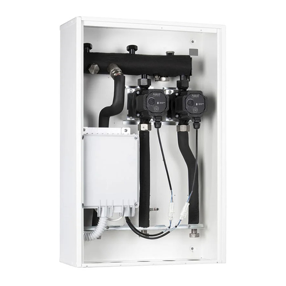
1.11 MAIN COMPONENTS. 1-10 DIM 2 Zone Key: 1 - Hydraulic manifold 2 - Drain fitting 3 - Zone 1 pump 4 - Electrical connection box 5 - Zone 1 ''Europa'' one-way valve 6 - Zone 2 pump 7 - Zone 2 ''Europa'' one-way valve 1-11 DIM 3 Zone Key:... - Page 13 1-12 DIM A-BT Key: 1 - Flow temperature thermometers 2 - Hydraulic manifold 3 - Drain fitting 4 - Zone 1 pump 5 - Zone 2 flow probe 6 - Zone 2 safety thermostat 7 - Electrical connection box 8 - Zone 2 3-way mixing valve 9 - Zone 2 mixing valve motor 10 - Zone 2 pump 11 - Zone 1 "Europa"...
-
Page 14: Use And Maintenance Instructions
USE AND MAINTENANCE INSTRUCTIONS 2.1 GENERAL WARNINGS. If the device must be deactivated temporarily, act directly on the main switch to power off the system and work safely • Attention: using any components that use electrical power requires the observation of some fundamental rules: - do not touch the device with wet or moist parts of the body;... -
Page 15: Checks And Maintenance
CHECKS AND MAINTENANCE - Check connection to a 230V-50Hz power mains via an omni-polar disconnector (magne- tothermal circuit breaker), correct L-N polarity and the earthing connection; - check that the magnetothermal circuit breaker is working properly; - make sure the central heating system is filled with water and that the pressure gauge indicates a pressure of 1-1.2 bar;... -
Page 16: Wiring Diagram Dim 2 Zone Erp
3.1 WIRING DIAGRAM DIM 2 ZONE ERP. Power supply 230 Vac 50 Hz Brown CENTRAL HEATING REQUEST OUTLET TO BOILER OR OTHER DIM CENTRAL HEATING REQUEST INLET FROM OTHER DIM OFF ON ZONES CONTROL UNIT ZONES SIGNAL STATE OUTLET FOR OTHER DIM... -
Page 17: Wiring Diagram Dim 3 Zone Erp
3.2 WIRING DIAGRAM DIM 3 ZONE ERP. Power supply 230 Vac 50 Hz Brown CENTRAL HEATING REQUEST OUTLET TO BOILER OR OTHER DIM CENTRAL HEATING REQUEST INLET FROM OTHER DIM OFF ON ZONES CONTROL UNIT ZONES SIGNAL STATE OUTLET FOR OTHER DIM By connecting the zone control Room Thermostats, it is necessary to eliminate the jumpers in the zones control unit on terminal board X9. -
Page 18: Dim H-Lt Erp Wiring Diagram
3.3 DIM H-LT ERP WIRING DIAGRAM. Power supply 230 Vac 50 Hz Brown CENTRAL HEATING REQUEST OUTLET TO BOILER OR OTHER DIM CENTRAL HEATING REQUEST INLET FROM OTHER DIM OFF ON ZONES CONTROL UNIT ZONES SIGNAL STATE OUTLET FOR OTHER DIM By connecting the zone control Room Thermostats, it is necessary to eliminate the jumpers in the zones control unit on terminal board X9. -
Page 19: Dim H-2Lt Erp Wiring Diagram
3.4 DIM H-2LT ERP WIRING DIAGRAM. Power supply 230 Vac 50 Hz Brown CENTRAL HEATING REQUEST OUTLET TO BOILER OR OTHER DIM CENTRAL HEATING REQUEST INLET FROM OTHER DIM OFF ON ZONES CONTROL UNIT ZONES SIGNAL STATE OUTLET FOR OTHER DIM By connecting the zone control Room Thermostats, it is necessary to eliminate the jumpers in the zones control unit on terminal board X9. -
Page 20: Dim Connection To Boiler Via Img Bus
3.5 DIM CONNECTION TO BOILER VIA IMG BUS. ONLY FOR BOILERS SET UP FOR DIGITAL COMMUNICATION WITH ZONE CONTROL UNIT. ZONES CONTROL UNIT DIM V2 Eliminate the jumper on terminal board X15 of the integrated P.C.B. SUPERIOR KW INTEGRATED P.C.B. Power supply 230 Vac 50 Hz... -
Page 21: Dim Connection To Boiler Via Zone
IMMERGAS MODELS WITH ZONE SIGNAL STATE OUTLET Terminal 21 allows you to activate the analogue dialogue with a strict exchange of information between boiler and DIM: - The DIM receives the zone signal state from the boiler;... -
Page 22: Dim Connections To On/Off Room Thermostats
3.7 DIM CONNECTIONS TO ON/OFF ROOM THERMOSTATS. WIRING DIAGRAM FOR DIM CONNECTION TO ON-OFF ROOM THERMOSTATS. ZONES CONTROL UNIT DIM V2 Key: AREA CONTROL ROOM S20-1 - Room thermostat zone 1 THERMOSTATS S20-2 - Room thermostat zone 2 S20-3 - Room thermostat zone 3 Note: All components represented in this diagram are optional. - Page 23 Example of hydraulic diagram for dividing zone 1 DIM into three portions. 3-10 External probe (optional) BOILER 1st DIM V2 3 ZONES Zones control unit DIM V2 Portion 1 of Portion 2 of Portion 3 of Zone 2 Zone 3 zone 1 zone 1 zone 1...
-
Page 24: Dim Connections To On/Off Room Thermostats And C.a.r
3.8 DIM CONNECTIONS TO ON/OFF ROOM THERMOSTATS AND C.A.R. / SUPER C.A.R.. REMOTE CONTROLS. Key: 3-11 ZONES CONTROL S20-1 - Zone 1 room thermostat (optional) UNIT DIM V2 This diagram represents an ex- S20-3 - Zone 3 room thermostat (optional) ample of the connection of the Super C.A.R. -
Page 25: Connection Between 2 Dim With Hydraulics In Parallel
3.10 CONNECTION BETWEEN 2 DIM WITH HYDRAULICS IN PARALLEL. 3-13 DIM TO BOILER BUS CONNECTION WIRING DIAGRAM. If the first DIM is connected to the boiler via IMG BUS and a second one is to be connected in parallel, connect the central heating request of the second DIM to the first one using input X11. - Page 26 Example of hydraulic diagram for parallel connection of 2 DIM. 3-15 External probe (optional) BOILER 1st DIM V2 3 ZONES 2nd DIM V2 3 ZONES External probe (optional) Zones Zones control unit control unit DIM V2 DIM V2 Zone 2 1st DIM Zone 31st DIM Zone 1 1st DIM Zone 2 2nd DIM...
-
Page 27: Dim Connection To Another Dim Or To Hercules Zone Kit With Hydraulics In Series
3.11 DIM CONNECTION TO ANOTHER DIM OR TO HERCULES ZONE KIT WITH HYDRAULICS IN SERIES. 3-16 With two DIM connected to each other in series, connect the central heating request of the second DIM to the HT input of the first one on the zone in which it has been connected. -
Page 28: Description Of Main Functions
3.12 DESCRIPTION OF MAIN 3.13 ZONE MANAGEMENT P.C.B. - LED H5 mixer opening zone 2 L.T. FUNCTIONS. The zone control unit can be configured using - LED H6 mixer opening zone 3 (optional) Three-way valves/anti-block pumps. the selector switches on the unit (14 Fig. 3-18), - LED H7 mixer closing zone 3 (optional) The device is supplied with a function that via which you can choose between the following... -
Page 29: External Temperature Probe (Optional)
H-LT and H-2LT version). Make sure the sys- room chrono-thermostat used, and can work in tem pressure and expansion vessel factory-set 35°C 50 °C combination with Immergas timer thermostats. pressure values are within the set limits; the The external probe must be electrically connected 40°C 62.5 °C factory-set value for the expansion vessel must as indicated in the Fig. -
Page 30: Technical Data
3.16 TECHNICAL DATA. DIM 2 zone DIM 3 zone DIM H-LT DIM H-2LT Maximum nominal pressure Maximum operating pressure °C Low-temperature circuit minimum set-point regulation temper- °C 25 or 35 25 or 35 ature Low-temperature circuit maximum set-point regulation temper- °C 50 or 75 50 or 75... - Page 32 Follow us Immergas Italia immergas.com Immergas S.p.A. 42041 Brescello (RE) - Italy Tel. 0522.689011 Fax 0522.680617 Certified company ISO 9001...