Table of Contents
Advertisement
Quick Links
Advertisement
Table of Contents
Troubleshooting

Related Manuals for SolarEdge SE1000

Summary of Contents for SolarEdge SE1000
-
Page 2: Disclaimers
The material furnished in this document is believed to be accurate and reliable. However, SolarEdge assumes no responsibility for the use of this material. SolarEdge reserves the right to make changes to the material at any time and without notice. You may refer to the SolarEdge web site (www.solaredge.com) for the most updated version. -
Page 3: Table Of Contents
Installation Workflow ......................12 Mounting and Connecting the SolarEdge Gateway ............13 Connecting the SolarEdge Gateway to AC ...............14 Chapter 3: Connecting the SolarEdge Gateway to the SolarEdge Installation ....15 Overview ..........................15 Connecting and Configuring the RS485 ................15 Verifying the Connection ....................19 Troubleshooting the RS485 Communication ..............19... - Page 4 Table of Contents Chapter 5: LCD – Status Screens and Setup Options ............32 Status Screens ........................32 Initial Gateway Status......................32 ID Status ..........................32 Server Communication Status ....................32 IP Status ..........................33 ZigBee Status ........................... 33 Wi-Fi Status ..........................33 Communication Ports Status ....................
-
Page 5: About This Guide
This guide describes the process of installing and configuring the SolarEdge Control and Communication gateway (also referred to as SolarEdge gateway). This guide assumes that the SolarEdge power harvesting system is already installed and commissioned. For additional information about how to install and commission the SolarEdge power harvesting system, refer to the relevant inverter or safety and monitoring system (SMI) installation guide. -
Page 6: Support And Contact Information
+972 73 240-3117 Before contacting, ensure you have the following information at hand: The communication method to the SolarEdge server The product serial number as appears on its label. The serial number can also be viewed in the ID Status screen, as described on page 32. -
Page 7: Handling And Safety Instructions
Handling and Safety Instructions Handling and Safety Instructions During installation, testing and inspection, adherence to the following handling and safety instructions is mandatory. The following safety symbols may be used in this document. Familiarize yourself with the symbols and their meaning before installing or operating the system. WARNING! Denotes a hazard. -
Page 8: Chapter 1: Introducing The Solaredge Control And Communication Gateway
The SolarEdge control and communication gateway expands the SolarEdge monitoring and control capabilities. It can be connected to SolarEdge and non-SolarEdge inverters, environmental sensors and revenue meters and can transfer the monitoring data to the SolarEdge monitoring server and optionally, to a non-SolarEdge logger. -
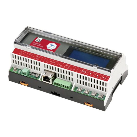
Page 9: Control And Communication Gateway Interfaces
Chapter 1: Introducing the SolarEdge Control and Communication Gateway Figure 2: Example of sensor connection to the SolarEdge gateway Control and Communication Gateway Interfaces Optional Optional Antenna1 Antenna2 Control RS485-1 SW1 RS485-2 RS232 USB (ZigBee) Enter (3) Down (2) LEDs:... -
Page 10: Lcd And Lcd-Menu Buttons
Enter (3): Selects a menu option or accepts a value change. Also used to enable LCD backlight. LEDs The front of the SolarEdge gateway has an LCD panel and three LEDs, as shown above: The gateway has three LED indicators, as follows: ... -
Page 11: Other Interfaces
Chapter 1: Introducing the SolarEdge Control and Communication Gateway Other Interfaces DC: used for the power supply input as described in Connecting the SolarEdge Gateway to AC on page 14. Sensors: enables connecting to external environmental sensors (refer to Chapter 4: Connecting Environmental Sensors (Optional) on page 22). -
Page 12: Chapter 2: Installing The Solaredge Gateway
UL 60950-2 standard. Transport and Storage Transport the SolarEdge gateway in its original packaging, without exposing it to unnecessary shocks. If the original package is no longer available, use a similar box, which can be closed fully. -
Page 13: Installation Guidelines
Recommended wire size: 20 AWG / 0.52 mm 50m (165 ft) The SolarEdge gateway power supply requires a socket outlet with a grid voltage of 100 V - 240 V. Protect the SolarEdge gateway from dust, wet conditions, corrosive substances and vapors. -
Page 14: Mounting And Connecting The Solaredge Gateway
► To mount the SolarEdge gateway on a wall: 1 Determine the mounting location. Leave clearance from all sides of the SolarEdge gateway for cover opening, cable connection and routing. 2 Open the clips at the rear of the gateway by pushing the clips outwards. -
Page 15: Connecting The Solaredge Gateway To Ac
2 Hook the two lower clips of the SolarEdge gateway onto the lower edge of the DIN rail. 3 Press the SolarEdge gateway upwards and snap it into the upper edge of the DIN rail. When on the rail, the clip "grips" the rail on both the top and bottom lips of the rail. -
Page 16: Chapter 3: Connecting The Solaredge Gateway To The Solaredge Installation
The SolarEdge control and communication gateway connects to the PV system installation using the RS485 communication option. The RS485 option enables creating a chain (bus) of up to 31 slave SolarEdge devices, connected to one master, which can be another SolarEdge device or the SolarEdge control and communication gateway. - Page 17 3 If the gateway is at the end of the RS485 chain, terminate the gateway by switching a termination dipswitch to ON. The switches in the SolarEdge gateway are marked SW1 for the RS485-1 port termination and SW2 for the RS485-2 port termination, as shown below:...
- Page 18 9 Connect all B, A and G pins in all inverters/SMI. The following figure illustrates this connection schema (the illustration applies to both inverters and SMI): SolarEdge Gateway Figure 11: Connecting SolarEdge devices (inverters or SMI) in a chain NOTE: Do not cross-connect B, A and G wires.
- Page 19 RS485-x Conf option in the Communication menu. One device must be set as the master on the RS485 bus. Any one of the SolarEdge devices may be the master (control and communication gateway, inverter, or SMI). If you connect the installation to the SolarEdge monitoring portal, the device used to connect to the server must be the master.
-
Page 20: Verifying The Connection
Verify that only one master is configured on the bus. 6 Close the inverter/SMI cover and start power production. Verify the connection of the Master to the SolarEdge monitoring portal, as described in Verifying the Connection, below. Verifying the Connection... -
Page 21: Rs485 Configuration Options
Device Type is used to select the specific port configuration. The following devices are supported: SolarEdge (default for RS485-1): Used when connecting to SolarEdge devices, such as: inverters, SMIs or other gateways. By default, all SolarEdge devices are pre-configured as slaves on the RS485-1 port. ... - Page 22 Device ID: The device ID is used to set the SolarEdge gateway device ID (MODBUS ID) when connecting to an external master device (for example, a non-SolarEdge logger), or to set the ID of the external device (for example, revenue meter).
-
Page 23: Chapter 4: Connecting Environmental Sensors (Optional)
-200 to 2000 W/m² You can view the sensor data in the Status window (see Sensors Status on page 34), and in the SolarEdge monitoring portal. This chapter describes how to connect sensors to the SolarEdge gateway and how to configure them. -
Page 24: Connecting Sensors To The Solaredge Gateway
For connection of the irradiance and temperature sensors available from SolarEdge refer to Sensor Connection Example on page 29. Sensors are directly connected to the SolarEdge gateway via the sensor interface connector. Use the supplied 7-pin terminal block. Figure 14 shows the location of the sensors connector on the gateway. - Page 25 I- V2 Vout Figure 15: Voltage sensor connection CAUTION! Excessive voltage on the sensor input can damage the SolarEdge gateway. Refer to input ranges specified in Appendix A: Technical Specifications on page 46. ► To connect a current sensor: Use a 3-wire cable for this connection. Recommended wire size is 0.52 mm /20 AWG with maximum length of 50m/164 ft.
-
Page 26: Configuring Environmental Sensors
Appendix A: Technical Specifications on page 46. Configuring Environmental Sensors Menus The SolarEdge gateway sensor interface is disabled by default. The following shows a hierarchical tree of the Sensors menu options: Sensors S e n s o r <... -
Page 27: Configuring The Sensors In The Solaredge Gateway
Set point: Enables entering two measurement signal values (voltage, current or temperature) Configuring the Sensors in the SolarEdge Gateway ► To enable the sensors in the SolarEdge gateway: 1 Press the Enter button until the following message is displayed: P l e a s e... - Page 28 To configure sensors in the SolarEdge gateway: NOTE: When using sensors provided by SolarEdge, enabling the sensors as described above automatically sets their configuration (available from SolarEdge gateway CPU version 2.07xx). If the CPU version is lower, configure the sensors as described below.
-
Page 29: Example Of Sensor Graph Configuration
However, if you want to include a partial range, set any value for the two points, as long as the points are within the SolarEdge gateway selected range. The SolarEdge gateway then extrapolates the sensor linear graph based on these two points. -
Page 30: Sensor Connection Example
Chapter 4: Connecting Environmental Sensors (Optional) Sensor Connection Example This section describes how to connect three of the sensors available from SolarEdge to the Control & Communication Gateway. For their full specifications refer to http://www.solaredge.com/files/pdfs/products/inverters/se_sensor_datasheet.pdf (for other recommended sensors and suppliers refer to http://www.solaredge.com/articles/se-supported-... - Page 31 Connect the wires to the 3-pin connector: Loosen the screws and insert the wire ends into the OUT, UB and GND pins. Connect the other ends of the wires to the external power supply and the SolarEdge gateway as follows: UB to V+ of the power supply...
- Page 32 P o i n t s If the CPU version of the SolarEdge gateway is 2.07xx and higher, the sensors are automatically configured. If the CPU version is lower, configure the sensors as described in To configure sensors in the SolarEdge gateway: on page 27.
-
Page 33: Chapter 5: Lcd - Status Screens And Setup Options
Server: The method of connection to the SolarEdge monitoring portal S_OK: The connection to the SolarEdge monitoring portal is successful (appears only if the inverter is connected to the portal). Status: Displays OK if the gateway established a successful connection and communication with the specified server port/device (LAN, RS485, ZigBee transceiver or RS232) If the OK status is not displayed, an error has occurred. -
Page 34: Ip Status
WLAN must employ the same SSID in order to communicate with each other. RSSI: The receive signal strength indication of the closest Wi-Fi in the SolarEdge system. L = low, M = medium, H = high and - = no signal. -
Page 35: Communication Ports Status
MPS: ZigBee multipoint slave (for a ZigBee router module) For a non-SolarEdge logger: SS: SunSpec For non-SolarEdge inverter readers and revenue meter reader, refer to http://www.solaredge.com/articles/se-supported-devices. ##: The total number of slaves detected on the specific port Sensors Status This window displays the status of up to three different sensors connected to the gateway. -
Page 36: Setup Menu Options
Chapter 5: LCD – Status Screens and Setup Options Setup Menu Options This section describes basic gateway configuration options. 1 Verify that the SolarEdge gateway is connected to a power outlet. 2 Press the Enter button until the following message is displayed: P l e a s e... - Page 37 E r r o r L o g W a r n i n g l o g This section describes how to use the LCD menus for configuring the SolarEdge gateway. Control and Communication Gateway Installation Guide - MAN-01-00132-1.2...
-
Page 38: Language
English. Communication 1 Select the Communication option to define and configure: The communication option used by the gateway to communicate with the SolarEdge monitoring portal The communication option used to communicate between multiple SolarEdge devices or other external non-SolarEdge devices, such as revenue meters or loggers. - Page 39 Chapter 5: LCD – Status Screens and Setup Options Communication: S e r v e r < L A N > L A N C o n f R S 4 8 5 – 1 C o n f < S > R S 4 8 5 –...
-
Page 40: Power Control
U p g r a d e C a r d Date and Time: Set the internal real-time clock. If connected to the SolarEdge monitoring portal, the date and time are set automatically and only time zone should be set. ... -
Page 41: Information
# # # # # # # # C P U : 0 0 0 2 . 0 3 3 6 . 0 0 0 0 ID: The SolarEdge gateway ID. 10 last digits of the S/N CPU: The communication board firmware version NOTE: Please have these numbers ready when you contact SolarEdge support. -
Page 42: Chapter 6: Setting Up Monitoring Through The Gateway (Optional)
This chapter describes how to set up this connection when the gateway is the connection point to the monitoring portal. The connection point can be any SolarEdge device. If it is the control and communication gateway, it should be the master on an RS485 bus. Otherwise, it should be a slave. -
Page 43: Creating An Ethernet (Lan) Connection
Chapter 6: Setting Up Monitoring through the Gateway (Optional) Creating an Ethernet (LAN) Connection Overview This communication option enables using an Ethernet connection to connect the SolarEdge gateway to the SolarEdge monitoring portal through a LAN. The SolarEdge gateway has an RJ45 connector for Ethernet communication. -
Page 44: Connecting And Configuring Lan
Set DNS: Set the DNS of the SolarEdge gateway according to the LAN settings. Set Server Addr: Set the IP address of the SolarEdge monitoring portal. This option is predefined in the SolarEdge gateway to specify the SolarEdge monitoring portal IP address and does not normally need configuration. -
Page 45: Troubleshooting Ethernet Communication
M e s s a g e > If S_OK is not displayed, use a method independent of the SolarEdge gateway to check whether the network and modem are operating properly. For example, connect a laptop to the Ethernet router and connect to the Internet. -
Page 46: Additional Connection Options
The Wi-Fi Communication Solution enables wireless communication between the SolarEdge inverter and a Wi-Fi router. A kit with a Wi-Fi module and an antenna is available from SolarEdge and is provided with a user, which should be reviewed prior to connection. It is available on the SolarEdge website at http://www.solaredge.com/files/pdfs/se_wifi_communication_solution_installation_guide.pdf... -
Page 47: Appendix A: Technical Specifications
FCC Part 15 class B, IEC61000-6-2, IEC61000-6-3 * Sold separately. See individual product specifications for supported locations. ** EU only *** For a list of recommended sensors and suppliers, refer to http://www.solaredge.com/articles/se-supported-devices. Control and Communication Gateway Installation Guide - MAN-01-00132-1.2... - Page 48 Appendix A: Technical Specifications Mechanical specifications: 161.6mm/6.36 in 90mm/3.54 in 62mm/2.44 in 90mm/3.54 in Figure 23: SolarEdge Gateway Mechanical Specifications Control and Communication Gateway Installation Guide - MAN-01-00132-1.2...