
Related Manuals for Ricoh PJ XL4540


Summary of Contents for Ricoh PJ XL4540
- Page 1 Furud-PJ1 RICOH PJ XL4540 (Y0A4) RICOH PJ WXL4540 (Y0A5) RICOH PJ LX3000ST(Y0A6) RICOH PJ LW3000ST(Y0A7) Field Service Manual December, 2015...
-
Page 3: Important Safety Notices
Important Safety Notices Important Safety Notices Prevention of physical injury 1. Before disassembling or assembling parts of the main machine and peripherals, make sure that the power cord of the main machine is unplugged. 2. The wall outlet should be near the machine and easily accessible. 3. -
Page 4: Laser Safety Information
Laser Safety Information Read through this document in its entirety and understand all warnings and precautions before attempting to operate the projector. • Do not turn the main power ON while any of the exterior covers are open. • Even if the purpose of the adjustment or confirming electrification, do not turn the main power ON holding down the safety interlock switch. -
Page 5: Laser Notice
Laser Notice • This Product is classified as Class 2 of IEC60825-1:2007 and also complies with 21 CFR 1040.10 and 1040.11 except for deviations pursuant to Laser Notice No.50, dated June 24,2007. (For USA) • IEC 60825-1:2014: CLASS 1 LASER PRODUCT - RISK GROUP 1. (For EU countries and Japan and China) Light source specification •... - Page 6 • This projector has built-in laser module. Possibly hazardous optical radiation emitted from this product. Do not stare into the beam. May be harmful to the eyes.
-
Page 7: Symbols, Abbreviations And Trademarks
Symbols, Abbreviations and Trademarks This manual uses several symbols and abbreviations. The meaning of those symbols and abbreviations are as follows: Screw Connector Trademarks • DLP is trademarks of Texas Instruments. • IBM is a trademark or registered trademark of International Business Machines Corporation. •... -
Page 8: Table Of Contents
TABLE OF CONTENTS Important Safety Notices........................... 1 Important Safety Notices..........................1 Prevention of physical injury......................... 1 Health safety conditions........................1 Observance of electrical safety standards..................1 Safety and Ecological Notes for Disposal....................1 Laser Safety Information.............................2 Safety Labels of This Machine........................2 Laser Notice..............................3 Light source specification.......................... - Page 9 Precautions..............................28 Do..................................28 Do not................................28 3. Replacement Special Tools..............................31 Equipment Needed............................32 Parts List................................33 Service Parts List............................33 Part Replacement..............................39 Dust Filters..............................39 Exterior Covers.............................40 Top Cover............................41 IO Cover.............................. 44 Front Cover............................45 Left Cover.............................46 Right Cover............................46 Keypad Board, Keypad Buttons.........................47 Main Board..............................
- Page 10 4. Adjustment Service Mode..............................73 How to enter the Service Mode........................73 Service Mode Settings..........................74 Adjustment................................ 76 Wheel Index Adjustment..........................76 Changing the LD/Projector Hours........................79 Calibration................................ 80 ADC Calibration............................80 Factory Reset..............................82 Factory Reset Procedure (OSD menu)....................... 82 Factory Reset Procedure (Service Mode)....................82 5.
- Page 11 Firmware update procedure......................104 Check system firmware version....................... 108 MCU Firmware Update..........................109 Upgrade Procedure..........................109 EDID Update..............................112 EDID Introduction............................112 Procedure..............................113 Setup Procedure (VGA&HDMI)...................... 113 EDID Key-In Procedure........................114 7. Detailed Description Laser................................121 Characteristics of Laser Light Source Projector..................121 Classification According to Light Source....................
-
Page 13: Product Information
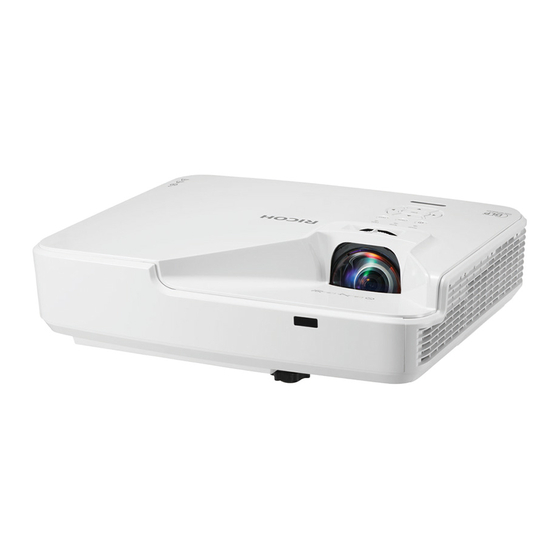
1. Product Information Overview Main Unit Control Panel Focusing Ring Ventilation (inlet) IR Receiver Ventilation (outlet) - Page 14 1. Product Information Speaker Power Socket Input / Output Connections Lens...
-
Page 15: Control Panel
Overview Control Panel Ind. Part Name Description Refer to the LED indicator of the projector power status. See Power LED page 85 "LED Indicators". Enter Confirm your item selection. Refer to the LED indicator of the projector temperature status. See Temp LED page 85 "LED Indicators". -
Page 16: Connection Ports
1. Product Information Ind. Part Name Description Power/Standby button Press the " " button on the control panel to turn On/Off the projector. IR Receiver Connection Ports 1. Computer-In/YPbPr Connector (PC Analog Signal/Component Video Input/HDTV/YPbPr) 2. HDMI2 Input Connector 3. HDMI1 Input Connector 4. -
Page 17: Remote Control
Overview Remote Control Ind. Part Name Description Transmitter Send signals to the projector. Picture Select the preset picture mode. Input Select the input source. AV Mute Momentarily turn off/on the audio and video. Four Directional Select items or make adjustments to your selection. Select Keys Auto Set Automatically synchronize the projector to the input source. - Page 18 1. Product Information Ind. Part Name Description Magnify +/- Adjust the part of the image magnification. (Digital Zoom) Shift to the "Light Source Power Mode" menu. Freeze Pause the screen image. Press again to resume the screen image. Menu Press "Menu" to launch the on screen display (OSD), or go back to the previous menu.
-
Page 19: Specifications
Projection System DLP 0.65" chip (WXGA) PJ XL4540/LX3000ST: 1024 x 768pixels (XGA) Resolution PJ WXL4540/LW3000ST: 1280 x 800pixels (WXGA) PJ XL4540/LX3000ST: F# 2.8, f = 7.15mm Lens PJ WXL4540/LW3000ST: F# 2.7, f = 7.51mm Light Source 3.5W Laser x 19pcs... - Page 20 Light Source Life 20,000h (ECO Mode) PJ XL4540/LX3000ST: 56.4 - 100 inch(XGA) Projection screen size PJ WXL4540/LW3000ST: 69.4 - 100 inch (WXGA) PJ XL4540/LX3000ST: 75 - 133 cm (XGA) Projection distance PJ WXL4540/LW3000ST: 78 - 112 cm (WXGA) *Focus range Speaker...
-
Page 21: Laser Diode Information
Description Type 3.5W laser diodes x 19 Normal mode: 10,000h LD life ECO mode: 20,000h @3.5W, 50% survival rate Pulse duration 1.08ms Lens PJ XL4540 PJ WXL4540 PJ LX3000ST PJ LW3000ST F-Stop F/2.8 F/2.7 Focus Length 7.15 7.51 Zoom Range... - Page 22 1. Product Information Mode Resolution V. Frequency [Hz] H. Frequency [Hz] 640 x 480 31.5 640 x 480 35.0 640 x 480 37.9 640 x 480 37.5 640 x 480 43.3 640 x 480 61.9 720 x 400 31.5 800 x 600 35.1 800 x 600 37.9...
- Page 23 Specifications Mode Resolution V. Frequency [Hz] H. Frequency [Hz] SXGA+ 1400x1050 65.3 UXGA 1600x1200 75.0 b. Extended wide timing Mode Resolution V. Frequency [Hz] H. Frequency [Hz] WXGA 1280x720 44.8 1280x800 49.6 1366x768 47.7 1440x900 59.9 WSXGA+ 1680x1050 65.3 c. Component signal Mode Resolution V.
-
Page 24: Hdmi Digital
1. Product Information HDMI Digital a. PC signal Mode Resolution V. Frequency [Hz] H. Frequency [Hz] 640 x 480 31.5 640 x 480 35.0 640 x 480 37.9 640 x 480 37.5 640 x 480 43.3 640 x 480 61.9 720 x 400 31.5 800 x 600... - Page 25 Specifications Mode Resolution V. Frequency [Hz] H. Frequency [Hz] 1280 x 960 60.0 QuadVGA 1280 x 960 75.2 SXGA+ 1400x1050 65.3 UXGA 1600x1200 75.0 b. Extended wide timing Mode Resolution V. Frequency [Hz] H. Frequency [Hz] WXGA 1280x720 44.8 1280x800 49.6 1366x768 47.7...
- Page 26 1. Product Information Mode Resolution V. Frequency [Hz] H. Frequency [Hz] 1080p 1920x1080 23.98/24 27.0 1920x1080 67.5 1920x1080 56.3 d. HDMI 1.4a mandatory 3D timing- Video Signal Mode Resolution V. Frequency [Hz] H. Frequency [Hz] Frame Packing 720p 31.5 720p 59.94/60 15.7 1080p...
-
Page 27: Installation Requirements
Installation Requirements Installation Requirements Environment/Power Requirements Operating temperature • Storage: -20°C to 60°C / -4°F to 140°F • Operating: 5°C to 40°C / 41°F to 104°F Altitude • Storage: 40,000ft • Operating; 0 to 2,500 ft for 5°C to 40°C 2,500 to 5,000 ft for 5°C to 35°C 5,000 to 10,000 ft for 5°C to 30°C Humidity... -
Page 28: Machine Dimensions
1. Product Information Machine Dimensions... -
Page 29: Installation
2. Installation Main Machine Installation The user must set this projector up. • About the handling of this machine, follow the contents with reference to Safety Information in the user manual. Accessory Check Description Q’ty Projector (Lens is included) Remote control (with Battery) Power cord VGA cable... -
Page 30: Precautions
2. Installation Description Q’ty User Manual (CD-ROM) Warranty Card Read This First (Paper) • Due to different applications in each country, some regions may have different accessories. Precautions Please follow all warnings, precautions and maintenance as recommended in this manual. •... - Page 31 Main Machine Installation • Ensure that the ambient room temperature is within 5°C to 40°C (41°F to 104°F). • Relative humidity is 20% to 80% • In areas susceptible to excessive dust and dirt. • Near any appliance generating a strong magnetic field. •...
- Page 32 2. Installation...
-
Page 33: Replacement
3. Replacement Special Tools Make sure that engineers are equipped with the following tools, which will be necessary in order to update the firmware, and to perform adjustments that are necessary after replacing the optical engine and other service parts. For details about what engineers should do, see page 72 "Required Action after Replacing Parts ". -
Page 34: Equipment Needed
3. Replacement Equipment Needed 1. Screw bit (+): 105 2. Screw bit (+): 107 3. Screw bit (-): 107 4. Hex sleeves 5 mm 5. Needle-nose pliers 6. Tweezers 7. Projector... -
Page 35: Parts List
Parts List Parts List Service Parts List Items Image Reference Optical Engine (with page 63 Focus Lever) Engine Unit page 65 Filter Wheel page 65 Combiner Unit page 65 Sheet for Heat Sink page 53... - Page 36 3. Replacement Items Image Reference Sheet for PSU page 57 Bottom Cover page 70 Top Cover (with Sponge) page 41 IO Cover page 44 Left Cover page 46 Right Cover page 46 Large Dust Filter Holder page 39 Large Dust Filter page 39 Small Dust Filter Holder page 39...
- Page 37 Parts List Items Image Reference Small Dust Filter page 39 Adjustable Foot page 69 Fan 1, 2 and 3 page 53 DMD Fan page 63 Rubber Vibration Isolator page 53 Interlock Switch page 57 Interlock Switch Holder page 57...
- Page 38 3. Replacement Items Image Reference Front IR Sensor page 62 Speaker (with Rubber) page 57 Front Cover page 45 page 57 Harness page 57 (PSU to Main Board) Harness page 63 (Laser Bank to LD Driver Board) Power Socket page 67 LD Driver Board page 56...
- Page 39 Parts List Items Image Reference Harness page 56 (LD Driver Board to Main Board) Keypad Board page 47 Keypad page 47 Keypad (Enter) page 47 IO Board page 52 Audio Board page 52 Harness page 57 (PSU to LD Driver Board)
- Page 40 3. Replacement Items Image Reference Harness page 52 (Main Board To IO Board) page 47 (Main Board to Key Pad Board) Main Board page 48...
-
Page 41: Part Replacement
Part Replacement Part Replacement • The laser safety level is class II. Appropriate laser safety eyewear must be worn if practicable while removing the top cover to do adjustment procedures. • Do not turn the main power ON while any of the exterior covers are open. •... -
Page 42: Exterior Covers
3. Replacement Remove the Small Dust Filter Holder [A] and Large Dust Filter Holder [B]. Pull out the filter [A] and [B] from the holders. Exterior Covers Location of screws... -
Page 43: Top Cover
Part Replacement Top Cover Remove 8 screws on left and right side ( x8). - Page 44 3. Replacement Remove 3 screws on the IO cover ( x3). Turn the projector upside down, then remove screw ( x1).
- Page 45 Part Replacement Open the top cover [A], and then disconnect the FFC ( x1). Top Cover [A] • There are five hooks on upper of front cover. Be careful not to break the books when removing the front cover.
-
Page 46: Io Cover
3. Replacement IO Cover Top Cover (page Remove screw on the upper side ( x1). Remove 5 screws (yellow circles) and 6 hex screws (red circles) on the back side ( x11), and then remove the IO cover [A]. -
Page 47: Front Cover
Part Replacement Front Cover Top Cover (page Remove 3 screws on Front Cover [A] ( Interlock Switch holder [A] ( x2), and IR Sensor [B] (2 hooks) -
Page 48: Left Cover
3. Replacement Left Cover Top Cover (page Left Cover [A] ( Right Cover Top Cover (page... -
Page 49: Keypad Board, Keypad Buttons
Part Replacement Right Cover [A] ( : flat screws x 3) Keypad Board, Keypad Buttons Top Cover (page Keypad Board [A] ( Separate keypad module into Keypad Board [A] and Keypad buttons [B]. -
Page 50: Main Board
3. Replacement Remove the FFC [A] from Main Board to Keypad Board ( x1). Main Board Top Cover (page IO Cover (page Top Shielding [A] ( Make sure not to forget to peel off the black sheet [A] before removing the top shielding. - Page 51 Part Replacement IO Shielding [A] ( Main Board [A] with bracket ( x4, all connectors)
- Page 52 3. Replacement There is a connector [A] at the back side of the main board. Pull the main board upward, and then disconnect it ( x1). Separate the bracket [A] and Main Board [B] ( x2).
-
Page 53: Connection List
Part Replacement Connection List Item Name on board Key feature Figure None Black wire tube (16 pin) (to PSU) P/W INDEX Compose of Red/Black/ (to Photo Sensor for Filter White Wire(3 pin) Wheel) FFC cable (to Filter Wheel) P/W INDEX Compose of Red/Black/ (to Photo Sensor for White Wire(3 pin) -
Page 54: Io Board, Audio Board
3. Replacement Item Name on board Key feature Figure Compose of Red/Black Wire(2 pin) (to Speaker) LD IF FFC cable (To LD Driver Board) Compose of Red/Blue/ DMD FAN Black Wire (3 pin) Compose of Red/Yellow/ Sys FAN Black Wire(3 pin) IO Board, Audio Board The IO Board and Audio Board are attached on Main Board. -
Page 55: Fan 1, Fan 2, And Fan 3
Part Replacement Separate IO Board and Audio Board from Main Board ( x2). Audio Board [A] ( IO Board [B] ( Fan 1, Fan 2, and Fan 3 Top Cover (page... - Page 56 3. Replacement Disconnect the "SYS FAN1, 2 and 3" Connector on Main Board ( x3). Peel off the black sheet for heat sink [A]. Remove the Fan 1, Fan 2 and Fan 3.
-
Page 57: Notes On Installation
Part Replacement Rubber Vibration Isolator [A] Notes on Installation • Attach the fans so that the marking comes to the position shown in the following figure. • Attach the Rubber Vibration Isolator [A] to the bottom cover guide as shown in the following figure. -
Page 58: Ld Driver Board
3. Replacement LD Driver Board Top Cover (page Bracket [A] ( LD Driver Board [A] (... -
Page 59: Speaker
Part Replacement Speaker Top Cover (page Remove the ground wire screw and disconnect "SPK" connector on Main Board.! ([A]: Speaker) Speaker [A] Interlock Switch, PSU Top Cover (page Front Cover (page LD Driver Board (page... - Page 60 3. Replacement Bracket for PSU [A] ( Disconnect the Interlock Switch connector [A] on the PSU ( x1). Remove the Interlock Switch [A]...
- Page 61 Part Replacement Remove the black tape [A] of Interlock Switch. Separate the Interlock Switch [A] and Holder [B] (2 hooks). PSU [A] ( 3 hex screws, 1 round screw...
- Page 62 3. Replacement • When removing the PSU, put the sheet [A] out of the way so that the parts on the PSU board are not caught by the sheet. • Be careful not to scratch the lens [A] surface.
- Page 63 Part Replacement 2 harnesses ( Sheet for PSU [A]...
-
Page 64: Front Ir Sensor
3. Replacement Front IR Sensor The connector [A] is too large to pass through between PSU [B] and harness guide. So first you have to remove PSU. Top Cover (page Disconnect the "F IR" connector on Main Board ( x1). Front Cover (page LD Driver Board... -
Page 65: Notes On Installation
Part Replacement Peel the sheet [A] off, and then remove the Front IR Sensor [B]. Notes on Installation Attach the harness to guide (three red circles as shown) on bottom cover. Optical Engine, DMD Fan Optical Engine [A] is comprised of the following parts: 1. - Page 66 3. Replacement IO Cover (page 44 "IO Cover") Main Board, IO Board, Audio Board (page page Optical Engine [A] (...
-
Page 67: Engine Unit, Filter Wheel, Combiner Unit
Part Replacement Sponge seal [A] DMD Fan with bracket [A] ( Separate the DMD Fan [A] and Bracket [B]. Engine Unit, Filter Wheel, Combiner Unit Optical Engine [A] (page... - Page 68 3. Replacement Filter Wheel Cover [B] ( x2). Filter Wheel [A] ( x2).
-
Page 69: Power Socket
Part Replacement Separate the Combiner Unit [A] and Engine Module [B]. Notes on Attaching the Filter Wheel After attaching the cover, pull out the FFC until the black line appears. If the FFC is loose inside the cover, it might come into contact with the filter wheel, causing an error. Power Socket Exterior Covers (page... - Page 70 3. Replacement Bottom Shielding [A] ( Socket with bracket [A] (...
-
Page 71: Adjustable Foot
Part Replacement Remove the harness from the 2 hooks as shown; Separate bracket [A] and Power Socket [B]. Adjustable Foot There are three adjustable feet; there are 1 on the front and 2 on the rear. Rotate the adjustable foot [A] counterclockwise and remove it. No nut attached on the bolt so turn the Adjustable foot counterclockwise and remove it. -
Page 72: Bottom Cover
3. Replacement Bottom Cover Remove the all units on Bottom Cover. Refer to the procedures of the relevant service parts. (page 31 "Replacement") Adjustable Foot (page Cover for an Opening Area of Bottom Surface [A] ( Rubber for an Opening Area of Bottom Surface [A]. - Page 73 Part Replacement Theft Protection Hook [A] ( Remove the Suspension Bracket [A] (...
-
Page 74: Required Action After Replacing Parts
3. Replacement Required Action after Replacing Parts After replacing parts, execute the related items shown in the table below. Changed parts Action after repair Reference Main Filter Engine Combiner Unit Board Wheel Unit Firmware Update*1 page 97 Wheel Index Adjustment page 76 Factory Reset page 82... -
Page 75: Adjustment
4. Adjustment Service Mode How to enter the Service Mode Turn on the projector. Press the [Power [1]] key, and then, press the [Left [2]], [Right [3]], and [Menu [4]] keys sequentially to enter the service mode. You can enter the service mode by using the remote controller. The service mode menu appears. -
Page 76: Service Mode Settings
4. Adjustment Service Mode Settings Setting Items Descriptions Over Temp Use this to display the high temperature error. Use this to display the details of fan error, such as fan name Fan Lock error occurred and fan speed. Use this to display the details of LD error, and reset/change LD Fail the LD counter in each power mode. - Page 77 Service Mode Setting Items Descriptions Red PWM DFU*1 Green PWM DFU*1 Blue PWM DFU*1 Yellow PWM DFU*1 LD (1to3) Enable DFU*1 LD Demo Mode DFU*1 LD Calibration CALIBRATION Use this to execute the LD calibration. CALIBRATION Reset Use this to reset the value of calibration data. CALIBRATION DATA Use this to display the detailed value of LD calibration.
-
Page 78: Adjustment
4. Adjustment Adjustment Wheel Index Adjustment After replacing the main board, combiner unit, filter wheel, or engine unit, the Wheel Index Adjustment should be done. Environment • Test pattern: Full Color Pattern [A], 64 gray RGBW [B] Connect the projector to PC with HDMI or VGA cable, and then, turn ON the main power. Enter the Service mode. - Page 79 Adjustment Select [Wheel Index], and then press [Enter] key. Select the display mode, and then, using the [Left] or [Right] key, adjust the R/G/B and gray gradations until they are correct and satisfactory. Both "P-Wheel Index" and "F-Index" are well adjusted. Inspection item •...
- Page 80 4. Adjustment...
-
Page 81: Changing The Ld/Projector Hours
Changing the LD/Projector Hours Changing the LD/Projector Hours After replacing the main board, or combiner unit, you must rewrite the LD/projector operation hours. Write down the LD/projector operation hours before the replacement and put back the same value after replacing. Enter the Service mode. -
Page 82: Calibration
• Test equipment: PC support HDTV resolution • Test signal: 1024x768@60Hz (For RICOH PJXL4540/LX3000ST) 1280x800@60Hz (For RICOH PJ WXL4540/LW3000ST) • Test pattern: 94%White(up) / 6% Black (down) • Calibration pattern should be in full screen mode. • Input the signal from the VGA port Connect VGA1-in port [A]. - Page 83 Calibration Select "VGA-1 ADC Calibration" to perform the calibration. When calibration is completed, "OK" appears on the screen. Connect VGA2-in port [A]. Select "VGA-2 ADC Calibration" When calibration is completed, "OK" appears on the screen. Criteria If there is noise on the screen, the product is considered as failure product. There should be no unusual conditions, such as lines on the screen.
-
Page 84: Factory Reset
4. Adjustment Factory Reset Factory Reset allows you to erase all OSD menu settings and restore the default setting (except the service mode). There are two ways to do Factory Reset. Either way, the settings to be reset are the same. After replacing the main board, Factory Reset must be done. - Page 85 Factory Reset Select [Factory Reset], and then press the [Enter] key. Select [Yes], and then press the [Enter] key.
- Page 86 4. Adjustment...
-
Page 87: Troubleshooting
5. Troubleshooting LED Indicators [A] : Power LED [B] : TEMP LED [C] : LIGHT LED Message Power LED TEMP LED LIGHT LED (Red or Blue) (Red) (Red) Standby (Input power cord) (Red) Normal (Power on) (Blue) Flashing Red Powering up (Warming up) (1.0sec.) Flashing Red Power off (Cooling Down) - Page 88 5. Troubleshooting Message Power LED TEMP LED LIGHT LED (Red or Blue) (Red) (Red) Error (Light source failed On Event) Error (Light source failed On Standby) Flashing Error (Fan failed On Event) 3sec. Flashing Error (Fan failed On Standby) 3sec. Flashing Error (Filter Wheel fail / Striking Light source Fail On Event)
-
Page 89: Troubleshooting
Troubleshooting Troubleshooting First, check the items below. • Make sure you have connected the projector properly to the peripheral equipment. • Make sure all equipment is connected to an AC outlet and the power is turned on. • If the projector does not project an image while being operated with a computer, restart the computer. - Page 90 5. Troubleshooting Symptom Solution procedure 1. Ensure all connectors are securely connected and are not broken. 2. Check LED status. If Temp LED lit Red, Lamp LED lit Red • Check the Interlock Switch. If Temp LED flashing Red: 0.5 sec. •...
- Page 91 Troubleshooting Symptom Solution procedure 1. Do "Reset" under "Settings" of the OSD Menu. 2. Execute LD Calibration. 3. Adjust Wheel Index. Color Unusual 4. Check the Main Board. 5. Check the Filter Wheel Module. 6. Check the Combiner Module. 1. Ensure the projection screen without dirt. 2.
- Page 92 5. Troubleshooting Symptom Solution procedure 1. Ensure that the signal cables and source are work as well. 2. Ensure the projector is not in "Mute" mode. Audio Unusual 3. Check the Main Board. 4. Check the Speaker. 1. Ensure the using 3D glasses is good. 2.
-
Page 93: Test And Inspection
Test and Inspection Test and Inspection Test Equipment Needed • PC support HDTV resolution. • Blue-ray DVD player supports "S-Video", "3D source files","HDMI", and "Video". Recommended Test Condition • Ambient brightness: Dark room less than 2 lux. • Product must be warmed up for 3 minutes. •... -
Page 94: Vga Port Test
5. Troubleshooting VGA Port Test Pixel Specifications and Criteria A stands for "Zone A". B stands for "Zone B". Active area = Zone A + Zone B For PJ WXL4540 / PJ LW3000ST Order Symptom Pattern Criteria Blue 60 1. ≤ 4 visible dark blemishes are allowed in the active area (Zone A + Zone B). -
Page 95: Audio Performance Test
Test and Inspection For PJ XL4540 / PJ LX3000ST Order Symptom Pattern Criteria Blue 60 1. ≤ 4 visible dark blemishes are allowed in the active area (Zone A + Zone B). Dark Blemish 2. No blemish will be > 1.5"... -
Page 96: Video Performance Test
5. Troubleshooting Check the sound from speaker. Criteria Check whether "Volume" is working properly. Video Performance Test • Test equipment: DVD player • Test signal: Video Criteria Check any unsatisfactory color, line distortion or any noise on the screen. Check the sound from speaker. HDMI Performance Test •... -
Page 97: Usb Performance Test
Test and Inspection USB Performance Test • Test equipment: USB Memory with video files Plug USB memory into USB port, and then search multimedia. Select "USB Disk" on OSD menu, and then click "Video" to test. Criteria Check whether sound and video is satisfactory. Check points Check item Check point... - Page 98 5. Troubleshooting...
-
Page 99: Firmware Update
6. Firmware Update System Firmware Update Equipment Needed Software • DLP Composer Lite • Firmware (*.img) • HD26FlashDeviceParameters • Download "DLP Composer Lite" and "HD26FlashDeviceParameters" from website that provides the relevant tools for maintenance. Hardware 1. Projector 2. Power cord 3. - Page 100 6. Firmware Update Click "Next". Read "License Agreement", and then choose "I accept and agree to be bound by all the terms and conditions of this License Agreement" and click "Next".
- Page 101 System Firmware Update Click "Next". Click "Next". Click "Next".
-
Page 102: Get Into Firmware Download Mode
6. Firmware Update The program is executing "installing" status. Click "Finish". Get into firmware download mode Set up the following procedure. While holding down the "Enter" key, then plug in the power cord. -
Page 103: Usb Driver Update Procedure
System Firmware Update After the Power LED lights pink, and the Lamp and Temp LEDs light red, then release the "Enter" key as shown in the photo below. USB driver update procedure Execute "Install DLP Device Drivers" in the start menu. - Page 104 6. Firmware Update Select "Jungo WinDriver (WinVista/Win7)", then click "install". • If OS is 64bit, select "Microsoft WinUSB". Click "Next".
-
Page 105: Connect The Projector To The Pc
System Firmware Update Click "Finish". Connect the projector to the PC Enter the firmware download mode. (page 100) Connect the Projector and PC with a mini USB cable. The Found New Hardware Wizard appears. Select "No, not this time", then click "Next". -
Page 106: Firmware Update Procedure
6. Firmware Update Select "Install the software automatically (Recommended)", then click "Next". Click "Finish". Firmware update procedure Execute the "DLP Composer Lite **" file. Select the file "V1FlashDeviceParameters". - Page 107 System Firmware Update Put "V1FlashDeviceParameters" file into the folder where you setup "DLP Composer Lite **". Click "Edit" and "Preferences".
- Page 108 6. Firmware Update Click "Communications" and select "USB" then click "OK". Choose "Flash Loader" and click "Browse" to search the firmware file (*.img) and click "Open".
- Page 109 System Firmware Update Select the item "Skip Boot Loader Area" and select "64KB" then click "Reset Bus" to erase the flash memory. If the firmware is ready, click "Start Download" to execute the firmware update. Click "Yes" to erase the flash memory. . It takes about several minutes, the firmware update process is finished, "Download completed"...
-
Page 110: Check System Firmware Version
6. Firmware Update Unplug the USB cable and power cord. Check system firmware version Re-plug in the power cord, and then restart the projector. Get into the Service Mode. (page Check the system firmware version [A]. -
Page 111: Mcu Firmware Update
MCU Firmware Update MCU Firmware Update Upgrade Procedure Equipment Needed • NuMicro ISP Programming Tool • Firmware (*.isp) • Projector • Power cord • Female to female RS232 Cable • PC or Laptop Plug in the power cord, connect the projector to PC with RS232 cable. Execute the "NuvoISP.exe"... - Page 112 6. Firmware Update Click the "File", and then select "Load Project". Select the firmware file, and then click "open". Click"Start".
- Page 113 MCU Firmware Update After the "PASS" appeared, close the window. Check if the MCU firmware [A] is updated on Service Mode.
-
Page 114: Edid Update
6. Firmware Update EDID Update EDID Introduction Extended Display Identification Data is a VESA standard data format that contains basic information about a display device and its capabilities, including vendor information, maximum image size, color characteristics, factory pre-set timings, frequency range limits, and character strings for the monitor name and serial number. -
Page 115: Procedure
EDID Update Procedure Setup Procedure (VGA&HDMI) Connect all ports. 1. Connect P1 of Fixture Board [A] to COM Port of PC/Laptop with RS232 cable. 2. Connect P3&P4 of Fixture Board to VGA-in port of projector with VGA cable. 3. Connect P5 of Fixture Board to HDMI1 port of projector with HDMI to DVI cable. 4. -
Page 116: Edid Key-In Procedure
6. Firmware Update EDID Key-In Procedure Execute EDID Program. (1) Click "EDID" to execute EDID program. Process (1) Select the COM Port which you are using. (2) Click "Model". (3) Select the source file (*.ini). (4) Click "Open". - Page 117 EDID Update (5) Enter the Serial Number next to "Unit No.". (6) In "Write Source Select", select "VGA1" and "HDMI1". (7) Click "Program". (8) Click "OK".
- Page 118 6. Firmware Update (9) Click "OK". (10) Click "OK".
- Page 119 EDID Update (11) Connect P5 of Fixture Board to HDMI port 2 of projector with HDMI to DVI cable, and then click "OK".
- Page 120 6. Firmware Update When the EDID program is completed, a message "OK" will appear on the screen. Read EDID "VGA" information. In the Read, select "Analog" and "Trans", and then click "Read". EDID information will show the result. Read EDID "HDMI" information. In the Read, select "Digital"...
- Page 121 EDID Update...
- Page 122 6. Firmware Update...
-
Page 123: Detailed Description
Disadvantages and Challenges 1. Laser light source is expensive. 2. Compliance with laws and regulations in different countries. Class definition of laser equipment. Compliance with Ricoh regulations. 3. Ensuring safety and education of service representatives Classification According to Light Source... -
Page 124: Optical Mechanism
7. Detailed Description Light Source/ Light Collection image Characteristic Method • Instant on • Long lifetime • Maintenance free 2. Laser / LED • Brightsync and very high color Hybrid rates • LED Etendue* will limit brightness 2000-3500L • Instant on •... -
Page 125: Optical Engine Component
Laser The blue light passes without modification. To use the blue light as is, there is the blue wraparound path [C]. The filter wheel [G] creates the red light from the yellow light. Red, yellow, green, and blue lights reach the DMD [F]. *Afocal lens, without convergence, transmits light signal to a distant point as a parallel light. - Page 126 7. Detailed Description Combiner Module Combiner module is comprised of the heat sink [A], heat pipe [B], laser bank [C], filter wheel [D], and phosphor wheel [E]. Phosphor wheel The phosphor wheel [A] is divided into 3 segments comprised of the blue transparency, yellow phosphor, and green phosphor.
-
Page 127: Projection Light
Laser It is divided into 4 segments comprised of green, blue (diffuser), red, and yellow (transparent). Laser bank Each laser bank is comprised of 24 laser diodes (4, 5, 5, 5 and 4) and is cooled by the heat pipe. Projection Light Blue laser light turns into a diffused light in its optical path and then its coherence is lowered as it passes through the filter wheel and other parts, so the projection light is not dangerous. -
Page 128: Light
7. Detailed Description Light This picture shows the relationship between the visible light and wave length in units of nanometer. Wavelength • The light energy (E) can be calculated by the formula E=a (constant)/wavelength, and the shorter the wavelength, the higher the energy. •... - Page 129 MEMO...
- Page 130 MEMO...