Table of Contents
Advertisement
Quick Links
Advertisement
Table of Contents
Troubleshooting

Related Manuals for SolarEdge WIFI-GW

Summary of Contents for SolarEdge WIFI-GW
- Page 1 Installation Guide Wi-Fi Gateway, Wi-Fi Repeater Model: WIFI-GW Version 1.1...
-
Page 2: Disclaimers
SolarEdge reserves the right to make changes to the material at any time and without notice. You may refer to the SolarEdge web site (www.solaredge.com) for the most updated version. All company and brand products and service names are trademarks or registered trademarks of their respective holders. -
Page 3: Emission Compliance
Emission Compliance The images contained in this document are for illustrative purposes only and may vary depending on product models. Emission Compliance This equipment has been tested and found to comply with the limits applied by the local regulations. These limits are designed to provide reasonable protection against harmful interference in a residential installation. -
Page 4: Revision History
Disclaimers 3 Changes or modifications not expressly approved by the party responsible for compliance may void the user’s authority to operate the equipment. NOTE Interferences may occur when the Wi-Fi Gateway and repeater are installed near other 2.4 GHz emitting devices (such as dual technology PIR detectors used in alarm systems, microwave ovens, etc.). -
Page 5: Table Of Contents
Contents Disclaimers Important Notice Emission Compliance Support and Contact Information About This Guide Chapter 1: Overview Connection Options Package Contents Chapter 2: Wi-Fi Gateway Interfaces Push-button LED Indications Chapter 3: Connection and Configuration Chapter 4: Status, Errors and Troubleshooting Wi-Fi Gateway and Repeater Technical Specifications (Europe &... -
Page 6: Support And Contact Information
Support and Contact Information 5 Support and Contact Information If you have technical problems concerning SolarEdge products, please contact us: Support Center: https://www.solaredge.com/service/support Country Phone E-Mail support@solaredge.net.au Australia (+61) 1800 465 567 support- APAC (Asia Pacific) 073 240 3118 asia@solaredge.com... - Page 7 System configuration information, including the type and number of modules connected and the number and length of strings. The communication method to the SolarEdge server, if the site is connected. The inverter software version as appears in the status screen.
-
Page 8: About This Guide
SolarEdge power harvesting system. This guide describes how to install and set up the Wi-Fi Gateway and Wi-Fi Repeater(s). This guide assumes that the SolarEdge power harvesting system is already installed and commissioned. For additional information about how to install and commission the SolarEdge power harvesting system, refer to the relevant installation guide. - Page 9 (Europe & APAC) on page 32 provides the electrical and mechanical specifications of the Wi-Fi Gateway. For further information, datasheets and the most up-to-date certifications for various products in different countries, please visit the SolarEdge website: www.solaredge.com. Wi-Fi Gateway and Repeater Installation Guide MAN-01-00559-1.1...
-
Page 10: Chapter 1: Overview
Chapter 1: Overview 9 Chapter 1: Overview The Wi-Fi communication option enables connecting a SolarEdge inverter to the SolarEdge monitoring platform. The Wi-Fi Gateway collects all inverters monitoring data using dedicated Wi-Fi and connects to the monitoring platform through Ethernet. -
Page 11: Connection Options
Connection Options The Wi-Fi Gateway and repeater can be used with SolarEdge inverters with SetApp configuration, version 4.6.xx and later. Figure 1: The Wi-Fi Gateway/ Repeater Connection Options Terminology This document uses the following terms for describing the communication flow:... - Page 12 Chapter 1: Overview 11 Single Inverter, Wireless Connection The inverter is wirelessly connected to the monitoring platform via the Wi-Fi Gateway. The Wi-Fi Gateway is connected to the home router via Ethernet. One or two optional repeaters extend the Wi-Fi range. Figure 2: Single inverter, wireless connection Multiple Inverters Multiple devices, RS485 Master/ Slaves...
- Page 13 Connection Options Figure 3: Multiple inverters, wired connection Multiple devices, Wi-Fi Point to Multi-point This configuration enables connecting multiple devices wirelessly. The Wi-Fi Gateway is connected to the home router via Ethernet. Several inverters can be connected to a single Wi- Fi Gateway.
-
Page 14: Package Contents
Ethernet cable ü ü Installation guide NOTE Keep the device packaging as you will use the QR code on the labels for configuration. (1) For connecting additional inverters, an antenna is available from SolarEdge Wi-Fi Gateway and Repeater Installation Guide MAN-01-00559-1.1... -
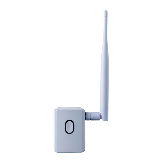
Page 15: Chapter 2: Wi-Fi Gateway Interfaces
Chapter 2: Wi-Fi Gateway Interfaces Chapter 2: Wi-Fi Gateway Interfaces Figure 5: Wi-Fi Gateway interfaces Push-button The Wi-Fi Gateway is equipped with a configuration push- button, which is used for: Accessing troubleshooting mode. Refer to Troubleshooting on page 27. Enabling a mobile device (for example: smart phone, tablet) to access a web page for maintenance. -
Page 16: Led Indications
Chapter 2: Wi-Fi Gateway Interfaces 15 LED Indications The following table describes the LED color indications for the Wi-Fi Gateway or repeater: Color Status Indication No power Internal error During factory reset , or Red Pairing between the inverter Fast blinking and the Wi-Fi Gateway or the (5 sec.) closest repeater to the... - Page 17 LED Indications Color Status Indication During pairing of repeater and uplink gateway, and Fast blinking Pairing between the repeater (5 sec.) and the Wi-Fi Gateway or the closest uplink repeater to the inverter succeeded. Communication between the Wi-Fi Gateway and the monitoring platform is OK, Blinking No communication between...
- Page 18 Chapter 2: Wi-Fi Gateway Interfaces 17 Color Status Indication At least one inverter is connected to the Wi-Fi Gateway/ repeater. No communication between the Wi-Fi Gateway/repeater and the monitoring platform, Flashing No communication between the Wi-Fi Gateway/repeater and the downlink repeater/ inverter.
-
Page 19: Chapter 3: Connection And Configuration
Chapter 3: Connection and Configuration Chapter 3: Connection and Configuration This section describes basic connection and configuration of one or more inverters. You can connect the inverter(s) using just the Wi-Fi Gateway. However, one or two repeaters may be required to extend the Wi-Fi range. - Page 20 Chapter 3: Connection and Configuration 19 To connect a Wi-Fi Gateway and Repeater(s): The following steps describe pairing a Wi-Fi Gateway (and a repeater if required), with the inverter and connecting the inverter to the monitoring platform via Wi-Fi. It is recommended to perform the pairing when the devices are close to each other.
- Page 21 3. Use SetApp to pair the Wi-Fi Gateway (and repeater if required) with the inverter: a. Select Communication è Wi-Fi. The Wi-Fi screen is displayed: Wi-Fi › Connect to SolarEdge Wi-Fi Gateway › Connect to SolarEdge Wi-Fi Gateway and Repeater/s ü ...
- Page 22 Chapter 3: Connection and Configuration 21 c. Wait for the message All Device(s) Scanned to appeaer on the SetApp screen. d. Do one of the following: To complete the installation now, select Continue Now. The inverter attempts to establish a connection with the Wi-Fi Gateway and the monitoring platform.
- Page 23 Chapter 3: Connection and Configuration troubleshooting, refer to "Status, Errors and Troubleshooting " on page 23. g. If required, repeat the above steps for additional inverters. Wi-Fi Gateway and Repeater Installation Guide MAN-01-00559-1.1...
-
Page 24: Chapter 4: Status, Errors And Troubleshooting
Chapter 4: Status, Errors and Troubleshooting 23 Chapter 4: Status, Errors and Troubleshooting This section describes how to use the Wi-Fi Gateway push button to check the system status, edit parameters, troubleshoot errors, or reset the device. Accessing the Wi-Fi Gateway Web Page You can check or edit Wi-Fi Gateway parameters by accessing a web page. - Page 25 Chapter 4: Status, Errors and Troubleshooting To access the web-page when the Wi-Fi Gateway is in Operational mode: 1. Open a browser on your mobile device (smart-phone, tablet). 2. Enter the following: IP address: 192.168.5.1. Username: Admin Password: the 4 last digits of the Wi-Fi Gateway serial number (printed on the QR label) Authentication type (printed on the label) The following is a web page example of the Wi-Fi Gateway...
- Page 26 Chapter 4: Status, Errors and Troubleshooting 25 To access the web-page when the Wi-Fi Gateway is in Maintenance mode: 1. Press the push-button for more than 4 seconds. The Wi-Fi Gateway attempts to establish connection with a mobile device. 2. On your mobile device, access the list of Wi-Fi networks. The list will now contain one or more access points, as follows: For Wi-Fi Gateway: SEDG-GW-MAINT[xx]...
- Page 27 Chapter 4: Status, Errors and Troubleshooting Figure 7: Web page (Maintenance mode) Wi-Fi Gateway and Repeater Installation Guide MAN-01-00559-1.1...
-
Page 28: Troubleshooting
Chapter 4: Status, Errors and Troubleshooting 27 Troubleshooting You can check for connectivity errors by observing the LED indications in troubleshooting mode. This functionality is unavailable during pairing or if pairing failed. To activate the error display: Short-press the push-button (< 1 sec). The LED color changes in the following sequence: Color1 blinks è... - Page 29 Chapter 4: Status, Errors and Troubleshooting Error Description Troubleshooting Color 1 Color 2 Check the cable pinout assignment and cable connection. Refer to Creating an disconnected Ethernet (LAN) Connection in the inverter installation guide . Orange No downlink Wi-Fi connection detected by the repeater.
- Page 30 If internet access is Internet Ping unavailable, contact your Failed (to Orange Orange Google IT admin or your internet server) service provider. If internet access is available, contact SolarEdge Support. Wi-Fi Gateway and Repeater Installation Guide MAN-01-00559-1.1...
- Page 31 Chapter 4: Status, Errors and Troubleshooting Error Description Troubleshooting Color 1 Color 2 Ping or connection to SolarEdge server failed. Check with your network administrator whether a Server Ping Orange Blue firewall or another device Failed is blocking transmission. If internet access is available, contact SolarEdge Support.
- Page 32 Chapter 4: Status, Errors and Troubleshooting 31 Factory Reset Factory Reset is used to reset all the parameters to factory values, and erase the device list. Use this functionality to select a new Wi-Fi band in case no device can be connected, or multiple connection interruptions.
-
Page 33: (Europe & Apac)
Wi-Fi Gateway and Wi-Fi Repeater Technical Specifications (Europe & APAC) Model: WIFI-GW Performance Unit Transmit power (Max) Receiver -94 to -69 sensitivity EIRP with Antenna Outdoor (LOS) 400 / 1300 m/ft range 50 /160 m/ft Indoor range Frequency Band 2412 - 2472... - Page 34 Wireless LAN Standards 802.11b/g/n 802.11b - DSSS-CCK 802.11g - OFDM Modulation 802.11n - HT modulations MCS0-7 Data rates 1 - 72 Mbps Environmental Operating -20 to +60 / -4 to +140 °C / °F temperature Storage -20 to +60 / -4 to +140 °C / °F temperature Relative humidity...
- Page 35 Power Supply AC Voltage 100-240 (nominal) AC frequency 50/60 (nominal) Max Input Current Standard Compliance Safety IEC/EN 62368-1 EN301 489-1; EN301 489-17; EN300 328; EN55032:2015+AC:2016; EN55035; EN61000- 3-2:2041; EN61000-3-3:2013; EN61000-4-2:2009; EN61000-4-3:2006+A1:2008+A2:2010; EN61000-4-4:2012; EN61000-4-5:2014+A1:20174; EN61000-4- 6:2014+AC:2015; EN61000-4- 11:2004+A1:2017; AS/NZS 4268:2017 AC Plug EN 50075 Wi-Fi Gateway and Repeater Specifications MAN-01-00563-1.1...
- Page 36 Wi-Fi Gateway and Wi-Fi Repeater Technical Specifications (North America) Model: WIFI-GW Performance Unit Transmit power 19.5 (Max) Receiver -94 to -69 sensitivity EIRP with 24.5 Antenna Outdoor (LOS) 400 / 1300 m/ft range 50 /160 m/ft Indoor range Frequency Band...
- Page 37 Wireless LAN Standards 802.11b/g/n 802.11b - DSSS-CCK Modulation 802.11g - OFDM 802.11n - HT modulations MCS0-7 Data rates 1 - 72 Mbps Environmental Operating -20 to +60 / -4 to +140 °C / °F temperature Storage -20 to +60 / -4 to +140 °C / °F temperature Relative humidity...
- Page 38 Power Supply AC Voltage 100-240 (nominal) AC frequency 50/60 (nominal) Max Input Current Standard Compliance UL62368-1:2014 Ed.2; CSA-C22.2 No. 62368- Safety 1:2014 Ed.2 CFR 47 FCC Part 15,Subpart B; Canada ICES- 003, Issue 6; ANSI C63.10:2013 AC Plug NEMA 1-15P (two-pole, no ground) Wi-Fi Gateway and Repeater Specifications MAN-01-00562-1.1...
-
Page 39: Federal Communication Commission Interference Statement
Interference Statements Federal Communication Commission Interference Statement This device complies with Part 15 of the FCC Rules. Operation is subject to the following two conditions: (1) This device may not cause harmful interference, and (2) this device must accept any interference received, including interference that may cause undesired operation. -
Page 40: Interference Statements
Interference Statements Reorient or relocate the receiving antenna. Increase the separation between the equipment and receiver. Connect the equipment into an outlet on a circuit different from that to which the receiver is connected. Consult the dealer or an experienced radio/TV technician for help. - Page 41 Industry Canada statement This device complies with ISED’s licence-exempt RSSs. Operation is subject to the following two conditions: (1) This device may not cause harmful interference, and (2) this device must accept any interference received, including interference that may cause undesired operation. Le présent appareil est conforme aux CNR d’...
- Page 42 SolarEdge service portal: www.solaredge.com/service/support APAC (Asia Pacific)(+972) 073 240 3118 Australia (+61) 1800 465 567 Belgium (+32) 0800-76633 China (+86) 21 6212 5536 DACH & Rest of Europe (+49)