Immergas ARES 440 TEC ERP Instructions And Warnings
Modular condensing boiler
Hide thumbs
Also See for ARES 440 TEC ERP:
- Instructions and warnings (56 pages) ,
- Instructions manual (56 pages) ,
- Instructions and warning (52 pages)

Related Manuals for Immergas ARES 440 TEC ERP


Summary of Contents for Immergas ARES 440 TEC ERP
- Page 1 ARES 440 TEC ERP Instructions and warnings Installer ARES 550 TEC ERP Maintenance technician ARES 660 TEC ERP ARES 770 TEC ERP ARES 900 TEC ERP Modular condensing boiler...
-
Page 3: Table Of Contents
The symbol on the appliance represents the prohibition of disposing of the product as mixed municipal waste. The company IMMERGAS S.p.A., with registered office in via Cisa Ligure 95 42041 Brescello (RE), declares that the design, manufacturing and after-sales assistance processes comply with the requirements of standard UNI EN ISO 9001:2008. -
Page 4: General Information
The appliance is designed for operation in hot water circulating heating systems. Any other use is considered improper. Immergas will not be held liable for any damage resulting from improper use. Any use in accordance with the envisioned purposes includes the strict observance of the instructions in this manual. -
Page 5: Safety Warnings
Maintenance or repair work on the boiler must be carried out by professionally authorised company, authorised by Immergas; it is advisable to sign a maintenance contract. Poor or irregular maintenance can compromise the operational safety of the appliance and cause damage to people, animals and property for which the manufacturer will not be held liable. -
Page 6: Regulations For Installation
General information REGULATIONS FOR INSTALLATION Also observe the standards regarding the heating control unit, construction regulations and requirements on combustion heating in the country of installation. ARES Tec is a gas category II heat unit. 2H3P The appliance must be installed, commissioned and subject to The appliance must be installed in accordance with the instructions maintenance in accordance with the current "state of the art". -
Page 7: Water Treatment
General information WATER TREATMENT attacks. To minimise corrosion, it is essential to use a corrosion inhibitor. In order for it to work efficiently, however, the metal surfaces must Treating the supply water allows you to prevent problems and be clean. maintain the functionality and efficiency of the generator over time. -
Page 8: General Warnings
General information GENERAL WARNINGS In case of breakdown and/or poor operation of the appliance, switch it off, and do not attempt in any way to repair it or intervene directly. Only contact an authorised company that has been authorised in The instruction handbook is an integral and essential part of the product accordance with the law. -
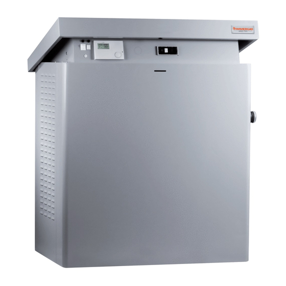
Page 9: Technical Characteristics And Dimensions
Technical characteristics and dimensions TECHNICAL - Total premix burner, modulating, with "metal foam" radiation combustion chamber. Premixing in the fan. Automatic separating CHARACTERISTICS AND backflow diaphragm from the combustion chamber. - Sound emissions at maximum power below 52 dBA for models 100- DIMENSIONS 350, 54 dBA for models 440-770 and 56 dBA for 900. -
Page 10: View Of Main Parts
Technical characteristics and dimensions VIEW OF MAIN PARTS Min. depth 100 mm Error Wiring Error Wiring N° Description N° Description code diagram code diagram HSCP CONTROL PANEL RETURN GLOBAL NTC GAS VALVE PROBE FLOW GLOBAL NTC BURNER COVER AUTOMATIC AIR BLEED VALVE E. -
Page 11: Dimensions
Technical characteristics and dimensions DIMENSIONS RIGHT SIDE VIEW FRONT VIEW (Supply condition for left side attachments) 62,5 TOP VIEW LEFT SIDE VIEW Flue outlets: Left side (supply condition) Right side Rear side ARES Tec Dimensions Unit Heating elements n° Height 1448 1448 1448... -
Page 12: Operating Data / General Characteristics
Technical characteristics and dimensions OPERATING DATA / GENERAL CHAR- ACTERISTICS ARES Tec ErP Boiler category 2H3P 2H3P 2H3P 2H3P 2H3P Modulation ratio 1 : 19,6 1 : 24,5 1 : 29,4 1 : 34,3 1 : 39,2 Nominal heat input on L.V.C. Qn Minimum heat input on L.C.V. -
Page 14: Instructions For Installation
Instructions for the installer INSTRUCTIONS FOR ATTENTION! In rooms with aggressive vapour or dust, the INSTALLATION appliance must operate independently of the air in the room of installation! GENERAL RECOMMENDATIONS ATTENTION! The appliance must be installed by an authorised ATTENTION! company possessing professional-technical This boiler must only be employed for its explicitly qualifications in accordance with the law, who, under... -
Page 15: Packaging
Instructions for the installer PACKAGING To take the boiler off of the pallet it is necessary to use a jib crane, to avoid damaging it. - Remove the casings and harness it using slings "A" fig. 3 being careful The ARES Tec ErP boiler is supplied assembled in a sturdy cardboard to pass the slings through the load bearing crossbeams of the frame box. -
Page 16: Operation To Unload And Remove The Packaging
Instructions for the installer OPERATION TO UNLOAD AND REMOVE THE PACKAGING ATTENTION! Handle using forklift or hoist and sling. ATTENTION! Sling slotting points for lifting. The slings must be assembled on the load bearing crossbeams. To take the boiler off of the pallet it is necessary to use a jib crane, to avoid damaging it. -
Page 17: Positioning The Heating Control Unit
Instructions for the installer POSITIONING THE HEATING The boiler can be placed on a flat platform that is sufficiently sturdy in size, in plan, no smaller than the boiler measurements and with a CONTROL UNIT minimum height of at least 100 mm so that the trap for condensate drainage can be installed. -
Page 18: Connecting The Boiler
Instructions for the installer CONNECTING THE BOILER Diaphragms and gaskets. Diaphragm installed on the first and last element of the flow manifold The ARES Tec boiler leaves the factory set up for Ø 18 (A), internal Ø 27 (B). the hydraulic (flow and return) and gas connections Gaskets installed on all of the other elements (C). -
Page 19: Gas Connection
Instructions for the installer GAS CONNECTION Before installation it is advisable to clean the inside of the fuel intake pipe thoroughly, in order to remove any residues that could stop the boiler from operating The gas intake pipe must be connected to the boiler using the respective smoothly. -
Page 20: System Flow And Return Pipe Connection
Instructions for the installer SYSTEM FLOW AND RETURN PIPE Make sure the pipes in the system are not used as earthing connections for the electrical or telephone CONNECTION system. They are absolutely not suitable for this purpose. Serious damage to pipes, boiler and radiators could The heating flow and return must be connected to the boiler by the occur in a short amount of time. -
Page 21: Additional Safety, Protection And Control Devices
120°C. generator output (flow pipe) at a distance of < 500 mm, and must not have a cut-off device installed on it. Not supplied by Immergas. 17 Inspection traps: approved for the inclusion of control devices. - Page 22 Instructions for the installer Recommended installation...
-
Page 23: Determining The Primary Circuit Pump Or Boiler Pump
The resistance curve on the water side of the boiler is represented in the table provided below. Immergas provides a series of primary rings complete with an accurately The pump is not an integral part of the boiler. sized pump, if alternative solutions are being used, the boiler pump... -
Page 24: Condensate Drain
Instructions for the installer 3.10 CONDENSATE DRAIN It is forbidden to drain the condensate towards rain pipes, given the risk of ice and degradation of materials normally used to build the rain pipes themselves. The condensate drain into the sewer must be: - built to avoid gaseous combustion products from leaking out into the The drain fitting must be visible. -
Page 25: Connecting The Flue
Instructions for the installer 3.11 CONNECTING THE FLUE Such as PVDF (polyvinyldimethylfluoride) or PPS (simple translucent polypropylene) or aluminium or other materials with the same features, in observance of regulation in force. Exhaust is discharged at very low temperatures (Max 84°C approx) in condensation boilers. -
Page 26: Electrical Connections
Instructions for the installer 3.13 ELECTRICAL CONNECTIONS able for the maximum power absorbed by the appliance, as stated on the plate, making sure in particular that the section of the system's cables is suitable for the power absorbed by the appliance. GENERAL RECOMMENDATIONS Electrical safety of the appliance is only ensured when it is correctly connected For the main power supply to the appliance, never use adapters, multiple sockets... - Page 27 Instructions for the installer Danger! Remember that it is necessary to install a bipolar Electrical installation must only be carried out by an switch on the electrical supply to the boiler with a authorised company. max distance between the contacts of 3 mm, easy to Before setting up the connections or any operation on access, so that maintenance operations can be carried the electrical parts, always cut-off the electrical supply...
- Page 28 Instructions for the installer NOTE: If other services (storage tanks, mixed zones, solar, etc.) are requested, it is The boiler is provided with set-up to manage one direct necessary to purchase SHC multifunction modules to connect to the local flow and one storage tank. bus for total temperature control management via HSCP (and UFLY).
-
Page 29: Connection Diagram
Instructions for the installer 3.14 CONNECTION DIAGRAM POWER SUPPLY, INAIL, MODULATION PUMP, EXTERNAL PROBE, FLOW SWITCH. SAFE 1.3 (T.S.) 1.1 (P. max.) 1.2 (P. min.) 230 V 50 Hz SUPPLIED IF-EXT. MIN 10-0V mod. 12 11 10 9 8 7 6 5 4 3 2 1 4 5 6 7 10 11 12 13 14 1 2 3 4 5 6... - Page 30 Instructions for the installer 2 ARES Tec connected in a set, managed by Cascade Manager. PRIMARY LOOP anello primario SAFE 1.3 (T.S.) 1.1 (P. max.) 1.2 (P. min.) 230 V 50 Hz IF-EXT. MIN 10-0V mod. 12 11 10 9 8 7 6 5 4 3 2 1 4 5 6 7 10 11 12 13 14 1 2 3 4 5 6...
- Page 31 Instructions for the installer Ares Tec connection 2 in battery controlled by Cascade Manager with Direct Zone plus Production of Domestic Hot Water. anello secondario SECONDARY LOOP Stemp. P. Car. 12 11 10 9 8 7 6 5 4 3 2 1 Note Nota: For installation with a single boiler, the above connec-...
- Page 32 Instructions for the installer Wilo Stratos modulating Pump setting (Enable ext 0 - 10 V input).
-
Page 33: Practical Connection Diagram
Instructions for the installer 3.15 PRACTICAL CONNECTION DIAGRAM al / to HSCP 1° Mod. alla / to (Y1) VM (A) alla / to GR eBUS+ PK eBUS- 1 MOD. (Y1) LTLG 1° Mod. F 6.3A 230 V 50 Hz SR R min. - Page 34 Instructions for the installer Last Module Intermediate VM (A) VM (A) BLUE BROWN BLACK GREEN GREY LIGHT BLUE ORANGE PINK FILTE R FILTE R YELLOW YELLOW / GREEN WHITE PURPLE VIOLA 2° - 8° Mod. Al / To conn. A4 scheda alim. / A4 power supply mod.
-
Page 35: System Filling And Emptying
2.2. This valve must never be used to empty the Immergas will not be held liable in case of damage system, since all of the dirt contained in the system may accumulate caused to people, animals or property due to failure in the boiler, jeopardising smooth operation. -
Page 36: Check The Adjustment Of The Pressure To The Burner
Instructions for the installer 3.18 CHECK THE ADJUSTMENT OF THE PRESSURE TO THE BURNER ATTENTION! All of the instructions below are provided for the exclusive use of authorised assistance personnel. All boilers leave the factory calibrated and approved, nevertheless, if the calibration conditions need to be changed it is necessary to re-calibrate the gas valve. - Page 37 Instructions for the installer A) Adjustment at maximum power. Follow this procedure to adjust the other modules as well. - Unscrew the closing cap for flue exhaust analysis point. - Place the analyser probe inside the flue analysis point. - Make burner 1 operate at max power, following the procedure If the measured flow rate is too low, make sure the supply and draining illustrated below in "chimney sweep function "...
- Page 38 ERRATA CORRIGE Instructions for the installer When replacing the gas valve or having difficulty with ignition: Screw general adjusting screw "A" on clockwise until it stops, then unscrew by 9 revolutions (methane). Check boiler ignition. If it does not start up unscrew screw "A"...
-
Page 39: Emergency And Safety Operations
Instructions for the installer 3.19 EMERGENCY AND SAFETY OPERATIONS NOTE: the devices are positioned under the casing The BCM board prevents the system from shutting down if management next to the control unit. of the HSCP system or main boiler system are out of service (see the BCM manual). -
Page 40: First Ignition
First ignition must be carried out by professionally The individual in charge of the system must be instructed in the use authorised company. Immergas will not be held and operation of the heating system, in particular: liable in case of damage caused to people, animals or - Supply the system manager with the "THE SYSTEM MANAGER'S... -
Page 41: Inspections And Maintenance
Inspections and maintenance INSPECTIONS AND Instructions for inspection and maintenance. MAINTENANCE Only original spare parts must be used to ensure a long life for all of the functions of your appliance, and to avoid changing the conditions of the approved INSTRUCTIONS FOR INSPECTION standard product. - Page 42 Inspections and maintenance We urge you to have authorised company fulfil requirements regarding periodic maintenance checks. Since dust is extracted from the inside, the resistance on the flue side, through the boiler, will increase, leading to a decrease in the heat load (and, consequentially, in the power).
- Page 43 Inspections and maintenance - Take out the red silicone pipes and then the fan chamber. Element screws. -- Unhook the fan chamber clamping spring (right/left side). - Take out screws "A" from each element (with 13mm socket and flat key).
- Page 44 Inspections and maintenance - Lift the burner block (front part). - Lift the rear burner block slightly and take out 2 pins with a 5 mm hex key, until you reach holes "C" (left and right side). - Take out the gas fittings from the gas manifold with a 36 mm flat key.
- Page 45 Inspections and maintenance Third phase - Reassembly. Second phase – Cleaning. - Once the body and/or burners have been cleaned, put the burners - Take out the gaskets and burners. back in their places. - Dry clean the burners using compressed air and operating from the - Put the new graphite gaskets in place.
-
Page 46: Programming The Operation Parameters
Inspections and maintenance PROGRAMMING THE OPERATION 3 - Device management SELECTION PARAMETERS ATTENTION! Function reserved exclusively to Authorised Service Centres. Select with knob ‘‘C’’ and press key ‘‘A’’ in order to access the tech- nical programming area of each device (you must enter password 0000). 1 - SELECTION 4 - SELECTION Use knob ‘‘C’’... -
Page 47: Bcm. Prameters
Inspections and maintenance BMM. PARAMETERS BMM parameters - ARES TEC 400 - 550 - 660 - 770 - 90 0 IMPOSTAZIONI CODICE SIMBOLO DESCRIZIONE PARAMETRO U.M. FABBRICA CH#1: Minimum Setpoint °C CH#1: Maximum Setpoint °C Pump Post-circulation min. Enabling: 2 = Boilers cascade 3 = Single boiler Central Heating only 4 = Single boiler + any storage tank kit Ignition Modulation... -
Page 48: Bcm. Prameters
Inspections and maintenance BCM. PARAMETERS BCM parameters - ARES TEC 440 - 550 - 660 - 770 - 900 Code Symb. Description Unit Factory settings Services Enabled Gen: Temp. Max Differential °K 50,0 Burner Hysteresis °K 20,0 CH#1: Minimum Setpoint °C 20,0 40,0... -
Page 49: Error Code
Error codes ERROR CODE When the boiler detects a fault, the alarm symbol is displayed on the It is possible to reset the boiler by pressing “A” from HSCP or RESET screen together with the relative error code and description. from BCM ( Num ) = see key Par. - Page 50 Error codes SPEED OUT OF CONTROL Check operation of the fan (18) and the connections Fan speed alteration; the speed is higher than what is requested. CLOGGED DRAINS Check Chimneys / Check Drain Trap. Stop WATER IN THE COMBUSTION CHAM- Check the combustion chamber / check the drain trap.
- Page 52 Immergas S.p.A. 42041 Brescello (RE) - Italy Tel. 0522.689011 Fax 0522.680617 Certified company ISO 9001...