Table of Contents
Advertisement
Quick Links
Advertisement
Table of Contents

Related Manuals for Teledyne Lecroy T3AWG3K Series


Summary of Contents for Teledyne Lecroy T3AWG3K Series
- Page 1 Operator’s Manual T3AWG3K Series Simple TrueArb Rev. 1.7...
-
Page 2: Table Of Contents
Summary GENERAL SAFETY SUMMARY ..........................4 ..........................4 VOID IRE OR ERSONAL NJURY Use Proper Power Cord ............................4 Ground the Product ............................... 4 Observe All Terminal Ratings ..........................4 Power Disconnect ..............................4 Do Not Operate Without Covers ........................... 4 Do Not Operate With Suspected Failures ...................... - Page 3 Analog Outputs ..............................18 Marker Output ..............................18 Trigger In ................................19 Soft keyboard and rotary knob ........................... 20 Numeric Keypad ..............................21 T3AWG3352/3252 ..........................22 ANEL T3AWG3354/T3AWG3254 – R T3AWG3358/T3AWG3258 ............. 23 ANEL ANEL External Modulation Input Connector ......................... 24 Reference Clock Input Connector ........................
-
Page 4: General Safety Summary
EMC C ............................... 72 OMPLIANCE ..............................72 AFETY OMPLIANCE ............................73 NVIRONMENTAL OMPLIANCE General Safety Summary Review the following safety precautions to avoid injury and prevent damage to this product or any products connected to it. To avoid potential hazards, use this product only as specified. Only qualified personnel should perform service procedures. -
Page 5: Safety Requirements
Operator’s Manual Simple TrueArb Application Safety Requirements This section contains information and warnings that must be observed to keep the instrument operating in a correct and safe condition. You are required to follow generally accepted safety procedures in addition to the safety precautions specified in this section. Safety Symbols Where the following symbols appear on the instrument’s front or rear panels, or in this manual, they alert you to important safety considerations. - Page 6 Operator’s Manual Simple TrueArb Application CAUTION The CAUTION sign indicates a potential hazard. It calls attention to a procedure, practice or condition which, if not followed, could possibly cause damage to equipment. If a CAUTION is indicated, do not proceed until its conditions are fully understood and met. WARNING The WARNING sign indicates a potential hazard.
-
Page 7: Environmental Considerations
Package Contents The standard T3AWG3K Series package includes the following: • T3AWG325X or T3AWG335X Arbitrary Waveform Generator equipment •... -
Page 8: Recommended Accessories
Operator’s Manual Simple TrueArb Application • Quick Start Guide • CE certificate Recommended Accessories T3AWG3352/3252 Item Description T3AWG3-8DIG/T3AWG3-8DIG-UPGRADE 8 Bit digital outputs (requires LVDS cable) T3AWG3-8DIG-TTL LVDS to LVTTL digital adapter probe T3AWG3-8DIG-SMA LVDS to SMA digital adapter cable T3AWG3-8DIG-MSCAB Digital output LVDS cable T3AWG3-RACKMOUNT Rack Mount Kit... -
Page 9: Key Features
Operator’s Manual Simple TrueArb Application Overall Dimensions Height: 143 mm Width: 362 mm Depth: 258 mm Model T3AWG3354-T3AWG3254 Net Weight 6.5kg Net Weight with Package 7 kg Overall Dimensions Height: 160 mm Width: 450 mm Depth: 340 mm Model T3AWG3358-T3AWG3258 Net Weight 10.8kg Net Weight with Package... -
Page 10: Installing You Instrument
Operator’s Manual Simple TrueArb Application • T3AWG3352/3252 Mixed signal generation: 2 analog output + 8 digital outputs (with T3AWG3- 8DIG option) • T3AWG3354/3254 Mixed signal generation: 4 analog output + 16 digital outputs (with T3AWG3- 16DIG-4CH option) • T3AWG3358/3258 Mixed signal generation: 8 analog output + 32 digital outputs (with T3AWG3- 32DIG-8CH option) •... -
Page 11: Environmental Requirements
Operator’s Manual Simple TrueArb Application Environmental requirements Before using this product, ensure that its operating environment is maintained within these parameters: Temperature Operating +5 °C to +40 °C (+41 °F to 104 °F) Non-operating -20 °C to +60 °C (-4 °F to 140 °F) Humidity Operating 5% to 80% relative humidity with a maximum wet bulk temperature of 29 °C at or below +40 °C, non-condensing. -
Page 12: Calibration
Operator’s Manual Simple TrueArb Application • Remove loose dust on the outside the instrument with a lint-free cloth. Use care to avoid scratching the front panel display. • Use a soft cloth dampened with water to clean the instrument. Use a 75% isopropyl alcohol solution as a cleaner. -
Page 13: Protect Your Instrument From Misuse
CAUTION. Do not apply excessive inputs over ±15 Vpk to Trigger Input connector. The instrument may be damaged. Obtaining the Latest Version Releases The latest release of the software may not be installed on your instrument. The latest version could be found on Teledyne LeCroy website (www.teledynelecroy.com) in the support area Install Simple TrueArb Application... - Page 14 If your instrument has already installed another version of the Simple TrueArb application, DO NOT uninstall it otherwise you will loose all the configurations and projects. 1. Download the Simple TrueArb setup package from Teledyne Lecroy website and decompress it to instrument’s local disk.
- Page 15 Operator’s Manual Simple TrueArb Application...
-
Page 16: Instrument Overview
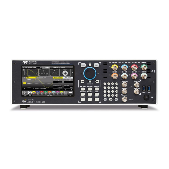
Operator’s Manual Simple TrueArb Application Instrument Overview Front Panel T3AWG3352/3252 Single ended analog outputs Trigger In and Power on/off Marker Output 7” Capacitive Numeric button Soft Keyboard and Touch Screen Keypad Rotary Knob... -
Page 17: Front Panel T3Awg3354/3254
Operator’s Manual Simple TrueArb Application Front Panel T3AWG3354/3254 Single ended analog outputs 2 USB 3.0 Numeric Trigger In 7” Capacitive ports Soft Keyboard and Keypad Touch Screen Rotary Knob Marker Output... -
Page 18: Front Panel T3Awg3358/3258
Operator’s Manual Simple TrueArb Application Front Panel T3AWG3358/3258 Single ended analog outputs 2 USB 3.0 Numeric Trigger In 7” Capacitive ports Soft Keyboard and Keypad Touch Screen Rotary Knob Marker Output The Touch screen functionalities and features are described in the Simple TrueArb Application paragraph. -
Page 19: Trigger In
Operator’s Manual Simple TrueArb Application Marker Out Specification Value Connector 1 BNC for each pair of channels on the Front Panel 50 Ω Output impedance Output level (into 50 Ω) 1 V to 2.5 V Important Note: the Marker Out 1 is linked to the Channel 1 and Channel 2, the Marker Out 2 is linked to the Channel Out 3 and Channel Out 4, the Marker Out 3 is linked to the Channel Out 5 and Channel Out 6, the Marker Out 4 is linked to the Channel Out 7 and Channel Out 8. -
Page 20: Soft Keyboard And Rotary Knob
Operator’s Manual Simple TrueArb Application Soft keyboard and rotary knob Most of the buttons you use with Simple TrueArb application are virtual ones on the touchscreen, but a few physical buttons control basic functions, such as the setting of amplitude, offset, frequency, etc. A physical numeric keypad is available on the front-panel and it can be used instead of the virtual numeric pad. -
Page 21: Numeric Keypad
Operator’s Manual Simple TrueArb Application Button Description HOME If you are in a sub-menu page, use this button to return to the main page. TRIGGER Use this button to send an internal trigger to the instrument. If the button is on and green the Use this button to start and stop the signal generation. -
Page 22: Rear Panel T3Awg3352/3252
Operator’s Manual Simple TrueArb Application When you select a parameter on the user interface, if you press a Unit Measure Range button it will automatically update the available range allowed for that parameter. Unit Measure Range Button Unit Measure Range Tera / pico Giga / nano Mega / micro... -
Page 23: Rear Panel T3Awg3354/T3Awg3254 - Rear Panel T3Awg3358/T3Awg3258
Operator’s Manual Simple TrueArb Application Rear Panel T3AWG3354/T3AWG3254 and Rear Panel T3AWG3358/T3AWG3258 • 2 slots for Removable SSD Digital Output Connectors: Pod D, Pod C, Pod B, Pod A (T3AWG3358/3258) Pod B, Pod A (T3AWG3354/3254) • 4 USB 3.0 ports •... -
Page 24: External Modulation Input Connector
Operator’s Manual Simple TrueArb Application External Modulation Input Connector Important Note: this connector is not used by TrueArb application. Reference Clock Input Connector The T3AWG-3K can use an external clock source to generate the sampling clock frequency. This feature allows to synchronize the generator with an external clock. The connector type is a SMA. -
Page 25: Sync In / Sync Out Connectors
Operator’s Manual Simple TrueArb Application Digital Connector on Two Channels model Sync In / Sync Out Connectors The purpose of those connectors is to connect and synchronize together multiple instruments: up to 4 instruments can be linked together. Those connectors are available on T3AWG3358/T3AWG3258 models only. -
Page 26: Quick Start Guide
Operator’s Manual Simple TrueArb Application Quick Start Guide If you are a beginner user, you can follow the steps here below to generate your first waveform. 1. Connect the power cord and the push the front-panel on/off switch to turn on the instrument. - Page 27 Operator’s Manual Simple TrueArb Application 7. Touch again the setting button to close the instrument settings window 8. By default the CH1, CH2 are disabled: it means that the outputs are mechanically disconnected from the load and the digital outputs are in OFF state. 9.
- Page 28 Operator’s Manual Simple TrueArb Application 11. Swipe down to switch from Channel 1 to Channel 2. In the Channel 2 by default the two sequencer entries will be two Sine Waveforms. 12. Enable the output channels by pressing the CH1 and CH2 buttons located in the bottom of the application so that they are no more grayed out.
- Page 29 Operator’s Manual Simple TrueArb Application 13. Touch the Entry 1 and set the Repetition[N]=2 than touch the Entry 2 and set Repetition[N]=3. 14. You can change the Amplitude/Voltage High and Offset/Voltage Low for each entry. 15. Press the RUN/STOP button and check the generated waveforms on the oscilloscope: the Entry 1 should be repeated two times and the Entry 2 should be repeated three times.
-
Page 30: Simple Truearb Application
Operator’s Manual Simple TrueArb Application Simple TrueArb Application The T3AWG-3K includes a 7” capacitive touch screen and Simple touch user interface based on a Microsoft Windows 10 platform. You can control instrument operations using one or all of the following entering methods: •... - Page 31 Operator’s Manual Simple TrueArb Application It is sometimes necessary to create long waveform files to fully implement a DUT test. In case where portions of a waveforms must be repeated, the waveform sequencer functionalities can save you a lot of memory-intensive waveform programming.
-
Page 32: User Interface Description
Operator’s Manual Simple TrueArb Application User Interface Description The Simple TrueArb software environment provides an easy access to all instrument features and parameters. Sequencer Toolbar Sequencer Area Waveform Area Command Bar The TrueArb user interface consists of four main elements: •... -
Page 33: Sequencer Area
Operator’s Manual Simple TrueArb Application As mentioned, the display is 7” capacitive touch screen display and you can use the gestures like in a mobile phone: If you use the Swipe up or down gesture on the Waveform Area you can switch between the Output Channel 1, Output Channel 2, …, Output Channel N page. - Page 34 Operator’s Manual Simple TrueArb Application Important Note: if you need to modify the waveform of the other channel that by default are automatically set to sine waveform when you add a new entry in the sequencer, you should use the swipe up/down gesture on the Graph Area or press the up/down arrow on the left side of the graph to change the Output Channel page.
-
Page 35: Sequencer Area Items
Operator’s Manual Simple TrueArb Application Sequencer area items • Memory Usage. Shows the percentage of memory used to store the waveforms placed in the sequencer Selection Button • Sequencer Entry. Each sequencer item contains several information: ➢ The index of the Entry (Entry N). Each entry is enumerated starting from 1 up to 16384. ➢... -
Page 36: Sequencer Toolbar
Operator’s Manual Simple TrueArb Application Sequencer Toolbar This sequencer toolbar contains several buttons to navigate and control the sequencer that are described here below in detail: Sequencer Toolbar Description First Entry Button – Press this button to go to the first entry. Last Entry Button –... -
Page 37: Waveform Area
Operator’s Manual Simple TrueArb Application Waveform Area This area is divided in two main sections, the Waveform Graph area that contains a graphical representation of the channel waveform and the Waveform Parameters area. The Waveform Graph gives a description of the waveform assigned to the current channel and sequencer entry. - Page 38 Operator’s Manual Simple TrueArb Application Waveform Vertical Parameters Entry Parameters Amplitude[Vpp] parameter It defines the difference between the maximum value and the minimum value of the waveform expressed in Volts. Offset[V] It defines the voltage of (Vmax+Vmin)/2 expressed in Volts where Vmax is the maximum level of the waveform and Vmin is the minimum level of the waveform Voltage High[V] It defines the maximum level of the waveform expressed in Volts...
- Page 39 Operator’s Manual Simple TrueArb Application IMPORTANT NOTES • The maximum value of repetitions is infinite: Repetitions[N]=Infinite • Entry Length[N]=2048 is the length of the selected sequencer entry • The minimum entry length is 32 samples. The entry length granularity is : o 1 if the entry length is >...
- Page 40 Operator’s Manual Simple TrueArb Application Below there is a description of the keypad items: 1. Parameter Name and Value: This area of the virtual keyboard displays the parameter name, value and unit of measure. 2. Numeric Keypad: this area contains the keys to edit the number that will be displayed in the area 1.
- Page 41 Operator’s Manual Simple TrueArb Application “Bksp” (backspace) button is provided for deleting erroneous key presses, “Delete” button deletes all digit of the textbox. 7. The horizontal scrollbar allows to change quickly the selected value. The position specifies the value between the allowed minimum and the maximum. The increment/decrement value entered by the rotary knob or by the scrollbar are applied to the instrument on the fly.
-
Page 42: Status Toolbar
Operator’s Manual Simple TrueArb Application Status Toolbar Trigger Information indicator: provides information on the trigger signal condition. o The Trigger status led notifies you that the instrument has received a trigger signal o The Waiting Trigger led notifies you when the instrument is waiting for a trigger signal. o The Trigger too fast led notifies you that the trigger event has been latched, but the trigger frequency is too high and the instrument cannot be rearmed before the completion of the previous trigger event. - Page 43 Operator’s Manual Simple TrueArb Application Settings Button – Use this button to open the output channel Settings, device Settings, Marker Settings and Sequencer Settings. (For more information, please refer to the relative section). Wavef. List – Use this button to open a page where you can Import/Export a waveform from file.
- Page 44 Operator’s Manual Simple TrueArb Application More Button Menu Items Description Exit Button – Press this button to close the application. Full/Float Button – press this button to maximize or reduce the application screen; in this way you can access to Windows OS. Load From Button –...
-
Page 45: Settings
Operator’s Manual Simple TrueArb Application Waveform Editor – Use this button to open the Waveform Editor software. (For more information please refer to the Waveform Editor User Manual). License button – Use this button to enter the License setup page. (For more information, please refer to the relative section). - Page 46 Operator’s Manual Simple TrueArb Application ∞ • Single/Burst: when the RUN/STOP button is pressed the instrument waits for a trigger event. When the trigger event occurs each waveform will loop as written in the entry repetition parameter and the entire sequence will be repeated circularly many times as written in the Burst Count[N] parameter.
- Page 47 Operator’s Manual Simple TrueArb Application Start Trigger ∞ • Stepped: after pressing the RUN/STOP button each entry waits for a trigger event before its execution. The waveform of the entry will loop as written in the entry repetition parameter. After the generation of an entry has completed, the last sample of the current entry or the first sample of the next entry is held until the next trigger is received.
- Page 48 Operator’s Manual Simple TrueArb Application Resampling Strategy It defines the strategy to adapt the original waveform length to the sequencer entry length. The “Sample increasing strategy” parameter defines the strategy used to adapt the waveform length to the sequencer entry length in the case where the original waveform length is shorter than the sequencer entry length.
- Page 49 Operator’s Manual Simple TrueArb Application If External is selected, the sampling clock is synthesized using the clock provided externally to the Ref.Clock In SMA connector. When the External is selected, the Reference Clock[Hz] control will appear and the user needs to specify the Reference Clock frequency[Hz].
-
Page 50: Channel Settings
Operator’s Manual Simple TrueArb Application opposite. “Both Edges” means that Trigger is sensitive to both edges of the signals. It has effect only when the selected Source is External. Threshold [V] It is the threshold that the external signal applied to the “TRIGGER IN” connector must cross to issue a Trigger event to the instrument. - Page 51 Operator’s Manual Simple TrueArb Application as the maximum time skew allowed. The edited value is automatically rounded to the closest value that the hardware can implement. • Output Impedance: defines the output impedance of the analog outputs. It can be set 50 Ohm or Low Impedance (5 Ohm).
- Page 52 Operator’s Manual Simple TrueArb Application • Digital Channels: it is possible to enable up to 8 digital line on two channels model, up to 16 on four channels model and up to 32 on eight channels model. If the Digital Channels number is 0, the DIG button will be disabled.
- Page 53 Operator’s Manual Simple TrueArb Application 12 bits 12 bits 12 bits 14 bits 16 bits 16 bits 16 bits 16 bits 12 bits 12 bits 12 bits 12 bits 16 bits 16 bits 16 bits 16 bits 12 bits 12 bits 12 bits 12 bits 14 bits...
-
Page 54: Marker Settings
Operator’s Manual Simple TrueArb Application Marker Settings On the marker output page you can set the behaviour and parameters of the Marker signal that is provided at the front panel MARKER OUT BNC connector. On four and eight channels model, press the marker button to change the selection of the Marker signal. The available Marker signals depend on the instrument Model, refer to the Marker Output section for a complete description. -
Page 55: Sequencer Settings
Operator’s Manual Simple TrueArb Application Marker Mode: • Automatic: the marker has a behavior that depends on the Run Mode. In detail: o Continuous: the instrument generates a Marker pulse of the duration from 6ns to 12 ns (depending on the sampling frequency), synchronous with the analog outputs, for each sequencer entry and for each repetition. - Page 56 Operator’s Manual Simple TrueArb Application Sequencer item Length Strategy: • Adapt to the longer analog waveform: if this option is selected the length of an entry of the sequencer by default will be equal to the length of the longer channel waveform, among all analog channels, assigned to the entry.
-
Page 57: Waveform List
Operator’s Manual Simple TrueArb Application Waveform List Press the button to open the Waveform List page that collects all the waveforms available in the current configuration. The T3AWG-3K series contains by default a set of Factory Predefined Waveforms that are common to all configurations. - Page 58 Operator’s Manual Simple TrueArb Application How to import an Analog/Digital waveform from a file Import button allow you to import data from a file to create a new waveform The supported file formats are: • TXT – New line (\n) separated text file (one column only with no header) •...
- Page 59 Operator’s Manual Simple TrueArb Application How to export an Analog/Digital waveform to a file • Select an analog or digital waveform on the waveform list • Press the button • The exported waveform will be stored in a proprietary binary .zip file format that can be shared with other instruments running the same application.
-
Page 60: Configurations
Operator’s Manual Simple TrueArb Application Configurations A configuration contains the data in proprietary format relative to the channel waveforms inserted into the sequencer and all the instrument and sequencer parameters. Save As... A configuration can be saved by means of the “Save As”... -
Page 61: Load From
Operator’s Manual Simple TrueArb Application Load From… Touching the “Load From” button in the “More” menu, a page will be opened that shows the list of all the saved and imported configurations. If you select an existing Configuration, you will load all the settings into the instrument. In the “Load From”... -
Page 62: Remote Desktop Connection
Operator’s Manual Simple TrueArb Application In the top of the page the Host Name and the IP Address of the instrument are shown. The slider on the right side of the page allows to enable or disable the SCPI server. By default it is enabled. Remote Desktop Connection If you need to connect to the instrument using the remote desktop connection, you should insert the following credentials:... -
Page 63: Calibration And Diagnostic
Operator’s Manual Simple TrueArb Application Calibration and Diagnostic The calibration button in the More.. menu opens the Calibration and Diagnostic page. Below a description of the actions executed by pressing the buttons located in the page: • Warm up button: touching this button will start the warm up instrument procedure that will take 30 minutes. -
Page 64: License
Operator’s Manual Simple TrueArb Application License The license button in the More.. menu opens the License page that serves to manage the license options. Touching the Add New License button it is possible enter a new licence key to enable any of the following licences: T3AWG-3352/3252 models a. - Page 65 Operator’s Manual Simple TrueArb Application T3AWG-3354/3254 models a. T3AWG3-XL-4CH: 1024 Mpt/Ch Memory Option for T3AWG3K-4CH b. T3AWG-XL-UPGRADE-4CH: 1024 Mpt/Ch Memory Upgrade-4CH c. T3AWG3-HV-4CH: High Voltage (12 Vpp on 50 Ohm) for T3AWG3K-4CH d. T3AWG3-HV-UPGRADE-4CH: High Voltage (12 Vpp on 50 Ohm) UPGRADE for T3AWG- e.
-
Page 66: Appendix A - Digital Option And Accessories
Operator’s Manual Simple TrueArb Application Appendix A – Digital Option and accessories When you buy the digital option, you will receive a software licence key and 1 mini-SAS HD cable 1m long. Be careful that even if this cable has the same mechanical dimension of SFF-8644 standard the electrical connection are customized, so it's not possible to use standard mini-SAS HD cables otherwise the unit will be damaged. - Page 67 Operator’s Manual Simple TrueArb Application Mini-SAS HD connector pinout Mini-SAS HD connector Assigned signal T3AWG3-8DIG-SMA Mini SAS HD to 16 SMA cable (8 LVDS output) +12Vcc +12Vcc SMA Ground DO7_P DO 7_P DO7_N DO 7_P DO0_P DO 0_P DO0_N DO 0_N SMA Ground CS1 (RESERVED).
- Page 68 Operator’s Manual Simple TrueArb Application SMA Ground DO1_P DO 1_P DO1_N DO 1_N SMA Ground +5Vcc +5Vcc SMA Ground D5_P DO 5_P D5_N DO 5_N SMA Ground D2_P DO 2_P D2_N DO 2_N SMA Ground SCL (RESERVED). Do not connect. SDA (RESERVED).
-
Page 69: 1.1 T3Awg3-8Dig-Sma
Operator’s Manual Simple TrueArb Application 1.1 T3AWG3-8DIG-SMA The T3AWG3-8DIG-SMA cable adapter converts from the Mini SAS HD connector located on the rear of the instrument to 16 SMA connectors. This cable ensures the best signal integrity and flexibility required for transmitting the high speed digital signals provided by the T3AWG-3K generator series. Output connector Output type LVDS... -
Page 70: 1.2 B. T3Awg3-8Dig-Ttl
Operator’s Manual Simple TrueArb Application 1.2 B. T3AWG3-8DIG-TTL The T3AWG3-8DIG-TTL is a 8 bit LVDS to LVTTL converter that converts LVDS differential signals provided by the mini-SAS HD digital connector to standard LVTTL single ended signals. The probe provides the possibility to programme by software the voltage high level of the TTL signals from 0.8V to 3.8V. - Page 71 Operator’s Manual Simple TrueArb Application Below the description of the TTL signal connector is provided. Output connector 20 position 2.54 mm 2 Row IDC Header Output electrical standard LVTTL Output impedance 50 Ω nominal Output voltage 0.8V to 3.8V programmable (same for all channels) Maximum Update Rate 125 Mbps @ 0.8V and 400 Mbps @ 3.6V Dimensions...
-
Page 72: Certifications
Operator’s Manual Simple TrueArb Application Certifications Teledyne LeCroy certifies compliance to the following standards as of the time of publication. Please see the EC Declaration of Conformity document shipped with your product for current certifications. EMC Compliance EC DECLARATION OF CONFORMITY - EMC The instrument meets intent of EC Directive 2014/30/EU for Electromagnetic Compatibility. - Page 73 The instrument is subject to disposal and recycling regulations that vary by country and region. Many countries prohibit the disposal of waste electronic equipment in standard waste receptacles. For more information about proper disposal and recycling of your Teledyne LeCroy product, please visit teledynelecroy.com/recycle.