Table of Contents
Advertisement
Generators
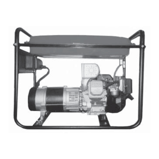
GENERATOR – MANUAL START
11 HP – 6,000 W
Model 54206
OPERATING INSTRUCTIONS
®
3491 Mission Oaks Blvd., Camarillo, CA 93011
Visit our Web site at: http://www.harborfreight.com
®
Copyright
2002 by Harbor Freight Tools
. All rights reserved. No portion of this
manual or any artwork contained herein may be reproduced in any shape or form
without the express written consent of Harbor Freight Tools.
For technical questions, please call 1-800-444-3353.
Advertisement
Table of Contents

Related Manuals for Chicago Electric 54206


Summary of Contents for Chicago Electric 54206
- Page 1 Generators GENERATOR – MANUAL START 11 HP – 6,000 W Model 54206 OPERATING INSTRUCTIONS ® 3491 Mission Oaks Blvd., Camarillo, CA 93011 Visit our Web site at: http://www.harborfreight.com ® Copyright 2002 by Harbor Freight Tools . All rights reserved. No portion of this manual or any artwork contained herein may be reproduced in any shape or form without the express written consent of Harbor Freight Tools.
-
Page 2: Product Specifications
STORE IDLE EQUIPMENT. When not in use, tools and equipment should be stored in a dry location to inhibit rust. Always lock up tools and equipment, and keep out of reach of children. SKU 54206 PAGE 2 REV 12/02 REV 12/03... - Page 3 WARNING: The warnings, precautions, and instructions discussed in this manual cannot cover all possible conditions and situations that may occur. The operator must understand that common sense and caution are factors, which cannot be built into this product, but must be supplied by the operator. SKU 54206 PAGE 3...
- Page 4 The supporting floor/ground surface should be level, and strong enough to safely hold the weight of the Generator. If the floor/ground surface is not level, strong cross members should be placed under the full length of the Generator Frame (part #21) at its low side. SKU 54206 PAGE 4...
- Page 5 Mechanical Precautions: ALWAYS turn off the Engine when not in use or when performing maintenance. Allow the Engine to completely cool, and disconnect the Engine’s Spark Plug Cable from the Spark Plug before carrying out maintenance. SKU 54206 PAGE 5...
- Page 6 Noise Precautions: Prolonged exposure to noise levels above 85 dBA is hazardous to hearing. Always wear ANSI approved ear protection when operating or working around the Generator when it is running. SKU 54206 PAGE 6...
- Page 7 8.1 - 12 12.1 - 15 15.1 - 20 FIGURE A REQUIRED MINIMUM EXTENSION CORD GAUGE – 240 VOLT NAMEPLATE EXTENSION CORD LENGTH _______________________________________________ AMPERES (At Full Load) 0-25 Feet 25-50 Feet 50-100 Feet 100-150 Feet FIGURE B SKU 54206 PAGE 7...
-
Page 8: Installation
Use care and the proper lifting or hoisting equip- ment, if required, when moving it to the installation location. Always connect hoist lines to the Frame (part #21) of the Generator. SKU 54206 PAGE 8 REV 12/02... -
Page 9: General Location
The grounding rod must be an earth-driven copper or brass rod (electrode) which can adequately ground the Generator. Refer to Article 250 of the National Electrical Code. (See Figure C, next page.) SKU 54206 PAGE 9... - Page 10 Check the Fuel Gauge (part #34) for the amount of unleaded gasoline in the Fuel Tank (part #32). If necessary, remove the Fuel Tank Cap (part #37) and refill the Fuel Tank with unleaded gasoline. Then, replace the Fuel Tank Cap. (See Figure F, page 12.) SKU 54206 PAGE 10...
- Page 11 FRAME FUEL VALVE (#21) (#31) “ON/OFF” FUEL SWITCH CHOKE STARTER PULLEY FIGURE D FUEL TANK (#32) OIL FILL CAP ENGINE CRANKCASE FIGURE E SKU 54206 PAGE 11...
- Page 12 Turn the Fuel Valve (part #31) to its vertical “OPEN” position. (See Figures D and G.) Move the Engine’s Fuel Choke all the way to the right to its “START” position. (See Figures D and G.) FUEL VALVE (#31) FUEL CHOKE START FIGURE G SKU 54206 PAGE 12...
- Page 13 Breaker(s). Restart the Generator, if necessary, and continue powering the remaining tools and equipment. (See Figure H.) AC CIRCUIT OVERLOAD BREAKER (#40) 240 VAC TWIST LOCK OUTLET (#42) 120 VAC OUTLET (#41) FIGURE H SKU 54206 PAGE 13 REV 12/02...
-
Page 14: Inspection, Maintenance, And Cleaning
UNDERTAKEN BY CERTIFIED AND LICENSED TECHNICIANS, AND NOT BY THE BUYER. THE BUYER ASSUMES ALL RISK AND LIABILITY ARISING OUT OF HIS OR HER REPAIRS TO THE ORIGINAL PRODUCT OR REPLACEMENT PARTS THERETO, OR ARISING OUT OF HIS OR HER INSTALLATION OF REPLACEMENT PARTS THERETO. SKU 54206 PAGE 14... -
Page 15: Parts List
Bolt (M5 x 12) Outlet (120 V/15A) Panel Outlet (240V/20A) Frame Wing Nut Shock Absorber Support ASSEMBLY DIAGRAM NOTE: Some parts are listed and shown for illustration purposes only, and are not available individually as replacement parts. SKU 54206 PAGE 15...