Advertisement
Quick Links
StorEdge™ Wiring Guide & On Site Checklist for North America
Revision History
Version 1.4 (November 2018)
Added support of LG Chem batteries with the disconnect switch.
Added battery self-test.
Version 1.3 – support for connection of 2 LG batteries
Version 1.2 – menu and checklist updates
Version 1.1 – support for LG batteries
Version 1.0 – initial version, using Tesla batteries
This document is a battery wiring guide and contains an on-site checklist with steps for post-installation verification of a StorEdge system, for the following batteries:
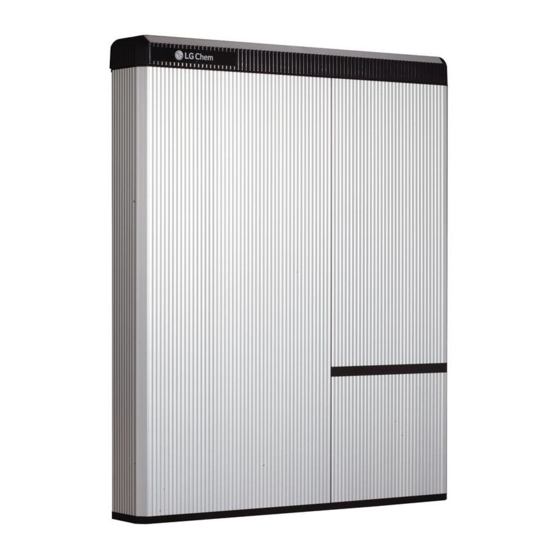
LG Chem RESU10H
CAUTION
For proper battery performance, the LG Chem battery should remain connected to the StorEdge Inverter and in charging mode. Extended battery
disconnection may result in deep discharge and damage the battery.
For more details, refer to the StorEdge Installation Guide supplied with the StorEdge Inverter. For additional assistance contact SolarEdge Support
Support and Contact Information
(refer to the section
on page 13).
Advertisement

Summary of Contents for SolarEdge StorEdge LG Chem RESU10H
- Page 1 For proper battery performance, the LG Chem battery should remain connected to the StorEdge Inverter and in charging mode. Extended battery disconnection may result in deep discharge and damage the battery. For more details, refer to the StorEdge Installation Guide supplied with the StorEdge Inverter. For additional assistance contact SolarEdge Support Support and Contact Information (refer to the section on page 13).
-
Page 2: Wiring Guide
Wiring Guide WARNING! The LG Chem battery must be powered off before wiring. LG Chem batteries are available with either of the following two types of powering mechanism design: With the disconnect switch (requires Firmware version 3.24xx or later) With the auxiliary power switch Figure 1: LG Chem Disconnect/Auxiliary Power Switch and Circuit Breaker To power off the battery: Turn off the circuit breaker. - Page 3 Wiring Types and Connectors To connect the battery to the StorEdge Inverter, use the following wiring types and connectors: Recommended Cable Type (min-max cross section) SolarEdge Connector LG Chem RESU10H Battery Connector DC: 10 AWG (14-10 AWG), 600V insulated BAT DC +...
- Page 4 B- <> B- and A+ <> A+ on the same twisted pair Figure 2: Connecting an LG Chem RESU10H Battery to a StorEdge Inverter with Two DIP Switches and SolarEdge Meter Connecting an LG Chem RESU10H Battery to a StorEdge Inverter with Three DIP Switches and SolarEdge Meter...
- Page 5 Wiring Diagrams – Connecting Two LG Batteries 12-10 AWG 600V insulated Junction Box ENABLE_H 24 AWG 600V EN_GND RS485_H and RS485_L on the same twisted pair Figure 4: Connecting Two LG Chem RESU10H Batteries...
- Page 6 Wiring Diagrams – Auto-transformer Connection Figure 5: Connecting the Auto-transformer to the Inverter...
-
Page 7: Switch Settings
Switch Settings Setting the DIP Switches on the Inverter Communication Board Set DIP switch SW7 RS485-1 RS485-2 For RS485-1 connections, use DIP Switch 1 (leftmost): For RS485-2 connections, use DIP Switch 2 (rightmost): * ON (up): Terminated (no meter installed) * ON (up): Terminated (no meter installed) * OFF (down): Not terminated (meter is installed) * OFF (down): Not terminated (meter is installed) - Page 8 Follow the checklist below to verify that the system is properly connected and configured. The checklist is suitable for a backup system with a single StorEdge Inverter, a single battery, an Auto-transformer and a single SolarEdge Electricity Meter installed at the grid connection point. For other system configurations, follow the steps in the StorEdge Installation Guide supplied with the StorEdge Inverter.
- Page 9 Remove the activation card from the inverter. 2.11 Download the latest firmware version available at: https://www.solaredge.com/storedge/firmware to a microSD card. 2.12 Insert the microSD card with the upgrade file to the designated slot located on the inverter communication board.
- Page 10 For a system with multiple inverters that has a single RS485 bus only, install and configure an RS485 Expansion Kit. Refer to the RS485 Expansion Kit Installation Guide. http://www.solaredge.com/files/pdfs/RS485_expansion_kit_installation_guide.pdf RS485 Connection Verification Press the inverter external LCD light button to display the status screens one after the other until a screen like the following is displayed:...
- Page 11 Check the RS485 communication status: Verify that the number under Prot displays the number of configured devices. Verify that the number under ## displays the number of communicating devices. Check the meter(s): In the meter(s) status screen check that the status is OK. If Comm. Error appears, refer to the troubleshooting section in the supplied installation guide.
- Page 12 Enter Setup mode and select Maintenance → StorEdge Self-Test → Start Test. The battery charges and discharges within approximately two minutes to check performance. During the test, the following message is displayed: Upon the test completion, the following message is displayed: ...
-
Page 13: Support And Contact Information
Turn the AC power to the inverter ON, and verify that the inverter is operating properly. Support and Contact Information If you have technical queries concerning our products, please contact us: USA and Canada: +1 510 498 3200 Worldwide: +972 073 2403118 Fax: +1 (530) 273-2769 Email: support@solaredge.us...