
Related Manuals for Vaisala HMD60 Series


Summary of Contents for Vaisala HMD60 Series
- Page 1 M212243EN-A User Guide HMD60 Series Humidity and Temperature Transmitters for Ducts in HVAC HMD65...
- Page 2 English versions are This product contains software developed applicable, not the translations. by Vaisala or third parties. Use of the The contents of this document are subject software is governed by license terms and to change without prior notice.
-
Page 3: Table Of Contents
Documentation Conventions................3 Trademarks......................4 Product Overview................... 5 Introduction to HMD60 Series.................5 HMD65 Basic Features and Options............... 5 Available Parameters and Default Scaling............. 5 Connectivity to Vaisala Insight Software............6 Transmitter Parts....................7 2.5.1 Cable Gland and Conduit Options............8 2.5.2 Filter Options....................8 2.5.3... - Page 4 HMD65 User Guide M212243EN-A Connecting HMD60 to MI70 Indicator............31 Basic Display....................32 Graphical Display.................... 32 Main Menu....................... 32 Holding and Saving the Display..............33 Recording Data....................33 Calibration and Adjustment..............34 Calibration and Adjustment Overview............34 Calibration and Adjustment Using Trimmers..........34 7.2.1 1-Point Adjustment Using Trimmers and Reference Calibrator..
-
Page 5: About This Document
Chapter 1 – About This Document 1. About This Document 1.1 Version Information Table 1 Document versions Document Code Date Description M212243EN-A April 2019 This manual. First version of the document. 1.2 Related Manuals Table 2 Related Manuals Document Code Description M212264EN HMD65 Multilingual Quick Guide M212016EN HMD62 and TMD62 User Guide M212049EN... -
Page 6: Trademarks
HMD65 User Guide M212243EN-A 1.4 Trademarks Vaisalaâ and HUMICAPâ are registered trademarks of Vaisala Oyj. Windowsâ is either a registered trademark or trademark of Microsoft Corporation in the United States and other countries. All other product or company names that may be mentioned in this publication are trade... -
Page 7: Product Overview
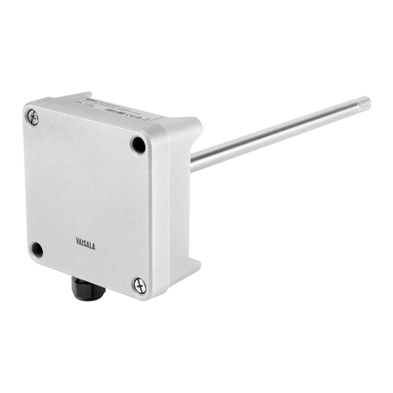
The duct mounted HMD60 HUMICAPâ Humidity and Temperature Transmitters are designed for monitoring humidity and temperature in demanding HVAC and light industrial applications. HMD60 series transmitters provide stable, reliable, and highly accurate (up to ±1.5 %RH and ±0.1 °C (0.18 °F)) measurements, and are resistant to chemicals and dust. -
Page 8: Connectivity To Vaisala Insight Software
PC software (requires Vaisala USB cable 219690). 2.4 Connectivity to Vaisala Insight Software The transmitter can be connected to Vaisala Insight software using a Vaisala USB cable (order code 219690). With the Insight software, you can: • See device information and status. -
Page 9: Transmitter Parts
Chapter 2 – Product Overview 2.5 Transmitter Parts Figure 1 HMD65 Transmitter Parts Overview Captive screw (2 pcs, cross-head) for attaching the lid of the transmitter. Screw (2 pcs) for mounting the transmitter on the installation surface. Transmitter lid. Open the captive screws of the lid to access input and output electronics. Transmitter base. -
Page 10: Cable Gland And Conduit Options
2.5.2 Filter Options Figure 3 (page 8) shows the filter options available for HMD60. Figure 3 HMD60 Filter Options Metal Grid with PTFE Membrane (Vaisala order code ASM212652SP). This is the default option delivered with HMD60. Sintered Filter (Vaisala order code HM46670SP). -
Page 11: Transmitter Board
Chapter 2 – Product Overview 2.5.3 Transmitter Board Figure 4 HMD65 Transmitter Board: Service Port, DIP switches, Trimmers, and Screw Terminals RS-485 termination (120 Ω resistor) ON/OFF switch. RS-485 (Modbus/BACnet) screw terminals. Power supply input (15 … 35 VDC or 16 … 24 VAC) screw terminals. Service port for MI70 hand-held indicator and Insight PC software cable connection. -
Page 12: Trimmers
HMD65 User Guide M212243EN-A 2.5.4 Trimmers Figure 5 Component Board Adjustment Trimmer Use a Phillips head screwdriver (PH0) to rotate the RH or T adjustment trimmer. To increase the measurement output value, rotate the trimmer clockwise. To decrease, rotate counterclockwise. Note that there is a slight delay before the measurement output changes after rotating the trimmer. -
Page 13: Dip Switch Humidity Output Selection
Chapter 2 – Product Overview 2.5.5 DIP Switch Humidity Output Selection Figure 7 HMD65 DIP Switch Example: T Output Selected Relative humidity Dew point temperature Dew point/frost point temperature Absolute humidity Mixing ratio Wet-bulb temperature Enthalpy You can change the humidity parameter that is output on the RH channel of HMD65 with the DIP switches on the component board. -
Page 14: Filtering Factor
HMD65 User Guide M212243EN-A If you use Insight to set both analog output channels to output T measurement, the humidity parameter DIP switches do not have an effect on the output. 2.6 Filtering Factor If the measuring environment produces occasional exceptionally high or low readings that need to be averaged out in the output, you can apply a filtering factor to the RH or T output (filtering factor range: 0.001 …... -
Page 15: Installation
Chapter 3 – Installation 3. Installation 3.1 Transmitter Dimensions The dimensions are given in millimeters and [inches]. 101 [3.97] 149 [5.87] 49 [1.92] 100 [3.94] 19.5 [0.77] 82 [3.23] 299 [11.77] 49 [1.92] 250 [9.84] 19.5 [0.77] [in] Figure 8 Dimensions with Long and Short Probe... -
Page 16: Duct Mounting Overview
HMD65 User Guide M212243EN-A 3.2 Duct Mounting Overview 90° Figure 9 Duct Installation Overview Make sure there is a minimum clearance of 5 m (16.5 ft) between the probe body and any possible humidifier. Avoid installing in a location where condensation can fall on the sensor inside the duct. -
Page 17: Installing Into Duct
Chapter 3 – Installation 3.3 Installing into Duct • Medium size crosshead screwdriver for mounting screws and lid screws. • Small slotted screwdriver for screw terminals. • Drill with 3.5 mm (0.14 in) and 13 … 15 mm (0.51 … 0.59 in) bits for making the installation holes. -
Page 18: Wiring
HMD65 User Guide M212243EN-A 8. Close the transmitter lid and switch on the transmitter's power supply input. 3.4 Wiring 0 ... 10 V ANALOG OUTPUT WIRING CONTROLLER ANALOG INPUT ANALOG INPUT GROUND ANALOG INPUT ANALOG INPUT GROUND 15 ...35 VDC 16 ... 24 VAC) POWER SUPPLY HMD65 1) HMD65 GROUNDING SCREW TERMINALS ARE INTERNALLY... - Page 19 Chapter 3 – Installation • Screw terminal wire size: 0.5 ... 2.5 mm • Flat head screwdriver: 0.6×3.5 mm WARNING! Make sure that you prepare or connect only de-energized wires. CAUTION! Do not connect any wires to unused terminals (for example, if you are using only analog outputs, do not connect wires to the RS-485 terminals).
-
Page 20: Operating With Insight Pc Software
• See real-time measurements, device information and status. • Configure outputs and scaling. • Calibrate and adjust the device. HMD60 can be connected to Insight using a Vaisala USB cable (order code 219690). 4.2 Connecting to Insight Software Figure 12 Connecting Transmitter to Insight 1. -
Page 21: Insight Main View
• Diagnostics: troubleshooting and administrative information about the device status. Also includes an option to export the device error log as a text file. When contacting Vaisala support, it is recommended to include an up-to-date export of the error log with the support request. -
Page 22: Basic And Advanced User Modes
HMD65 User Guide M212243EN-A 4.3.1 Basic and Advanced User Modes You can switch between the Basic Mode and Advanced Mode user modes with the selections in the Settings menu. Certain functionalities are only available in Advanced Mode. The options enabled by switching to Advanced Mode are often intended for administrative users: set the user mode according to the requirements of the personnel that use the device. -
Page 23: Testing And Adjusting Analog Output Voltage (V) Level
• Computer with Windows operating system and Vaisala Insight software installed • Vaisala USB cable 219690 for connecting the probe to Insight • Multimeter for checking the analog output voltage reading Note that configuring these settings requires using Insight in Advanced Mode. -
Page 24: Configuring Minimum And Maximum Rh And T Errors With Insight
HMD65 User Guide M212243EN-A CAUTION! Always switch Test mode off after testing to return the analog outputs to normal operating mode. The transmitter does not output measurement data when the analog outputs are in test mode. 1. Switch to Advanced Mode in the Settings menu. 2. - Page 25 Chapter 4 – Operating with Insight PC Software Figure 15 Minimum/Maximum Allowed Measurement Value Before Error To define the minimum/maximum error limits: 1. Switch to Advanced Mode in the Settings menu. 2. Select > Configure Device > Advanced. 3. Enter the values for minimum and maximum RH and T as applicable, select Save and exit the menu with Close.
-
Page 26: Changing Pressure Compensation Settings With Insight
HMD65 User Guide M212243EN-A 4.6 Changing Pressure Compensation Settings with Insight Figure 16 Pressure Compensation Settings By default, the pressure value used when calculating HMD65 measurements is 1013.2 hPa. To change the pressure compensation setting: 1. Select > Configure Device. 2. To change the volatile compensation value (resets back to power-up default at device restart), select Compensation setpoints, enter a value, and select Save. -
Page 27: Setting Filtering Factor With Insight
Chapter 4 – Operating with Insight PC Software 4.7 Setting Filtering Factor with Insight Figure 17 Filtering Factor Configuration View Enable filtering by moving the slider to the right (ON) To set a filtering factor for the transmitter's measurement output: 1. Select >... -
Page 28: Modbus And Bacnet Communication
HMD65 User Guide M212243EN-A 5. Modbus and BACnet Communication 5.1 Modbus and BACnet Overview HMD65 can be accessed with the Modbus and BACnet protocols over the RS-485 interface. The protocol selection and communication settings for either protocol are entered with the DIP switches on the HMD65 component board (see Figure 18 (page 26)). -
Page 29: Modbus And Bacnet Configuration With Insight
26)). In addition to the communication settings available through the DIP switches, you can configure certain Modbus and BACnet settings with Vaisala Insight PC software (requires Vaisala USB cable 219690). For instructions on connecting HMD65 to Insight, see Connecting to Insight Software (page 18). -
Page 30: Configuring Modbus Response Delay With Insight
HMD65 User Guide M212243EN-A 5.2.1 Configuring Modbus Response Delay with Insight Figure 20 Modbus Response Delay Setting in Insight To configure Modbus response delay with Insight: 1. Connect to Insight and select > Configure Device > Modbus. 2. Enter the Response delay value in milliseconds: see the instructions in the Insight interface for allowed ranges and additional information. - Page 31 Chapter 5 – Modbus and BACnet Communication You can configure the following BACnet settings with Vaisala PC Insight software: • Max_Master (highest address polled for MS/TP master) • Device object identifier (BACnet ID of the device) • Device object name (max. 40-character name for the device) •...
-
Page 32: Operating With Mi70 Indicator
MI70 is used as the display and configuration tool in, for example, the HM70 Hand-Held Humidity and Temperature Meter, and is also compatible with various Vaisala probes and transmitters. You can use the MI70 indicator for the following tasks with HMD60: •... -
Page 33: Connecting Hmd60 To Mi70 Indicator
To navigate in the menus, press arrow buttons. 6.2 Connecting HMD60 to MI70 Indicator • MI70 connection cable (Vaisala order code 219980SP). • Medium size crosshead screwdriver for opening the lid screws. Figure 23 Connecting HMD60 to MI70 Indicator with Cable 219980SP 1. -
Page 34: Basic Display
HMD65 User Guide M212243EN-A 6.3 Basic Display Measured parameter and compensations (up to three items on display simultaneously). You can change the shown items in Main menu > Display > Quantities and units. Battery indicator. Shows current status (charge) of the battery. Function key Graphic shows the readings as a curve. -
Page 35: Holding And Saving The Display
Chapter 6 – Operating with MI70 Indicator 5. To return to the previous level, press 6. To return to normal operation, press Exit. 6.6 Holding and Saving the Display With the Hold/Save function, you can freeze a certain display reading. This reading can be saved in the MI70 memory and it will be available even after MI70 is disconnected from the transmitter. -
Page 36: Calibration And Adjustment
• 1-point adjustment with the RH and T trimmers on the HMD60 component board (adjustment range: -5%RH … +5 %RH and -0.3 °C … +0.3 °C (-0.54 °F … +0.54 °F). • 1-point or 2-point adjustment by connecting the transmitter to Vaisala Insight PC software (requires USB cable 219690). -
Page 37: 1-Point Adjustment Using Trimmers And Reference Calibrator
7.2.1 1-Point Adjustment Using Trimmers and Reference Calibrator • Reference environment(s) for producing the desired humidity and/or temperature (for example, Vaisala HMK15 Humidity Calibrator). • A multimeter for checking the analog output reading (connect in series to measure the current output). -
Page 38: Resetting Trimmers Back To Zero
5. When done, plug the installation hole of the reference transmitter. 7.2.3 Resetting Trimmers Back to Zero • Computer with Windows operating system and Vaisala Insight software installed • Vaisala USB cable 219690 for connecting the probe • Small Phillips head screwdriver for turning the trimmer(s) If you need to reset a trimmer back to zero (±0 point), use the Insight PC software to restore... -
Page 39: Calibration And Adjustment With Insight Pc Software
Chapter 7 – Calibration and Adjustment 7.3 Calibration and Adjustment with Insight PC Software Figure 26 Insight Calibration View You can use the Insight PC software to calibrate and adjust the RH or T measurement in 1 or 2 points. Either a reference environment (such as a humidity calibrator) or a reference instrument (for example, a second HMD60 transmitter) can be used when adjusting. -
Page 40: 2-Point Adjustment With Insight And Reference Calibrator
Because stabilization of temperature and humidity takes time, you should expect the adjustment procedure to take at least 30 minutes for each adjustment point. 1. Prepare the reference environment (for example, Vaisala HMK15 Humidity Calibrator). 2. Connect the transmitter to Insight. See Connecting to Insight Software (page 18). - Page 41 Chapter 7 – Calibration and Adjustment This procedure can be used to adjust the humidity (RH) or temperature (T) measurement of the transmitter. If you want to adjust both RH and T , repeat the procedure for each parameter. It is assumed that a hole was drilled for the reference instrument during installation, the reference instrument is powered, and you can view the measurement output value.
-
Page 42: Calibration And Adjustment With Mi70 Hand-Held Indicator
You can use the MI70 hand-held indicator to make a 1-point adjustment to temperature (T) or relative humidity (RH). To connect the transmitter to MI70, you need the optional MI70 connection cable (Vaisala order code 219980SP). For instructions on connecting the transmitter to MI70 and general information about using MI70, see... - Page 43 Chapter 7 – Calibration and Adjustment 6. MI70 notifies you that automatic power off is disabled during adjustment mode, press OK to acknowledge. 7. Select the RH parameter when prompted. 8. The adjustment mode is now active, and you can see the measured RH reading on the screen.
- Page 44 HMD65 User Guide M212243EN-A 12. You will be prompted if you really want to adjust. Select Yes. 13. If the adjustment is successful, MI70 will show the text Adjustment Done, after which you will return to the adjustment mode. At this point you can press Back and Exit to leave the adjustment mode.
-
Page 45: Maintenance
Chapter 8 – Maintenance 8. Maintenance 8.1 Cleaning You can clean the transmitter and probe body by wiping with a moist cloth. Standard cleaning agents can be used. CAUTION! Note that the transmitter body is powder coated. Do not use cleaning chemicals that can damage the coating. When cleaning, follow these precautions: •... -
Page 46: Technical Data
9.1 Specifications Table 5 Relative Humidity Measurement Performance Property Specification Humidity sensor Vaisala HUMICAPâ R2 Measurement range 0 ... 100 %RH Stability ±0.5 %RH/year in typical HVAC applications Accuracy at 0 … +40 °C (+32 … +104 °F) (Incl. Non-linearity, Hysteresis, and Repeatability) 0 ... - Page 47 Chapter 9 – Technical Data Property Specification Default analog output scale -20 … +80 °C (-4 … +176 °F) Accuracy at +20 °C (+68 °F) ±0.1 °C (0.18 °F) Temperature dependence ±0.005 °C/°C Factory calibration uncertainty ±0.1 °C (0.18 °F) Response time (T63) with free convection 8 min Table 7 Analog Output Performance...
-
Page 48: Spare Parts And Accessories
Information on spare parts, accessories, and calibration products is available online at www.vaisala.com and store.vaisala.com. Table 11 Spare Parts and Accessories Spare Part / Accessory Vaisala Order Code USB cable for PC operation (Vaisala Insight 219690 software) Connection cable for HM70 (MI70) handheld 219980SP meter Membrane filter... -
Page 49: Transmitter Dimensions
Chapter 9 – Technical Data 9.3 Transmitter Dimensions The dimensions are given in millimeters and [inches]. 101 [3.97] 149 [5.87] 49 [1.92] 100 [3.94] 19.5 [0.77] 82 [3.23] 299 [11.77] 49 [1.92] 250 [9.84] 19.5 [0.77] [in] Figure 27 Dimensions with Long and Short Probe... -
Page 50: Appendix A: Modbus Registers
HMD65 User Guide M212243EN-A Appendix A. Modbus Registers The Modbus registers available for HMD65 include measurement output registers in metric and non-metric units, pressure compensation setpoint configuration, status registers, and communication test registers. The Modbus communication settings are configured using the DIP switches on HMD65 component board: see Modbus and BACnet Overview (page 26). - Page 51 Appendix A – Modbus Registers Register Address Register Description Data Format Unit Number (Hexadecimal) (Decimal) Floating Point Values (Metric) 0008 Absolute humidity 32-bit float 0009 000A Mixing ratio 32-bit float g/kg 000B 000C Wet-bulb temperature 32-bit float °C 000D 000E Enthalpy 32-bit float kJ/kg...
- Page 52 HMD65 User Guide M212243EN-A Integer Values (x100, Metric) 0100 Relative humidity 16-bit signed integer 0101 Temperature 16-bit signed °C integer 0102 Dew point temperature 16-bit signed °C integer 0103 Dew/frost point 16-bit signed °C temperature integer 0104 Absolute humidity 16-bit signed integer 0105 Mixing ratio...
-
Page 53: Status Registers
Appendix A – Modbus Registers Integer Values (x100, Non-metric) 0187 Enthalpy 16-bit signed Btu/lb integer NOTE: 16-bit integers have a maximum value of +32767. Certain measurement parameters (for example, mixing ratio and enthalpy) can exceed this value in x100 scaling. In such cases, the value of the parameter is cut off at +32767, and measurements above this value are not reported. - Page 54 HMD65 User Guide M212243EN-A Register Address Register Description Data Format Bitmask Number (Hexade (Decima cimal) 0205 RH measurement 16-bit signed integer 0000 : Status OK status 0002 : Reading is not reliable 0206 T measurement 16-bit signed integer 0004 : Under range status 0008 : Over range...
-
Page 55: Configuration Registers
Appendix A – Modbus Registers A.3 Configuration Registers Table 16 Modbus Configuration Data Registers (Writable) Register Address Register Description Data Format Unit Number (Hexadecimal) (Decimal) 0300 Pressure compensation 32-bit float Unit: hPA setpoint Range: 500 … 0301 5000 A.4 Communication Test Registers Table 17 Modbus Communication Test Registers (Read-only) Register Address Register Description... -
Page 56: Appendix B: Bacnet Reference
Master mode also requires that the parameter MAX_MASTER is set. It must be same in every master node connected to the same bus segment. MAX_MASTER defines highest MAC address used by master nodes. For instructions on configuring the MAX_MASTER parameter with Vaisala Insight PC software, see Configuring BACnet with Insight (page 28). - Page 57 There are several settable parameters for BACnet communication. Some parameters must be set correct before device is connected to the BACnet network. The initial BACnet configuration of the device is selected when ordering the device, and can be configured using Vaisala Insight PC software, DIP switches, or BACnet protocol.
-
Page 58: Bacnet Protocol Implementation Conformance Statement
2000 grains-of-water-per-pound 2001 B.1 BACnet Protocol Implementation Conformance Statement This statement is a part of the BACnet standard and is required for its use. Vendor name: Vaisala Oyj Product Name: HMD65 Product Model Numbers: HMD65 Application Software Version: 2.0.0 (or greater) - Page 59 Appendix B – BACnet Reference BACnet Standardized Device Profile (Annex L): BACnet Operator Workstation (B-OWS) BACnet Building Controller (B-BC) BACnet Advanced Application Controller (B- AAC) BACnet Application Specific Controller (B- ASC) BACnet Smart Sensor (B-SS) BACnet Smart Actuator (B-SA) List of all BACnet Interoperability Building DS-RP-B, DS-RPM-B, DS-WP-B, DS-COVU-B, Blocks Supported (Annex K): DM-DDB-B, DM-DOB-B, DM-DCC-B, DM-RD-B...
- Page 60 HMD65 User Guide M212243EN-A Data Link Layer Options BACnet Internet Protocol (IP) (Annex J) BACnet IP (Annex J), Foreign Device ISO 88023, Ethernet (Clause 7) ANSI/ATA 878.1, 2.5 MB ARCNET® network (Clause 8) ANSI/ATA 878.1, RS485 ARCNET network (Clause 8), baud rates: _________ Master-Slave/Token-Passing (MS/TP) master (Clause 9), baud rates: 9600, 19200, 38400, 57600, 76800, 115200...
-
Page 61: Device Object
BACnetObjectType N (R) 8 (Device Object) Fixed (ENUMERATED) System_Status BACnetDeviceStatus N (R) 0 (Operational) Volatile (ENUMERATED) Vendor_Name Character String N (R) "Vaisala" Fixed Vendor_Identifier Unsigned16 N (R) Fixed Model_Name CharacterString N (R) "HMD65” Nonvolatile Firmware_Revision CharacterString N (R) X (BACnet... - Page 62 HMD65 User Guide M212243EN-A Property Data Type (Application Writable Value or Initial Persistence Datatype) (Conforman Value ce Code) Description Character String[24] Y (O) “Description” Nonvolatile Protocol_Version Unsigned N (R) Fixed Protocol_Revision Unsigned N (R) Fixed Protocol_Services BACnetProtocolServic N (R) Read Property Fixed es Supported (BIT Read Property...
- Page 63 Database_Revision Unsigned N (R) Volatile Object_Identifier Must be unique in BACnet network. As Object_Identifier is 22 bits long, it has a value range of 0 ... 4194303. Each device is assigned a random value in this range at Vaisala factory.
-
Page 64: Relative Humidity Object
Reinitialize Device and Device Communication Control services must be password protected. According to BACnet protocol, password is a character string of max. 20 characters. The default password is "1234". The password can be changed using Vaisala Insight PC software: for instructions, see Configuring BACnet with Insight (page 28). - Page 65 Appendix B – BACnet Reference Property Data Type (Application Writable Value or Initial Persistence Datatype) (Conforman Value ce Code) Status_Flags BACnet Status Flags No (R) 0 (FAULT == Volatile (BIT STRING) FALSE) Reliability BACnet Reliability Yes (when 0 (NO FAULT Volatile (ENUMERATED) OoS) (O)
-
Page 66: Temperature Object
HMD65 User Guide M212243EN-A Flag State Cause OUT_OF_SERVICE FALSE Present Value may NOT be written via BACnet TRUE Present Value may be written via BACnet Table 25 Reliability STATE CAUSE 0 NO_FAULT_DETECTED 1 NO_SENSOR Sensor failure detected. 2 OVER_RANGE RH over Max_Pres_Value 3 UNDER_RANGE RH under Min_Pres_Value 7 UNRELIABLE_OTHER... - Page 67 Appendix B – BACnet Reference Property Data Type (Application Writable Value or Initial Persistence Datatype) (Conforman Value ce Code) Object_Type BACnetObjectType No (R) 0 (Analog Input) Fixed (ENUMERATED) Present_Value Real Yes (When Volatile Oos) (R) Description CharacterString No (O) "Temperature" Fixed Units BACnetEngineeringUni...
- Page 68 HMD65 User Guide M212243EN-A Flag State Cause FAULT FALSE Reliability equals 0 (NO FAULT DETECTED) TRUE Reliability not 0 OVERRIDDEN FALSE Always FALSE OUT_OF_SERVICE FALSE Present Value may NOT be written via BACnet TRUE Present Value may be written via BACnet Table 29 Reliability STATE CAUSE...
-
Page 69: Calculated Humidity Objects
62/64 (ºC / ºF) "Tw" "Wet bulb 62/64 (ºC / ºF) temperature" "a" "Absolute humidity" 217/2000 grams-per- cubic-meter / grains- per-cubic-foot - Vaisala defined unit "x" Mixing ratio 28/2001 grams-of- water-per-kilogram- dry-air / grains-of- water-per-pound - Vaisala defined unit "h" Enthalpy... - Page 70 HMD65 User Guide M212243EN-A Property Data Type (Application Writable Value or Initial Persistence Datatype) (Conforman Value ce Code) Units BACnetEngineeringUni Yes (R) Table 31 Nonvolatile ts (ENUMERATED) (page 67) Status_Flags BACnet Status Flags No (R) 0 (FAULT == Volatile (BIT STRING) FALSE) Reliability BACnet Reliability...
-
Page 71: Operation Pressure Object
Appendix B – BACnet Reference STATE CAUSE 7 UNRELIABLE_OTHER Other measurement error Table 35 Event State STATE CAUSE 0 NORMAL Reliability equals 0 (NO FAULT DETECTED) 1 FAULT Reliability not 0 Out of Service Out of Service value is writable. By Default = FALSE. B.6 Operation Pressure Object Table 36 Operation Pressure Object Properties Property... -
Page 72: Bibbs Supported
HMD65 User Guide M212243EN-A Flag State Cause FAULT FALSE Always FALSE) OVERRIDDEN FALSE Always FALSE OUT_OF_SERVICE FALSE Always FALSE Event State Event State value is always NORMAL. Out of Service Out of Service value is not writable. B.7 BIBBs Supported Table 38 (page 70) lists all the BACnet Interoperability Building Blocks (BIBBs) that, per EN ISO 16484:5-2017 standard, could be supported by a BACnet Application Specific Controller (B-ASC). -
Page 73: Application Services Supported
Appendix B – BACnet Reference Function Designation Supported Trending - Automated Trend Retrieval - B T-ATR-B Device Management - Dynamic Device Binding - A DM-DDB-A Device Management - Dynamic Device Binding - B DM-DDB-B Device Management - Dynamic Object Binding - A DM-DOB-A Device Management - Dynamic Object Binding - B DM-DOB-B... - Page 74 HMD65 User Guide M212243EN-A Application Service Initiates Requests Executes Requests GetAlarmSummary GetEnrollmentSummary GetEventInformation I-Am I-Am-Router-To-Network I-Could-Be-Router-To-Network I-Have Initialize-Routing-Table Initialize-Routing-Table-Ack LifeSafetyOperation ReadProperty ReadPropertyConditional ReadPropertyMultiple ReadRange ReinitializeDevice RemoveListElement SubscribeCOV SubscribeCOVProperty TimeSynchronization UnconfirmedCOVNotification UnconfirmedEventNotification UnconfirmedPrivateTransfer UnconfirmedTextMessage UTCTimeSynchronization VT-Close VT-Data VT-Open Who-Has Who-Is Who-Is-Router-To-Network WriteProperty...
- Page 75 Appendix B – BACnet Reference Application Service Initiates Requests Executes Requests WritePropertyMultiple...
- Page 76 HMD65 User Guide M212243EN-A...
-
Page 77: Warranty
Please see the applicable supply contract or Conditions of Sale for details of the warranty for each product. Technical Support Contact Vaisala technical support at helpdesk@vaisala.com. Provide at least the following supporting information: • Product name, model, and serial number •... - Page 78 HMD65 User Guide M212243EN-A...
- Page 80 www. v aisala.com...