York YCAL0019 Installation, Operation And Maintenance Manual
Air-cooled liquid chillers hermetic scroll
Hide thumbs
Also See for YCAL0019:
- Installation operation & maintenance (200 pages) ,
- Installation operation & maintenance (200 pages)
Table of Contents
Advertisement
AIR-COOLED LIQUID CHILLERS
HERMETIC SCROLL
Supersedes 150.67-NM1 (1216)
Form 150.67-NM1 (417)
INSTALLATION, OPERATION, MAINTENANCE
035-21456-000
YCAL0019, 0022, 0028, 0033, 0043, 0046, 0052, 0056, 0066
AIR-COOLED SCROLL CHILLERS
STYLE E (60 HZ)
15-65 TON
LD10950
DUAL CIRCUIT
SINGLE CIRCUIT
R-410A
Issue Date:
Products are produced at a
f a c i l i t y w h o s e q u a l i t y -
management systems are
April 28, 2017
ISO9001 certified.
Advertisement
Table of Contents
Troubleshooting

Related Manuals for York YCAL0019


Summary of Contents for York YCAL0019
- Page 1 AIR-COOLED LIQUID CHILLERS HERMETIC SCROLL Supersedes 150.67-NM1 (1216) Form 150.67-NM1 (417) INSTALLATION, OPERATION, MAINTENANCE 035-21456-000 YCAL0019, 0022, 0028, 0033, 0043, 0046, 0052, 0056, 0066 AIR-COOLED SCROLL CHILLERS STYLE E (60 HZ) 15-65 TON LD10950 DUAL CIRCUIT SINGLE CIRCUIT R-410A Issue Date:...
- Page 2 FORM 150.67-NM1 ISSUE DATE: 4/28/2017 IMPORTANT! READ BEFORE PROCEEDING! GENERAL SAFETY GUIDELINES This equipment is a relatively complicated apparatus. which it is situated, as well as severe personal injury or During rigging, installation, operation, maintenance, death to themselves and people at the site. or service, individuals may be exposed to certain com- This document is intended for use by owner-authorized ponents or conditions including, but not limited to:...
- Page 3 If your unit is a single circuit model (YCAL0019-0033) , disregard references to “System 2” which may appear in this manual. Any references to Sys 2 are applicable to YCAL0043-0066 models.
- Page 4 FORM 150.67-NM1 ISSUE DATE: 4/28/2017 THIS PAGE INTENTIONALLY LEFT BLANK JOHNSON CONTROLS...
-
Page 5: Table Of Contents
FORM 150.67-NM1 ISSUE DATE: 4/28/2017 TABLE OF CONTENTS SECTION 1 – GENERAL CHILLER INFORMATION AND SAFETY ..............15 Introduction ..............................15 Warranty ................................. 15 Safety ................................15 Standards For Safety ..........................15 Responsibility For Safety ........................16 About This Manual............................16 Misuse Of Equipment ............................. 16 Suitability for Application ........................16 Structural Support ..........................16 Mechanical Strength ..........................16... - Page 6 Inspection ............................... 35 Moving The Chiller (YCAL0043 – 0066 Dual System Only) ................35 Lifting Weights ............................35 Moving The Chiller (YCAL0019 – 0033 Single Circuit Only) ................35 Unit Rigging ..............................36 Lifting Weights ............................36 SECTION 4 – INSTALLATION ..........................39 Installation Checklist ............................
- Page 7 Physical Data (English) ..........................53 Electrical Data (English) ..........................54 Electrical Notes And Legend .......................... 59 General ..............................133 Weight Distribution and Isolator Mounting Positions YCAL0019 – 0033 (Without Pump Package Option) ..............................133 General ............................135 SECTION 6 – COMMISSIONING ..........................147 Commissioning ............................. 147 Preparation –...
- Page 8 FORM 150.67-NM1 ISSUE DATE: 4/28/2017 TABLE OF CONTENTS (CONT’D) Equipment Start-Up Checklist ........................149 Checking The System Prior To Initial Start ..................149 Unit Checks ..........................149 Compressor Heaters ...........................149 Panel Checks ............................149 Checking Superheat And Subcooling ......................150 Leak Checking .............................. 151 Unit Operating Sequence ..........................
- Page 9 Return Chilled Liquid System Lead/Lag And Compressor Sequencing ............185 Anti-Recycle Timer ............................186 Anti-Coincidence Timer ..........................186 Evaporator Pump Control And York Hydro Kit Pump Control ............... 187 Evaporator Heater Control ........................... 187 Pumpdown Control ............................187 Standard Condenser Fan Control ........................ 187 YCAL0019-0028 Low Ambient Fan Control Option ..................190...
- Page 10 FORM 150.67-NM1 ISSUE DATE: 4/28/2017 TABLE OF CONTENTS (CONT’D) SECTION 9 – SERVICE AND TROUBLESHOOTING ..................203 Clearing History Buffers..........................203 Service Mode ............................... 203 Service Mode – Outputs ..........................203 Service Mode – Chiller Configuration ......................204 Service Mode – Analog And Digital Inputs ....................204 Control Inputs/Outputs ..........................
- Page 11 FIGURE 5 - Control/Power Panel Components Dual System Units ................28 FIGURE 6 - Refrigerant Flow Diagram ........................33 FIGURE 7 - Unit Rigging/Lifting (YCAL0019 – 0033 Single Circuit Models Only)........... 36 FIGURE 8 - Unit Rigging/Lifting (YCAL0043- 0066 Dual Circuit Models) ............... 37 FIGURE 9 - Chilled Liquid System ..........................41...
- Page 12 FORM 150.67-NM1 ISSUE DATE: 4/28/2017 LIST OF FIGURES (CONT’D) FIGURE 55 - Typical VFD Enclosure Configurations ....................197 FIGURE 56 - Inverter Power Wiring Sc .........................198 FIGURE 57 - Potentiometer Settings ........................198 FIGURE 58 - Inverter Wiring ..........................199 FIGURE 59 - Microboard Layout ...........................206 FIGURE 60 - I/O Board Relay Contact Architecture ....................210 FIGURE 61 - Printer To Microboard Electrical Connections ..................
- Page 13 TABLE 22 - YCAL0043 – YCAL0066 Condenser Fan Control Using Discharge Pressure ........189 TABLE 23 - YCAL0043 – YCAL0066 Condenser Fan Control Using Discharge Pressure Only ......189 TABLE 24 - YCAL0019 – 0028 VFD Low Ambient Option – Condenser Fan Control Operation ......192 TABLE 25 - VFD Jumpers .............................193 TABLE 26 - YCAL033 VFD Low Ambient Option –...
- Page 14 FORM 150.67-NM1 ISSUE DATE: 4/28/2017 THIS PAGE INTENTIONALLY LEFT BLANK JOHNSON CONTROLS...
-
Page 15: Section 1 – General Chiller Information And Safety
Page 147). The unit is intended for cooling water or glycol solu- tions and is not suitable for purposes other than those • Only genuine YORK approved spare parts, oils, specified in this manual. coolants, and refrigerants must be used. -
Page 16: Responsibility For Safety
FORM 150.67-NM1 SECTION 1 – GENERAL CHILLER INFORMATION AND SAFETY ISSUE DATE: 4/28/2017 Responsibility For Safety The contents of this manual include suggested best working practices and procedures. These are issued for Every care has been taken in the design and manufac- guidance only, and they do not take precedence over ture of the unit to ensure compliance with the safety the above stated individual responsibility and/or local... -
Page 17: Pressure Systems
FORM 150.67-NM1 SECTION 1 – GENERAL CHILLER INFORMATION AND SAFETY ISSUE DATE: 4/28/2017 Pressure Systems Frame rails, brakes, and other components may also have sharp edges. Reasonable care should be taken The unit contains refrigerant vapor and liquid under pres- when working in contact with any components to avoid sure, release of which can be a danger and cause injury. - Page 18 FORM 150.67-NM1 SECTION 1 – GENERAL CHILLER INFORMATION AND SAFETY ISSUE DATE: 4/28/2017 THIS PAGE INTENTIONALLY LEFT BLANK JOHNSON CONTROLS...
-
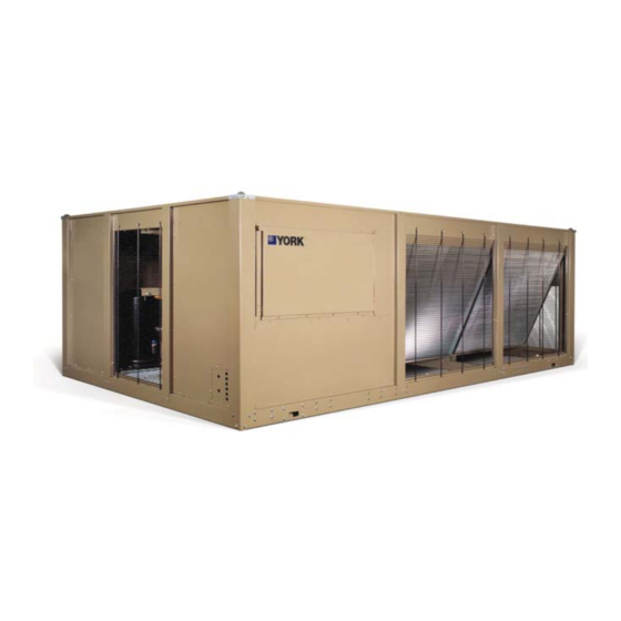
Page 19: Figure 1 - Ycal Air-Cooled Scroll Chillers
FORM 150.67-NM1 ISSUE DATE: 4/28/2017 SECTION 2 – PRODUCT DESCRIPTION INTRODUCTION YORK Millennium® Air-Cooled Scroll Chillers pro- All exposed power wiring is routed through liquid- vide chilled water for all air conditioning applications tight, non-metallic conduit. using central station air handling or terminal units. They... -
Page 20: Condenser
FORM 150.67-NM1 SECTION 2 – PRODUCT DESCRIPTION ISSUE DATE: 4/28/2017 The heat exchanger is a brazed plate stainless steel con- Display/Print struction, single or dual circuit heat exchanger capable Color coded 12-button non-tactile keypad with sec- of refrigerant working pressure of 650 PSIG (3103 tions for display and print of typical information: kPa) and liquid side pressure of 150 PSIG (1034 kPa) -
Page 21: Unit On/Off Switch
• Discharge pressure (optional) The operating program is stored in non-volatile mem- ory (EPROM) to eliminate chiller failure due to AC • Liquid Temperature Reset via a YORK ISN DDC powered failure/battery discharge. Programmed set- or Building Automation System (by others) via: points are retained in lithium battery-backed RTC • a pulse width modulated (PWM) input as... -
Page 22: Discharge Pressure Transducers And Readout Capability
The standard control panel can be directly handle (in compliance with N.E.C. Article 440-14), can connected to a YORK Building Automated System via be supplied to isolate the power voltage for servicing (this the standard onboard RS485 communication port. -
Page 23: Suction Pressure Transducers
Hot gas by-pass is installed on only re- frigerant system #1 on two-circuited units (Factory- Permits unit to sense and display suction pressure. Mounted). This capability is standard on YCAL0019 through YCAL0066 models. Heat Exchanger 300 PSIG (21 BARG) DWP Waterside... -
Page 24: Pre-Coated Fin Condenser Coils
Enclosure Panels can provide an aesthetical- ly pleasing alternative to expensive fencing. Additionally, Lower RPM, 8-pole fan motors are used with steeper- for proper head pressure control, YORK recommends the pitch fans (Factory-Mounted). use of Louvered Panels (described below). -
Page 25: Unit Components Ycal0019 - 0033
FORM 150.67-NM1 SECTION 2 – PRODUCT DESCRIPTION ISSUE DATE: 4/28/2017 UNIT COMPONENTS YCAL0019 - 0033 FAN ASSEMBLIES CONTROL / POWER PANEL CONDENSER COILS HEAT EXCHANGER COMPRESSORS FIGURE 2 - UNIT COMPONENTS SINGLE SYSTEM UNITS JOHNSON CONTROLS... -
Page 26: Control - Power Panel Components Ycal0019-0033
FORM 150.67-NM1 SECTION 2 – PRODUCT DESCRIPTION ISSUE DATE: 4/28/2017 CONTROL - POWER PANEL COMPONENTS YCAL0019-0033 CIRCUIT BREAKER UNIT SWITCH KEYPAD AND DISPLAY USER TERMINAL BLOCK COMPRESSOR CONTACTORS LD11463 FIGURE 3 - CONTROL/POWER PANEL COMPONENTS SINGLE SYSTEM UNITS JOHNSON CONTROLS... -
Page 27: Unit Components - Ycal0043 - 0066
FORM 150.67-NM1 SECTION 2 – PRODUCT DESCRIPTION ISSUE DATE: 4/28/2017 UNIT COMPONENTS - YCAL0043 – 0066 FAN ASSEMBLIES CONDENSER COILS HEAT EXCHANGER LD12477 CONTROL / COMPRESSORS POWER PANEL FIGURE 4 - UNIT COMPONENTS DUAL SYSTEM UNITS JOHNSON CONTROLS... -
Page 28: Control / Power Panel Components - Ycal0043 - 0066
FORM 150.67-NM1 SECTION 2 – PRODUCT DESCRIPTION ISSUE DATE: 4/28/2017 CONTROL / POWER PANEL COMPONENTS - YCAL0043 – 0066 TERMINAL BLOCK FAN FUSES CR1 / CR2 COMPRESSOR CONTACTS CTB1 LD11458a FIGURE 5 - CONTROL/POWER PANEL COMPONENTS DUAL SYSTEM UNITS JOHNSON CONTROLS... -
Page 29: Product Identification Number (Pin)
UNIT DESIGNATOR REFRIGERANT VOLTAGE/STARTER DESIGN/DEVELOPMENT LEVEL : R-410A : Design Series E : 200 / 3/ 60 : YORK : High Efficiency : Engineering : 230 / 3 / 60 : Chiller Change : 380 / 3 / 60 : Air-Cooled... - Page 30 FORM 150.67-NM1 SECTION 2 – PRODUCT DESCRIPTION ISSUE DATE: 4/28/2017 PRODUCT IDENTIFICATION NUMBER (PIN) (CONT’D) FEATURE DESCRIPTION OPTION DESCRIPTION High Ambient Kits Required Ambient Kits (PIN 20) Both Low/High Ambient Kits Required Special Ambient Kits Required No BAS Reset/Offset Required LON E-Link Kit BAS Reset/Offset (PIN 21) SC-Equip Board...
- Page 31 FORM 150.67-NM1 SECTION 2 – PRODUCT DESCRIPTION ISSUE DATE: 4/28/2017 PRODUCT IDENTIFICATION NUMBER (PIN) (CONT’D) FEATURE DESCRIPTION OPTION DESCRIPTION Standard Insulation Insulation (PIN 39) Double Thick Insulation Special Insulation Required Standard Victaulic FLANGES Flanges (PIN 40) Victaulic to Flange Adapter Special Flanges Required No Flow Switch Required One Flow Switch Required...
- Page 32 FORM 150.67-NM1 SECTION 2 – PRODUCT DESCRIPTION ISSUE DATE: 4/28/2017 PRODUCT IDENTIFICATION NUMBER (PIN) (CONT’D) FEATURE DESCRIPTION OPTION DESCRIPTION No Isolators Required 1” Deflection Isolators Required ISOL Vibration Isolators (PIN 54) Neoprene Isolators Required Seismic Isolators Required Special Isolators Required 18 months parts only (year 1) 18 months labor (year 1) (entire unit) 30 months parts (year 1&2) (entire unit)
-
Page 33: Refrigerant Flow Diagram
FORM 150.67-NM1 SECTION 2 – PRODUCT DESCRIPTION ISSUE DATE: 4/28/2017 REFRIGERANT FLOW DIAGRAM AIR COOLED CONDENSERS HOT DISCHARGE GAS LINE OPTIONAL OPTIONAL DISCHARGE LINE BALL VALVE OPTIONAL SERVICE VALVE LD11417 FIGURE 6 - REFRIGERANT FLOW DIAGRAM JOHNSON CONTROLS... - Page 34 FORM 150.67-NM1 SECTION 2 – PRODUCT DESCRIPTION ISSUE DATE: 4/28/2017 THIS PAGE INTENTIONALLY LEFT BLANK JOHNSON CONTROLS...
-
Page 35: Section 3 - Handling And Storage
Figure 8). • To prevent inadvertent operation of the pressure relief devices the unit must not be steam cleaned. MOVING THE CHILLER (YCAL0019 – 0033 SINGLE CIRCUIT ONLY) • It is recommended that the unit is periodically in- Prior to moving the unit, ensure that the installation spected during storage. -
Page 36: Unit Rigging
The thickness of the fork blade must be smaller then the opening of the lifting hole. Improper fork positioning could result in damage to the unit. FIGURE 7 - UNIT RIGGING/LIFTING (YCAL0019 – 0033 SINGLE CIRCUIT MODELS ONLY) JOHNSON CONTROLS... -
Page 37: Figure 8 - Unit Rigging/Lifting (Ycal0043- 0066 Dual Circuit Models)
FORM 150.67-NM1 SECTION 3 – HANDLING AND STORAGE ISSUE DATE: 4/28/2017 Use spreader bars to avoid lifting chains hitting the chiller. Never lift the chiller using a forklift or by hooking to the top rails. Use only the lifting holes provided. Lifting Instructions are placed on a label on the chiller and on the shipping bag. - Page 38 FORM 150.67-NM1 SECTION 3 – HANDLING AND STORAGE ISSUE DATE: 4/28/2017 THIS PAGE INTENTIONALLY LEFT BLANK JOHNSON CONTROLS...
-
Page 39: Section 4 - Installation
FORM 150.67-NM1 ISSUE DATE: 4/28/2017 SECTION 4 – INSTALLATION To ensure warranty coverage, this INSPECTION equipment must be commissioned Immediately upon receiving the unit, it should be in- and serviced by an authorized John- spected for possible damage which may have occurred son Controls service mechanic or a during transit. -
Page 40: Rooftop Locations
Con- them accessible. siderations should be made utilizing noise levels pub- lished in the YORK Engineering Guide for the specific The piping to and from the cooler must be designed to chiller model. Sound blankets for the compressors and suit the individual installation. -
Page 41: Pipework Arrangement
FORM 150.67-NM1 SECTION 4 – INSTALLATION ISSUE DATE: 4/28/2017 size of the pipe in which it is to be installed (see DUCT WORK CONNECTION manufacturer’s instructions furnished with the General Requirements switch). The switch is to be wired to terminals 13 and 14 of CTB1 located in the control panel, as The following duct work recommendations are intend- shown on the unit wiring diagram. -
Page 42: Evaporator Pump Start Contacts
FORM 150.67-NM1 SECTION 4 – INSTALLATION ISSUE DATE: 4/28/2017 acteristics that may cause loose terminations result- Remote Start/Stop Contacts ing from the contraction and expansion of the wiring. To remotely start and stop the chiller, dry contacts Aluminum oxide may also build up at the termination can be wired in series with the flow switch and CTB1 causing hot spots and eventual failure. -
Page 43: Compressor Heaters
FORM 150.67-NM1 SECTION 4 – INSTALLATION ISSUE DATE: 4/28/2017 COMPRESSOR HEATERS RELIEF VALVES Compressor heaters are standard. Non-standard appli- Relief valves are located on both the high and low pres- cations are as follows: sure side of the piping. High side relief valve pressure setting is 650 PSIG. -
Page 44: Figure 10 - Single-Point Supply Connection - Terminal Block, Non-Fused Disconnect Switch Or Circuit Breaker
FORM 150.67-NM1 SECTION 4 – INSTALLATION ISSUE DATE: 4/28/2017 SINGLE-POINT SUPPLY CONNECTION – TERMINAL BLOCK, NON-FUSED DISCONNECT SWITCH OR CIRCUIT BREAKER Power Panel Power Panel Power Panel Control Panel Control Panel Control Panel Terminal Block, Terminal Block, MICROPANEL MICROPANEL NF Disconnect SW NF Disconnect SW or Circuit Breaker or Circuit Breaker... -
Page 45: Control Wiring
FORM 150.67-NM1 SECTION 4 – INSTALLATION ISSUE DATE: 4/28/2017 CONTROL WIRING FLOW SW REMOTE START/STOP LOAD LIMIT INPUT CTB1 LD07725A * Factory wired with optional transformer. CTB2 LD07730 It is possible that multiple sources of The unit evaporator heater uses power can be supplying the unit power 120VAC. - Page 46 FORM 150.67-NM1 SECTION 4 – INSTALLATION ISSUE DATE: 4/28/2017 THIS PAGE INTENTIONALLY LEFT BLANK JOHNSON CONTROLS...
-
Page 47: Section 5 - Technical Data
FORM 150.67-NM1 ISSUE DATE: 4/28/2017 SECTION 5 – TECHNICAL DATA OPERATIONAL LIMITATIONS (ENGLISH) TABLE 1 - TEMPERATURES AND FLOWS ENGLISH LEAVING WATER COOLER FLOW (GPM) AIR ON CONDENSER ( °F) TEMPERATURE ( °F) YCAL MINIMUM MAXIMUM MINIMUM MAXIMUM MINIMUM MAXIMUM 0019 0022 0028... - Page 48 FORM 150.67-NM1 SECTION 5 – TECHNICAL DATA ISSUE DATE: 4/28/2017 YCAL0019-0033 HEAT EXCHANGER FLOW, GPM ENGLISH 1000.0 100.0 10.0 1000 FLOW, GPM LD14085 YCAL COOLER CURVE 0019 0022 0028 0033 Note: Water Pressure Drop Curves may extend past the minimum and maximum water flow ranges.
- Page 49 FORM 150.67-NM1 SECTION 5 – TECHNICAL DATA ISSUE DATE: 4/28/2017 YCAL0043-0066 HEAT EXCHANGER FLOW, GPM ENGLISH 1000 FLOW, GPM LD12451 YCAL COOLER CURVE 0043 0046 0052 0056 0066 Note: Water Pressure Drop Curves may extend past the minimum and maximum water flow ranges. JOHNSON CONTROLS...
-
Page 50: Operational Limitations (Si)
1. For leaving brine temperature below 40 °F (4.4 °C), contact your nearest YORK Office for application requirements. 2. For leaving water temperature higher than 55 °F (12.8 °C), contact the nearest YORK Office for application guidelines. 3. The evaporator is protected against freezing to -20 °F (-28.8 °C) with an electric heater as standard. - Page 51 FORM 150.67-NM1 SECTION 5 – TECHNICAL DATA ISSUE DATE: 4/28/2017 OPERATIONAL LIMITATIONS (SI) YCAL0019-0033 HEAT EXCHANGER FLOW, GPM 1000.0 100.0 10.0 LD14086 FLOW, L/S YCAL COOLER CURVE 0019 0022 0028 0033 Note: Water Pressure Drop Curves may extend past the minimum and maximum water flow ranges.
- Page 52 FORM 150.67-NM1 SECTION 5 – TECHNICAL DATA ISSUE DATE: 4/28/2017 OPERATIONAL LIMITATIONS (SI) YCAL0043-0066 HEAT EXCHANGER FLOW, GPM 1000 FLOW, L/S LD12452 YCAL COOLER CURVE 0043 0046 0052 0056 0066 Note: Water Pressure Drop Curves may extend past the minimum and maximum water flow ranges. JOHNSON CONTROLS...
-
Page 53: Physical Data (English)
FORM 150.67-NM1 SECTION 5 – TECHNICAL DATA ISSUE DATE: 4/28/2017 PHYSICAL DATA (ENGLISH) YCAL0019_ – YCAL0066_ 60Hz TABLE 6 - PHYSICAL DATA (ENGLISH) YCAL REFRIGERANT R-410A STANDARD EFFICIENCY UNITS MODEL YCAL00 LENGTH 109.8 109.8 118.6 118.6 144.8 144.8 148.8 148.8 153.6 WIDTH 44.7... -
Page 54: Electrical Data (English)
FORM 150.67-NM1 SECTION 5 – TECHNICAL DATA ISSUE DATE: 4/28/2017 ELECTRICAL DATA (ENGLISH) (Without Pump) YCAL0019_ – YCAL0066_ Single-Point Field Supplied Power Wiring (See Figure 12) (One Field Provided Power Supply to the chiller. Field connections to Factory Provided Power Terminal Block (standard), Non-Fused Disconnect Switch (optional) or Circuit Breaker (optional)). - Page 55 FORM 150.67-NM1 SECTION 5 – TECHNICAL DATA ISSUE DATE: 4/28/2017 ELECTRICAL DATA (ENGLISH) (CONT’D) YCAL0019_ – YCAL0066_ Single-Point Field Supplied Power Wiring (See Figure 12) (One Field Provided Power Supply to the chiller. Field connections to Factory Provided Power Terminal Block (standard), Non-Fused Disconnect Switch (optional) or Circuit Breaker (optional)).
- Page 56 FORM 150.67-NM1 SECTION 5 – TECHNICAL DATA ISSUE DATE: 4/28/2017 ELECTRICAL DATA (ENGLISH) YCAL0019_ – YCAL0066_ (CON’T.) (Without Pump) Single-Point Field Supplied Power Wiring (See Figure 12) (One Field Provided Power Supply to the chiller. Field connections to Factory Provided Power Terminal Block (standard), Non-Fused Disconnect Switch (optional) or Circuit Breaker (optional)).
- Page 57 FORM 150.67-NM1 SECTION 5 – TECHNICAL DATA ISSUE DATE: 4/28/2017 ELECTRICAL DATA (ENGLISH) (CONT’D) YCAL0019_ – YCAL0066_ Single-Point Field Supplied Power Wiring (See Figure 12) (One Field Provided Power Supply to the chiller. Field connections to Factory Provided Power Terminal Block (standard), Non-Fused Disconnect Switch (optional) or Circuit Breaker (optional)).
-
Page 58: Table 8 - Micro Panel Power Supply
FORM 150.67-NM1 SECTION 5 – TECHNICAL DATA ISSUE DATE: 4/28/2017 ELECTRICAL DATA TABLE 8 - MICRO PANEL POWER SUPPLY OVER CURRENT PROTECTION, CONTROL UNIT VOLTAGE SEE NOTE B NF DISC SW POWER NOTE A UNIT MINIMUM MAXIMUM MODELS W/O VOLTAGE CONTROL 115-1-60/50 30 A / 240V... -
Page 59: Electrical Notes And Legend
FORM 150.67-NM1 SECTION 5 – TECHNICAL DATA ISSUE DATE: 4/28/2017 ELECTRICAL NOTES AND LEGEND NOTES: 1. Minimum Circuit Ampacity (MCA) is based on 125% of the rated load amps for the largest motor plus 100% of the rated load amps for all other loads included in the circuit, per N.E.C. Article 430-24. If the optional Fac- tory Mounted Control Transformer is provided, add the following MCA values to the electrical tables for the system providing power to the transformer: -17, add 2.5 amps;... -
Page 60: Figure 12 - Control Wiring Diagram, Single Circuit, Ipu Ii
FORM 150.67-NM1 SECTION 5 – TECHNICAL DATA ISSUE DATE: 4/28/2017 CONTROL WIRING DIAGRAMS YCAL0019-YCAL0022 LOW SOUND YCAL0028-YCAL0033 ULTRA LOW SOUND (460V AND 380-415V 50 HZ) LD22088a FIGURE 12 - CONTROL WIRING DIAGRAM, SINGLE CIRCUIT, IPU II JOHNSON CONTROLS... - Page 61 FORM 150.67-NM1 SECTION 5 – TECHNICAL DATA ISSUE DATE: 4/28/2017 035-21472-401 REV E LD22088b JOHNSON CONTROLS...
- Page 62 FORM 150.67-NM1 SECTION 5 – TECHNICAL DATA ISSUE DATE: 4/28/2017 YCAL0028-YCAL0033 ULTRA LOW SOUND (200V, 230V, 380V, AND 575V) LD22078a FIGURE 13 - CONTROL WIRING DIAGRAM, SINGLE CIRCUIT, IPU II JOHNSON CONTROLS...
-
Page 63: Figure 13 - Control Wiring Diagram, Single Circuit, Ipu Ii
FORM 150.67-NM1 SECTION 5 – TECHNICAL DATA ISSUE DATE: 4/28/2017 035-21585-401 REV E LD22078b JOHNSON CONTROLS... -
Page 64: Figure 14 - Control Wiring Diagram, Dual Circuit, Ipu Ii
FORM 150.67-NM1 SECTION 5 – TECHNICAL DATA ISSUE DATE: 4/28/2017 YCAL0043-YCAL0052 LOW SOUND YCAL0043-YCAL0052 ULTRA LOW SOUND (460V AND 380-415V 50 HZ) LDxxxxx LD22079a FIGURE 14 - CONTROL WIRING DIAGRAM, DUAL CIRCUIT, IPU II JOHNSON CONTROLS... - Page 65 FORM 150.67-NM1 SECTION 5 – TECHNICAL DATA ISSUE DATE: 4/28/2017 035-21447-401 REV D LD22079b JOHNSON CONTROLS...
-
Page 66: Figure 15 - Control Wiring Diagram, Dual Circuit, Ipu Ii
FORM 150.67-NM1 SECTION 5 – TECHNICAL DATA ISSUE DATE: 4/28/2017 YCAL0056-YCAL0066 LOW SOUND YCAL0043-YCAL0052 ULTRA LOW SOUND (200V, 230V, 380V AND 575V) LD22080a FIGURE 15 - CONTROL WIRING DIAGRAM, DUAL CIRCUIT, IPU II JOHNSON CONTROLS... - Page 67 FORM 150.67-NM1 SECTION 5 – TECHNICAL DATA ISSUE DATE: 4/28/2017 035-21586-401 REV D LD22080b JOHNSON CONTROLS...
-
Page 68: Figure 16 - Control Wiring Diagram, Details, Single Circuit
FORM 150.67-NM1 SECTION 5 – TECHNICAL DATA ISSUE DATE: 4/28/2017 YCAL0019-YCAL0022 LOW SOUND YCAL0028-YCAL0033 ULTRA LOW SOUND 035-20964-103 REV C Notes: I. Field wiring to be in accordance with the current edition of the National Electrical Code as well as all other applicable codes and speci- fications. - Page 69 FORM 150.67-NM1 SECTION 5 – TECHNICAL DATA ISSUE DATE: 4/28/2017 JOHNSON CONTROLS...
-
Page 70: Figure 17 - Control Wiring Diagram, Details, Dual Circuit
FORM 150.67-NM1 SECTION 5 – TECHNICAL DATA ISSUE DATE: 4/28/2017 YCAL0043-YCAL0052 LOW SOUND YCAL0043-YCAL0052 ULTRA LOW SOUND 035-20880-103 REV C Notes: I. Field wiring to be in accordance with the current edition of the National Electrical Code as well as all other applicable codes and speci- fications. - Page 71 FORM 150.67-NM1 SECTION 5 – TECHNICAL DATA ISSUE DATE: 4/28/2017 JOHNSON CONTROLS...
-
Page 72: Figure 18 - Power Wiring, Single Circuit
FORM 150.67-NM1 SECTION 5 – TECHNICAL DATA ISSUE DATE: 4/28/2017 POWER OPTIONS CONNECTION DIAGRAMS YCAL0019-YCAL0022 LOW SOUND (200V, 230V, 380V, 460V AND 575V) LD22081a FIGURE 18 - POWER WIRING, SINGLE CIRCUIT JOHNSON CONTROLS... - Page 73 FORM 150.67-NM1 SECTION 5 – TECHNICAL DATA ISSUE DATE: 4/28/2017 035-21487-102 REV A LD22081b JOHNSON CONTROLS...
-
Page 74: Figure 19 - Power Wiring, Single Circuit
FORM 150.67-NM1 SECTION 5 – TECHNICAL DATA ISSUE DATE: 4/28/2017 YCAL0019-YCAL0022 LOW SOUND (380-415V/3/50) LD22082a FIGURE 19 - POWER WIRING, SINGLE CIRCUIT JOHNSON CONTROLS... - Page 75 FORM 150.67-NM1 SECTION 5 – TECHNICAL DATA ISSUE DATE: 4/28/2017 035-21487-105 REV B LD22082b JOHNSON CONTROLS...
-
Page 76: Figure 20 - Power Wiring, Single Circuit
FORM 150.67-NM1 SECTION 5 – TECHNICAL DATA ISSUE DATE: 4/28/2017 YCAL0028-YCAL0033 LOW SOUND YCAL0028-YCAL0033 ULTRA LOW SOUND (460V AND 380-415V/3/50) LD22083a FIGURE 20 - POWER WIRING, SINGLE CIRCUIT JOHNSON CONTROLS... - Page 77 FORM 150.67-NM1 SECTION 5 – TECHNICAL DATA ISSUE DATE: 4/28/2017 035-21472-102 REV D LD22083b JOHNSON CONTROLS...
-
Page 78: Figure 21 - Power Wiring, Single Circuit
FORM 150.67-NM1 SECTION 5 – TECHNICAL DATA ISSUE DATE: 4/28/2017 YCAL0028-YCAL0033 ULTRA LOW SOUND (200V, 230V, 380V AND 575V) LD22084a FIGURE 21 - POWER WIRING, SINGLE CIRCUIT JOHNSON CONTROLS... - Page 79 FORM 150.67-NM1 SECTION 5 – TECHNICAL DATA ISSUE DATE: 4/28/2017 035-21585-102 REV C LD22083b JOHNSON CONTROLS...
-
Page 80: Figure 22 - Power Wiring, Dual Circuit
FORM 150.67-NM1 SECTION 5 – TECHNICAL DATA ISSUE DATE: 4/28/2017 YCAL0043-YCAL0052 LOW SOUND YCAL0043-YCAL0052 ULTRA LOW SOUND (460V AND 380-415V 50 HZ) LD21830a FIGURE 22 - POWER WIRING, DUAL CIRCUIT JOHNSON CONTROLS... - Page 81 FORM 150.67-NM1 SECTION 5 – TECHNICAL DATA ISSUE DATE: 4/28/2017 035-21447-102 REV A LD21830b JOHNSON CONTROLS...
-
Page 82: Figure 23 - Power Wiring, Dual Circuit
FORM 150.67-NM1 SECTION 5 – TECHNICAL DATA ISSUE DATE: 4/28/2017 YCAL0056-YCAL0066 LOW SOUND YCAL0043-YCAL0052 ULTRA LOW SOUND (200V, 230V, 380V AND 575V) FIGURE 23 - POWER WIRING, DUAL CIRCUIT LD22086a JOHNSON CONTROLS... - Page 83 FORM 150.67-NM1 SECTION 5 – TECHNICAL DATA ISSUE DATE: 4/28/2017 035-21025-102 REV C LD22085b JOHNSON CONTROLS...
-
Page 84: Figure 24 - Connection Wiring, Single Circuit
FORM 150.67-NM1 SECTION 5 – TECHNICAL DATA ISSUE DATE: 4/28/2017 CONNECTION WIRING DIAGRAMS YCAL0019-YCAL0022 LOW SOUND (200V, 230V, 380V, 460V AND 575V) LD21822a FIGURE 24 - CONNECTION WIRING, SINGLE CIRCUIT JOHNSON CONTROLS... - Page 85 FORM 150.67-NM1 SECTION 5 – TECHNICAL DATA ISSUE DATE: 4/28/2017 035-21487-404 REV C LD21822b JOHNSON CONTROLS...
-
Page 86: Figure 25 - Connection Wiring, Single Circuit
FORM 150.67-NM1 SECTION 5 – TECHNICAL DATA ISSUE DATE: 4/28/2017 YCAL0019-YCAL0022 LOW SOUND (380-415V/3/50) LD21823a FIGURE 25 - CONNECTION WIRING, SINGLE CIRCUIT JOHNSON CONTROLS... - Page 87 FORM 150.67-NM1 SECTION 5 – TECHNICAL DATA ISSUE DATE: 4/28/2017 035-21487-406 Rev D LD21823b JOHNSON CONTROLS...
-
Page 88: Figure 26 - Connection Wiring, Single Circuit
FORM 150.67-NM1 SECTION 5 – TECHNICAL DATA ISSUE DATE: 4/28/2017 YCAL0028-YCAL0033 LOW SOUND YCAL0028-YCAL0033 ULTRA LOW SOUND (460V AND 380-415V/3/50) LD21824a FIGURE 26 - CONNECTION WIRING, SINGLE CIRCUIT JOHNSON CONTROLS... - Page 89 FORM 150.67-NM1 SECTION 5 – TECHNICAL DATA ISSUE DATE: 4/28/2017 035-21472-404 REV C LD21824b JOHNSON CONTROLS...
-
Page 90: Figure 27 - Connection Wiring, Single Circuit
FORM 150.67-NM1 SECTION 5 – TECHNICAL DATA ISSUE DATE: 4/28/2017 YCAL0028-YCAL0033 ULTRA LOW SOUND (200V, 230V, 380V AND 575V) LD22087a FIGURE 27 - CONNECTION WIRING, SINGLE CIRCUIT JOHNSON CONTROLS... - Page 91 FORM 150.67-NM1 SECTION 5 – TECHNICAL DATA ISSUE DATE: 4/28/2017 035-21585-404 REV D LD22087b JOHNSON CONTROLS...
-
Page 92: Figure 28 - Connection Wiring, Dual Circuit
FORM 150.67-NM1 SECTION 5 – TECHNICAL DATA ISSUE DATE: 4/28/2017 YCAL0043-YCAL0052 LOW SOUND YCAL0043-YCAL0052 ULTRA LOW SOUND (460V AND 380-415V 50 HZ) FIGURE 28 - CONNECTION WIRING, DUAL CIRCUIT LD19120 JOHNSON CONTROLS... - Page 93 FORM 150.67-NM1 SECTION 5 – TECHNICAL DATA ISSUE DATE: 4/28/2017 035-21447-404 REV B LD19121 JOHNSON CONTROLS...
-
Page 94: Figure 29 - Connection Wiring, Dual Circuit
FORM 150.67-NM1 SECTION 5 – TECHNICAL DATA ISSUE DATE: 4/28/2017 YCAL0056-YCAL0066 LOW SOUND YCAL0043-YCAL0052 ULTRA LOW SOUND (200V, 230V, 380V AND 575V) LD19122 FIGURE 29 - CONNECTION WIRING, DUAL CIRCUIT JOHNSON CONTROLS... - Page 95 FORM 150.67-NM1 SECTION 5 – TECHNICAL DATA ISSUE DATE: 4/28/2017 035-21586-404 REV B LD19123 JOHNSON CONTROLS...
- Page 96 Site restrictions may compromise minimum clearances indicated below, resulting in unpredictable airflow patterns and possible diminished performance. YORK’s unit controls will optimize operation without nuisance high-pressure safety cutouts; however, the system designer must consider potential performance degradation. Recommended minimum clearances: front to wall – 6'; rear to wall –...
- Page 97 FORM 150.67-NM1 SECTION 5 – TECHNICAL DATA ISSUE DATE: 4/28/2017 DIMENSIONS – YCAL0019 (ENGLISH) (CONT’D) 9/16" DIA MOUNTING HOLES(typ) 1 1/16" CONTROL COMPR PANEL 44 3/8" END CAP WIDTH 32 1/8" 6 1/8" 1 1/16" ORIGIN 2 1/4" 5" TOP VIEW 17"...
- Page 98 Site restrictions may compromise minimum clearances indicated below, resulting in unpredictable airflow patterns and possible diminished performance. YORK’s unit controls will optimize operation without nuisance high-pressure safety cutouts; however, the system designer must consider potential performance degradation. Recommended minimum clearances: front to wall – 6'; rear to wall –...
- Page 99 FORM 150.67-NM1 SECTION 5 – TECHNICAL DATA ISSUE DATE: 4/28/2017 DIMENSIONS – YCAL0022 (ENGLISH) (CONT’D) 9/16" DIA MOUNTING HOLES(typ) 1 1/16" CONTROL COMPR PANEL 44 3/8" END CAP WIDTH 32 1/8" 6 1/8" 1 1/16" ORIGIN 2 1/4" 5" TOP VIEW 17"...
- Page 100 Site restrictions may compromise minimum clearances indicated below, resulting in unpredictable airflow patterns and possible diminished performance. YORK’s unit controls will optimize operation without nuisance high-pressure safety cutouts; however, the system designer must consider potential performance degradation. Recommended minimum clearances: front to wall – 6'; rear to wall –...
- Page 101 FORM 150.67-NM1 SECTION 5 – TECHNICAL DATA ISSUE DATE: 4/28/2017 DIMENSIONS – YCAL0028 (ENGLISH) (CONT’D) 5/8" DIA MOUNTING HOLES(TYP) 1 1/16" CONTROL COMPR PANEL 44 3/8" END CAP WIDTH 32 1/8" 6 1/8" 1 1/16" 1 7/8" ORIGIN 5" 17" TOP VIEW R-410A CHILLER 1"...
- Page 102 Site restrictions may compromise minimum clearances indicated below, resulting in unpredictable airflow patterns and possible diminished performance. YORK’s unit controls will optimize operation without nuisance high-pressure safety cutouts; however, the system designer must consider potential performance degradation. Recommended minimum clearances: front to wall – 6'; rear to wall –...
- Page 103 FORM 150.67-NM1 SECTION 5 – TECHNICAL DATA ISSUE DATE: 4/28/2017 DIMENSIONS – YCAL0033 (ENGLISH) (CONT’D) 9/16" DIA MOUNTING HOLES(typ) 1 1/16" CONTROL COMPR PANEL 44 3/8" END CAP WIDTH 32 1/8" 6 1/8" 1 1/16" 1 7/8" ORIGIN 5" 17" TOP VIEW 1"...
- Page 104 Site restrictions may compromise minimum clearances indicated below, resulting in unpredictable airflow patterns and possible diminished performance. YORK’s unit controls will optimize operation without nuisance high-pressure safety cutouts; however, the system designer must consider potential performance degradation. Recommended minimum clearances: front to wall – 6'; rear to wall –...
- Page 105 FORM 150.67-NM1 SECTION 5 – TECHNICAL DATA ISSUE DATE: 4/28/2017 DIMENSIONS – YCAL0043 (ENGLISH) (CONT’D) 9/16" DIA MOUNTING HOLES(typ) 1 1/16" COIL COOLER 90 9/16" END CAP WIDTH 45 5/16" 1 1/16" 9 13/16" 9 13/16" ORIGIN 21 13/16" TOP VIEW 5 5/16"...
- Page 106 Site restrictions may compromise minimum clearances indicated below, resulting in unpredictable airflow patterns and possible diminished performance. YORK’s unit controls will optimize operation without nuisance high-pressure safety cutouts; however, the system designer must consider potential performance degradation. Recommended minimum clearances: front to wall – 6'; rear to wall –...
- Page 107 FORM 150.67-NM1 SECTION 5 – TECHNICAL DATA ISSUE DATE: 4/28/2017 DIMENSIONS – YCAL0046 (ENGLISH) (CONT’D) 9/16" DIA MOUNTING HOLES(typ) 1 1/16" COIL COOLER 90 9/16" END CAP WIDTH 45 5/16" 1 1/16" 9 13/16" 9 13/16" ORIGIN TOP VIEW 20 1/16" 5 5/16"...
- Page 108 Site restrictions may compromise minimum clearances indicated below, resulting in unpredictable airflow patterns and possible diminished performance. YORK’s unit controls will optimize operation without nuisance high-pressure safety cutouts; however, the system designer must consider potential performance degradation. Recommended minimum clearances: front to wall – 6'; rear to wall –...
- Page 109 FORM 150.67-NM1 SECTION 5 – TECHNICAL DATA ISSUE DATE: 4/28/2017 DIMENSIONS – YCAL0052 (ENGLISH) (CONT’D) 5/8" DIA MOUNTING HOLES(TYP) 1 1/16" COIL COOLER 90 9/16" END CAP WIDTH 45 5/16" 1 1/16" 9 13/16" 9 13/16" ORIGIN TOP VIEW 20 1/16" R-410A CHILLER 5 5/16"...
- Page 110 Site restrictions may compromise minimum clearances indicated below, resulting in unpredictable airflow patterns and possible diminished performance. YORK’s unit controls will optimize operation without nuisance high-pressure safety cutouts; however, the system designer must consider potential performance degradation. Recommended minimum clearances: front to wall – 6'; rear to wall –...
- Page 111 FORM 150.67-NM1 SECTION 5 – TECHNICAL DATA ISSUE DATE: 4/28/2017 DIMENSIONS – YCAL0056 (ENGLISH) (CONT’D) 5/8" DIA MOUNTING HOLES(TYP) 1 1/16" COIL COOLER 90 9/16" END CAP WIDTH 45 5/16" 1 1/16" 1,015 ORIGIN 9 13/16" 9 13/16" TOP VIEW 18 7/16"...
- Page 112 Site restrictions may compromise minimum clearances indicated below, resulting in unpredictable airflow patterns and possible diminished performance. YORK’s unit controls will optimize operation without nuisance high-pressure safety cutouts; however, the system designer must consider potential performance degradation. Recommended minimum clearances: front to wall – 6'; rear to wall –...
- Page 113 FORM 150.67-NM1 SECTION 5 – TECHNICAL DATA ISSUE DATE: 4/28/2017 DIMENSIONS – YCAL0066 (ENGLISH) (CONT’D) 9/16" DIA MOUNTING HOLES(typ) 1 1/16" COIL COOLER 90 9/16" END CAP WIDTH 43 5/16" 1 1/16" ORIGIN 9 13/16" 9 13/16" 16 11/16" TOP VIEW 5 3/16"...
- Page 114 Site restrictions may compromise minimum clearances indicated below, resulting in unpredictable airflow patterns and possible diminished performance. YORK’s unit controls will optimize operation without nuisance high-pressure safety cutouts; however, the system designer must consider potential performance degradation. Recommended minimum clearances: front to wall – 2m; rear to wall –...
- Page 115 FORM 150.67-NM1 SECTION 5 – TECHNICAL DATA ISSUE DATE: 4/28/2017 DIMENSIONS – YCAL0019 (SI) (CONT’D) 14 DIA MOUNTING HOLES(typ) CONTROL COMPR PANEL 1128 END CAP WIDTH ORIGIN TOP VIEW CONTROL PANEL (2) 178 X 57 FORKLIFT HOLES BOTH SIDES (2) 76 X 38...
- Page 116 Site restrictions may compromise minimum clearances indicated below, resulting in unpredictable airflow patterns and possible diminished performance. YORK’s unit controls will optimize operation without nuisance high-pressure safety cutouts; however, the system designer must consider potential performance degradation. Recommended minimum clearances: front to wall – 2m; rear to wall –...
- Page 117 FORM 150.67-NM1 SECTION 5 – TECHNICAL DATA ISSUE DATE: 4/28/2017 DIMENSIONS – YCAL0022 (SI) (CONT’D) 14 DIA MOUNTING HOLES(typ) CONTROL COMPR PANEL 1128 END CAP WIDTH ORIGIN TOP VIEW CONTROL PANEL (2) 178 X 57 FORKLIFT HOLES BOTH SIDES (2) 76 X 38 RIGGING HOLES BOTH SIDES 1130...
- Page 118 Site restrictions may compromise minimum clearances indicated below, resulting in unpredictable airflow patterns and possible diminished performance. YORK’s unit controls will optimize operation without nuisance high-pressure safety cutouts; however, the system designer must consider potential performance degradation. Recommended minimum clearances: front to wall – 2m; rear to wall –...
- Page 119 FORM 150.67-NM1 SECTION 5 – TECHNICAL DATA ISSUE DATE: 4/28/2017 DIMENSIONS – YCAL0028 (SI) (CONT’D) 16 DIA MOUNTING HOLES(TYP) CONTROL COMPR PANEL 1128 END CAP WIDTH ORIGIN TOP VIEW R-410A CHILLER CONTROL PANEL 1070 (2) 178 X 57 FORKLIFT HOLES (2) 76 X 38 BOTH SIDES RIGGING HOLES...
- Page 120 Site restrictions may compromise minimum clearances indicated below, resulting in unpredictable airflow patterns and possible diminished performance. YORK’s unit controls will optimize operation without nuisance high-pressure safety cutouts; however, the system designer must consider potential performance degradation. Recommended minimum clearances: front to wall – 2m; rear to wall –...
- Page 121 FORM 150.67-NM1 SECTION 5 – TECHNICAL DATA ISSUE DATE: 4/28/2017 DIMENSIONS – YCAL0033 (SI) (CONT’D) 14 DIA MOUNTING HOLES(typ) CONTROL COMPR PANEL 1128 END CAP WIDTH ORIGIN TOP VIEW CONTROL PANEL 1070 (2) 178 X 57 FORKLIFT HOLES BOTH SIDES (2) 76 X 38 RIGGING HOLES 1282...
- Page 122 Site restrictions may compromise minimum clearances indicated below, resulting in unpredictable airflow patterns and possible diminished performance. YORK’s unit controls will optimize operation without nuisance high-pressure safety cutouts; however, the system designer must consider potential performance degradation. Recommended minimum clearances: front to wall – 2m; rear to wall –...
- Page 123 FORM 150.67-NM1 SECTION 5 – TECHNICAL DATA ISSUE DATE: 4/28/2017 DIMENSIONS – YCAL0043 (SI) (CONT’D) 14 DIA MOUNTING HOLES(typ) COIL COOLER 2301 END CAP WIDTH 1150 ORIGIN TOP VIEW CONTROL PANEL TWO LIFTING HOLES BOTH SIDES 3678 FRONT VIEW JOHNSON CONTROLS...
- Page 124 Site restrictions may compromise minimum clearances indicated below, resulting in unpredictable airflow patterns and possible diminished performance. YORK’s unit controls will optimize operation without nuisance high-pressure safety cutouts; however, the system designer must consider potential performance degradation. Recommended minimum clearances: front to wall – 2m; rear to wall –...
- Page 125 FORM 150.67-NM1 SECTION 5 – TECHNICAL DATA ISSUE DATE: 4/28/2017 DIMENSIONS – YCAL0046 (SI) (CONT’D) 14 DIA MOUNTING HOLES(typ) COIL COOLER 2301 END CAP WIDTH 1150 ORIGIN TOP VIEW CONTROL PANEL TWO LIFTING HOLES BOTH SIDES 3678 FRONT VIEW JOHNSON CONTROLS...
- Page 126 Site restrictions may compromise minimum clearances indicated below, resulting in unpredictable airflow patterns and possible diminished performance. YORK’s unit controls will optimize operation without nuisance high-pressure safety cutouts; however, the system designer must consider potential performance degradation. Recommended minimum clearances: front to wall – 2m; rear to wall –...
- Page 127 FORM 150.67-NM1 SECTION 5 – TECHNICAL DATA ISSUE DATE: 4/28/2017 DIMENSIONS – YCAL0052 (SI) (CONT’D) 16 DIA MOUNTING HOLES(TYP) COIL COOLER 2301 END CAP WIDTH 1150 ORIGIN TOP VIEW R-410A CHILLER CONTROL PANEL TWO LIFTING HOLES BOTH SIDES 3678 FRONT VIEW JOHNSON CONTROLS...
- Page 128 Site restrictions may compromise minimum clearances indicated below, resulting in unpredictable airflow patterns and possible diminished performance. YORK’s unit controls will optimize operation without nuisance high-pressure safety cutouts; however, the system designer must consider potential performance degradation. Recommended minimum clearances: front to wall – 2m; rear to wall –...
- Page 129 FORM 150.67-NM1 SECTION 5 – TECHNICAL DATA ISSUE DATE: 4/28/2017 DIMENSIONS – YCAL0056 (SI) (CONT’D) 16 DIA MOUNTING HOLES(TYP) COIL COOLER 2301 END CAP WIDTH 1151 1,015 ORIGIN TOP VIEW R-410A CHILLER CONTROL PANEL TWO LIFTING HOLES BOTH SIDES 3678 FRONT VIEW JOHNSON CONTROLS...
- Page 130 Site restrictions may compromise minimum clearances indicated below, resulting in unpredictable airflow patterns and possible diminished performance. YORK’s unit controls will optimize operation without nuisance high-pressure safety cutouts; however, the system designer must consider potential performance degradation. Recommended minimum clearances: front to wall – 2m; rear to wall –...
- Page 131 FORM 150.67-NM1 SECTION 5 – TECHNICAL DATA ISSUE DATE: 4/28/2017 DIMENSIONS – YCAL0066 (SI) (CONT’D) 14 DIA MOUNTING HOLES(typ) COIL COOLER 2301 END CAP WIDTH 1100 ORIGIN TOP VIEW CONTROL PANEL TWO LIFTING HOLES BOTH SIDES 3902 FRONT VIEW JOHNSON CONTROLS...
-
Page 132: Figure 30 - Unit Clearances - All Models
FORM 150.67-NM1 SECTION 5 – TECHNICAL DATA ISSUE DATE: 4/28/2017 TECHNICAL DATA – CLEARANCES (2 m) (1.3 m) LD10506 NOTES: 1. No obstructions allowed above the unit. 2. Only one adjacent wall may be higher than the unit. 3. Adjacent units should be 10 feet (3 Meters) apart. FIGURE 30 - UNIT CLEARANCES –... -
Page 133: General
The selection is made from the local YORK sales office. drawing will show the isolator locations along with the Be aware, weights may change with each option along weight in pounds and kilograms at the specific loca- with possible isolator changes. -
Page 134: Isolator Selection
FORM 150.67-NM1 SECTION 5 – TECHNICAL DATA ISSUE DATE: 4/28/2017 ISOLATOR SELECTION YCAL0019 – 0033 (WITHOUT PUMP PACKAGE OPTION) STANDARD ALUMINUM CONDENSER FINS OPTIONAL COPPER CONDENSER FINS LOCATION 1” CIP-B-450 CIP-B-750 CIP-B-450 CIP-B-750 CIP-B-450 CIP-B-750 CIP-B-450 CIP-B-750 Deflection YCAL0019 Neoprene... -
Page 135: General
The selection is made from the local YORK sales office. drawing will show the isolator locations along with the Be aware, weights will change with each option along weight in pounds and kilograms at the specific loca- with possible isolator changes. -
Page 136: Figure 31 - One Inch Deflection Spring Isolator Cross-Reference
FORM 150.67-NM1 SECTION 5 – TECHNICAL DATA ISSUE DATE: 4/28/2017 ISOLATOR DETAILS - UNITS SHIPPED ON OR AFTER JUNE 15, 2008 ONE INCH DEFLECTION SPRING ISOLATOR CROSS-REFERENCE 5/8" Ø1/2" H" C" T" B" L" D" W" LD13759A DIMENSION DATA (INCHES) MOUNT TYPE 7-3/4... -
Page 137: Figure 32 - One Inch Deflection Spring Isolators Installation Instructions
FORM 150.67-NM1 SECTION 5 – TECHNICAL DATA ISSUE DATE: 4/28/2017 ONE INCH DEFLECTION SPRING ISOLATORS INSTALLATION INSTRUCTIONS Units shipped on or after June 15, 2008 1. Read instructions in their entirety before begin- 5. Place equipment on top of isolators making sure ning installation. -
Page 138: Figure 33 - Durulene Isolator Cross-Reference
FORM 150.67-NM1 SECTION 5 – TECHNICAL DATA ISSUE DATE: 4/28/2017 DURULENE ISOLATOR CROSS-REFERENCE RD-Style Isolators Notes: 1. All dimensions are inches, interpreted per ANSI Y14. MOLDED DURULENE 2. Refer to next page for installation instructions. 3. Mount molded in weather resistant duralene compound as stan- ø... -
Page 139: Figure 34 - Installation Of Durulene Vibration Isolators
FORM 150.67-NM1 SECTION 5 – TECHNICAL DATA ISSUE DATE: 4/28/2017 INSTALLATION OF DURULENE VIBRATION ISOLATORS Units shipped on or after June 15, 2008 1. Read instructions in their entirety before begin- 4. Bolt or anchor all isolators to supporting structure ning installation. -
Page 140: Figure 35 - Two Inch Deflection Seismic Isolator Cross-Reference
FORM 150.67-NM1 SECTION 5 – TECHNICAL DATA Y2RS ISSUE DATE: 4/28/2017 TWO INCH DEFLECTION SEISMIC ISOLATOR CROSS-REFERENCE Units shipped on or after June 15, 2008 1-1/8" 5" 5/8" 2-3/4" 2-3/4" 12" 3/8" GAP 5/8-11UNC Ø3/4" TYP. (4) TYP.(4) 3/4" 7/8" 1/2"... -
Page 141: Figure 36 - Seismic Isolator Installation And Adjustment
FORM 150.67-NM1 SECTION 5 – TECHNICAL DATA ISSUE DATE: 4/28/2017 SEISMIC ISOLATOR INSTALLATION AND ADJUSTMENT Units shipped on or after June 15, 2008 1. Read instructions in their entirety before begin- bolts or weld equipment or bracket to the top plate ning installation. -
Page 142: Figure 37 - One Inch Deflection Spring Isolator Cross-Reference (Cip-X)
BASE PLATE DIMENSIONS FOR UNITS WITH ALL POINT LOADS LESS THAN 1404 LBS (637 KG) WEIGHT RANGE WEIGHT RANGE MODEL NUMBER COLOR YORK P/N (LBS) (KG) 239 TO 384 LBS 108 TO 174 KG CIP-B- 029-24583-002... - Page 143 FORM 150.67-NM1 SECTION 5 – TECHNICAL DATA ISSUE DATE: 4/28/2017 INSTALLATION OF 1" DEFLECTION MOUNTS 1. Floor or steel frame should be level and smooth. 5. Complete piping and fill equipment with water, refrigerant, etc. 2. For pad installations, isolators do not normally require bolting.
-
Page 144: Figure 38 - Neoprene Isolator Cross-Reference
69.9 158.8 101.6 127.0 1/2- 13 X 1” 12.7 WEIGHT RANGE WEIGHT RANGE MODEL NUMBER COLOR YORK P/N (LBS) (KG) UP TO 751 LBS UP TO 341 KG ND-C YELLOW 029-24584-001 751 TO 1651 LBS 341 TO 749 KG ND-D... -
Page 145: Figure 39 - Two Inch Deflection, Seismic Spring Isolator Cross-Reference
215.9 15.9 34.9 355.6 311.2 133.4 88.9 5/8" *WEIGHT RANGE WEIGHT RANGE MODEL NUMBER COLOR YORK P/N (LBS) (KG) UP TO 358 LBS UP TO 162 KG SLRS-2-C2- 029-24585-006 358 TO 443 LBS 162 TO 201 KG SLRS-2-C2- WHITE 029-24585-007... -
Page 146: Figure 40 - Slrs Seismic Isolator Installation And Adjustment
FORM 150.67-NM1 SECTION 5 – TECHNICAL DATA ISSUE DATE: 4/28/2017 SLRS SEISMIC ISOLATOR INSTALLATION AND ADJUSTMENT Units shipped before June 15, 2008 To install and adjust mounts: 8. Turn adjustment bolt 8 turns on each mount. 1. Supports for mountings must be leveled to instal- lation's acceptable tolerances. -
Page 147: Section 6 - Commissioning
SECTION 6 – COMMISSIONING COMMISSIONING Compressor Oil To add oil to a circuit – connect a YORK hand oil pump Commissioning of this unit should (Part No. 470-10654-000) to the 1/4" oil charging con- only be carried out by YORK Autho- nection on the compressors with a length of clean hose rized personnel. -
Page 148: Supply Voltage
FORM 150.67-NM1 SECTION 6 – COMMISSIONING ISSUE DATE: 4/28/2017 Supply Voltage Water System Verify that the site voltage supply corresponds to the Verify the chilled liquid system has been installed cor- unit requirement and is within the limits given in the rectly, and has been commissioned with the correct di- Technical Data Section. -
Page 149: Equipment Start-Up Checklist
FORM 150.67-NM1 SECTION 6 – COMMISSIONING ISSUE DATE: 4/28/2017 EQUIPMENT START-UP CHECKLIST 8. Visually inspect wiring (power and control). Wir- JOB NAME: ______________________________ ing must meet N.E.C. and local codes. SALES ORDER #: _________________________ 9. Check tightness of power wiring inside the power LOCATION: ______________________________ panel on both sides of the motor contactors and SOLD BY: ________________________________... -
Page 150: Table 10 - Setpoints Entry List
FORM 150.67-NM1 SECTION 6 – COMMISSIONING ISSUE DATE: 4/28/2017 cur, the compressor being tested is operating in TABLE 10 - SETPOINTS ENTRY LIST the reverse direction and must be corrected. After OPTIONS verifying proper compressor rotation, turn the Display Language Unit Switch to OFF. -
Page 151: Leak Checking
FORM 150.67-NM1 SECTION 6 – COMMISSIONING ISSUE DATE: 4/28/2017 When adjusting the expansion valve (TXV only), the 1. Record the liquid line pressure and its correspond- adjusting screw should be turned not more than one ing temperature, liquid line temperature and turn at a time, allowing sufficient time (approximately subcooling below: 15 minutes) between adjustments for the system and... -
Page 152: Unit Operating Sequence
FORM 150.67-NM1 SECTION 6 – COMMISSIONING ISSUE DATE: 4/28/2017 UNIT OPERATING SEQUENCE The operating sequence described below relates to op- or discharge pressure). See the section on Operat- eration on a hot water start after power has been ap- ing Controls for details concerning condenser fan plied, such as start-up commissioning. -
Page 153: Section 7 – Unit Controls
SECTION 7 – UNIT CONTROLS 00065VIP INTRODUCTION IPU II AND I/O BOARDS The YORK Millennium MicroComputer Control Cen- The IPU and I/O boards are assembled to function as a ter is a microprocessor based control system designed single microprocessor controller requiring no addition- to provide the entire control for the liquid chiller. -
Page 154: Unit Switch
FORM 150.67-NM1 SECTION 7 – UNIT CONTROLS ISSUE DATE: 4/28/2017 The on-board power supply converts 24VAC from Display Messages may show characters indicating 75VA, 120/24VAC 50/60Hz UL listed class 2 power “greater than” (>) or “less than” (<). These characters transformer to +12V, +5V and +3.3V using switching indicate the actual values are greater than or less than and linear voltage regulators located on the I/O and... -
Page 155: Status Key
FORM 150.67-NM1 SECTION 7 – UNIT CONTROLS ISSUE DATE: 4/28/2017 STATUS KEY 00066VIP Unit Status REMOTE STOP Pressing the STATUS key will enable the operator to de- NO RUN PERM termine current chiller operating status. The messages REMOTE STOP NO RUN PERM shows that either displayed will include running status, cooling demand, the flow switch is open or a remote start/stop contact is fault status and external cycling device status. -
Page 156: Fault Safety Status Messages
FORM 150.67-NM1 SECTION 7 – UNIT CONTROLS ISSUE DATE: 4/28/2017 for 44 PSIG (3.0 Bar) suction pressure cutout, the S Y S T I M E R microprocessor would inhibit loading of the affected S Y S T I M E R system with the suction pressure less than or equal to 1.15 times 44 PSIG (3.0 Bar), which equals 50 PSIG The anti-recycle timer message shows the amount of... -
Page 157: System Safeties
FORM 150.67-NM1 SECTION 7 – UNIT CONTROLS ISSUE DATE: 4/28/2017 System Safeties System safeties are faults that cause individual systems After the first 3 minutes, if the suction pressure falls to be shut down if a safety threshold is exceeded for 3 below the programmed cutout setting, a “transient seconds. -
Page 158: Unit Safeties
FORM 150.67-NM1 SECTION 7 – UNIT CONTROLS ISSUE DATE: 4/28/2017 Whenever the motor protector or discharge sensor U N I T F A U L T : shuts down a compressor and the system, the inter- L O W L I Q U I D T E M P nal compressor contacts will open for a period of 30 minutes to assure that the motor or scroll temperatures... - Page 159 FORM 150.67-NM1 SECTION 7 – UNIT CONTROLS ISSUE DATE: 4/28/2017 be reset to their default values which may not be the If a low battery is detected, it should be replaced as desired operating values. Once a faulty battery is de- soon as possible.
-
Page 160: Table 11 - Status Key Messages Quick Reference List
FORM 150.67-NM1 SECTION 7 – UNIT CONTROLS ISSUE DATE: 4/28/2017 Status Key Messages TABLE 11 - STATUS KEY MESSAGES QUICK REFERENCE LIST STATUS KEY MESSAGES General Messages Fault Messages Unit Safeties & Unit Switch Off System Safeties Warning Messages Shutdown Remote Controlled System X High Disch Pressure Low Ambient Temp... -
Page 161: Display/Print Keys
FORM 150.67-NM1 SECTION 7 – UNIT CONTROLS ISSUE DATE: 4/28/2017 DISPLAY/PRINT KEYS 00067VIP The Display/Print keys allow the user to retrieve sys- With the UNIT TYPE set as a liquid chiller (no jumper tem and unit information that is useful for monitoring to J11-12), the following list of operating data screens chiller operation, diagnosing potential problems, trou- are viewable under the Oper Data key in the order that... - Page 162 FORM 150.67-NM1 SECTION 7 – UNIT CONTROLS ISSUE DATE: 4/28/2017 S Y S 7 2 . 1 P S I G C O O L I N G D E M A N D = 2 2 7 . 0 P S I G S T E P S These displays show suction and discharge pressures...
- Page 163 Please note that hot gas is not available for system 2, so • ISN – York Talk via ISN allows remote load limit- there is no message pertaining to the hot gas solenoid ing and temperature reset through an ISN system.
-
Page 164: Table 12 - Operation Data
DEFROST INITIATION TIME 60MIN * Block of information repeats for each system LD12585 DEFROST TERMINATION TIME 3MIN BIVALENT HEAT DELAY TIME 30 MIN REMOTE UNIT ID PROGRAMMED YORK HYDRO KIT PUMPS 1 (410a) PUMP TOTAL RUN HOURS XXXXX (410a) JOHNSON CONTROLS... -
Page 165: History Printout
CONDENSER FAN STAGE EEV OUTPUT 63.2% follows. SYSTEM XXX.X AMPS X.X VOLTS DAILY SCHEDULE YORK INTERNATIONAL CORPORATION S M T W T F S *=HOLIDAY MILLENNIUM LIQUID CHILLER SUN START=00:00AM STOP=00:00AM MON START=00:00AM STOP=00:00AM TUE START=00:00AM STOP=00:00AM SAFETY SHUTDOWN NUMBER 1... -
Page 166: History Displays
FORM 150.67-NM1 SECTION 7 – UNIT CONTROLS ISSUE DATE: 4/28/2017 History Displays C O N T R O L M O D E The HISTORY key gives the user access to many unit L E A V I N G L I Q U I D and system operating parameters at the time of a unit or system safety shutdown. - Page 167 FORM 150.67-NM1 SECTION 7 – UNIT CONTROLS ISSUE DATE: 4/28/2017 A M B I E N T A I R T E M P L E A V I N G L I Q U I D T E M P X X X .
-
Page 168: Software Version
FORM 150.67-NM1 SECTION 7 – UNIT CONTROLS ISSUE DATE: 4/28/2017 For this message to appear, CURRENT FEEDBACK S Y S X X X X P S I G ONE PER SYSTEM must be programmed under the X X X X P S I G OPTIONS key. -
Page 169: Entry Keys
FORM 150.67-NM1 SECTION 7 – UNIT CONTROLS ISSUE DATE: 4/28/2017 ENTRY KEYS 00068VIP The Entry Keys allows the user to view, change pro- changing numerical or text values when programming grammed values. The ENTRY keys consist of an ↑ cooling setpoints, setting the daily schedule, changing (UP) arrow key, ↓ (DOWN) arrow key, and an EN- safety setpoints, chiller options, and setting the clock. -
Page 170: Setpoints Keys
FORM 150.67-NM1 SECTION 7 – UNIT CONTROLS ISSUE DATE: 4/28/2017 SETPOINTS KEYS 00069VIP Programming of the cooling setpoints, daily schedule, Leaving Chilled Liquid Control and safeties is accomplished by using the keys located S E T P O I N T 4 5 . -
Page 171: Table 13 - Cooling Setpoints, Programmable Limits And Defaults
FORM 150.67-NM1 SECTION 7 – UNIT CONTROLS ISSUE DATE: 4/28/2017 Notice that the RANGE was programmed for plus or When in return chilled liquid temperature control, the minus X.X° F. This indicates the SETPOINT to be in microprocessor will turn all compressors OFF at set- the center of the control range. -
Page 172: Schedule/Advance Day Key
FORM 150.67-NM1 SECTION 7 – UNIT CONTROLS ISSUE DATE: 4/28/2017 key will enter the times and then move the cursor to R E M S E T P 4 4 . 0 ° F the minute box. The operation is then repeated if nec- R A N G E + 1 0 . -
Page 173: Table 14 - Program Key Limits And Default
FORM 150.67-NM1 SECTION 7 – UNIT CONTROLS ISSUE DATE: 4/28/2017 PROGRAM KEY There are several operating parameters under the PRO- tored by the optional discharge transducer. This is a GRAM key that are programmable. These setpoints can software shutdown that acts as a backup for the me- be changed by pressing the PROGRAM key, and then chanical high pressure switch located in the refrigerant the ENTER/ADV key to enter Program Mode. - Page 174 FORM 150.67-NM1 SECTION 7 – UNIT CONTROLS ISSUE DATE: 4/28/2017 There are some exceptions when the F A N C O N T R O L suction pressure is permitted to tem- P R E S S U R E X X X P S I G porarily drop below the cutout point.
-
Page 175: System Trip Volts
FORM 150.67-NM1 SECTION 7 – UNIT CONTROLS ISSUE DATE: 4/28/2017 For example, if fan and compressor RLA’s total 100A: N U M B E R F A N S P E R S Y S T E M 625VA 5V x 100A x 1.25 = 2.8V 225A... -
Page 176: Table 15 - Setpoints Quick Reference List
FORM 150.67-NM1 SECTION 7 – UNIT CONTROLS ISSUE DATE: 4/28/2017 TABLE 15 - SETPOINTS QUICK REFERENCE LIST Quick Reference Programming Chart Setpoints Section Cooling Setpoints Key Schedule/ Program Mode (press key to adv.) Advance Day Key (press enter to adv.) Local Leaving Mon. -
Page 177: Unit Keys
FORM 150.67-NM1 SECTION 7 – UNIT CONTROLS ISSUE DATE: 4/28/2017 UNIT KEYS OPTIONS CLOCK 00070VIP Options Key There are many user programmable options under the S Y S S W I T C H OPTIONS key. The OPTIONS key is used to scroll S Y S S W I T C H O F F... -
Page 178: Option 4 – Ambient Control Type
FORM 150.67-NM1 SECTION 7 – UNIT CONTROLS ISSUE DATE: 4/28/2017 The chilled liquid is glycol. The Cooling Setpoint can be Option 6 – Unit Control Mode programmed from 10 °F to 70 °F (-12.2 °C to 21.1 °C). C O N T R O L M O D E R E T U R N L I Q U I D... -
Page 179: Option 9 – Condenser Fan Control Mode
FORM 150.67-NM1 SECTION 7 – UNIT CONTROLS ISSUE DATE: 4/28/2017 lead/lag assignment is made whenever all compressors shut down. The microprocessor will then assign the C U R R E N T F E E D B A C K “lead”... -
Page 180: Option 15 – Refrigerant Type
FORM 150.67-NM1 SECTION 7 – UNIT CONTROLS ISSUE DATE: 4/28/2017 Option 15 – Refrigerant Type F L A S H C A R D U P D A T E E N A B L E D R E F R I G E R A N T T Y P E R –... -
Page 181: Option 19 – Pump Control
In addition, for ease of troubleshooting via the History printouts, the day, time, and date should be correct. When YORK HYDRO KIT PUMPS = 1, the controls will be closed to run the pumps whenever any one of the following conditions are true: To change the day, time, and date press the CLOCK • Low Leaving Chilled Liquid Fault... -
Page 182: Table 16 - Unit Keys Options Programming Quick Reference List
FORM 150.67-NM1 SECTION 7 – UNIT CONTROLS ISSUE DATE: 4/28/2017 TABLE 16 - UNIT KEYS OPTIONS PROGRAMMING QUICK REFERENCE LIST Options Key Expansion Valve Type (press Options Key (Thermoplastic or Electric) to adv.) (Programmed under Service Display Language Mode, Viewable Only) Must be programmed for Thermostatic System Switches... -
Page 183: Section 8 – Unit Operation
FORM 150.67-NM1 ISSUE DATE: 4/28/2017 SECTION 8 – UNIT OPERATION CAPACITY CONTROL LEAVING CHILLED LIQUID CONTROL To initiate the start sequence of the chiller, all run per- The setpoint, when programmed for Leaving Chilled missive inputs must be satisfied (flow/remote start/stop Liquid Control, is the temperature the unit will control switch), and no chiller or system faults exist. -
Page 184: Figure 41 - Leaving Water Temperature Control Example
FORM 150.67-NM1 SECTION 8 – UNIT OPERATION ISSUE DATE: 4/28/2017 30 sec. Control Range. 60 sec. unloading (no compressor staging) loading 44.0 °F 46.0 °F 48.0 °F (6.7 °C) (7.8 °C) (8.9 °C) Low Limit Setpoint High Limit Leaving Water Temperature Control – Compressor Staging Setpoint = 46.0 °F (7.8 °C) Range = plus or minus 2 °F (1.1 °C) FIGURE 41 - LEAVING WATER TEMPERATURE CONTROL EXAMPLE control range being below 40.0ºF, the low limit will be... -
Page 185: Table 17 - Sample Compressor Staging For Return Water Control
FORM 150.67-NM1 SECTION 8 – UNIT OPERATION ISSUE DATE: 4/28/2017 RETURN CHILLED LIQUID CONTROL control range will be split up into six (seven including hot gas) segments, with the Control Range determin- (Can be used on Dual System 4, 5 and 6 compres- ing the separation between segments. -
Page 186: Table 18 - Return Chilled Liquid Control For 4 Compressors (6 Steps)
FORM 150.67-NM1 SECTION 8 – UNIT OPERATION ISSUE DATE: 4/28/2017 TABLE 18 - RETURN CHILLED LIQUID CONTROL FOR 4 COMPRESSORS (6 STEPS) *STEP COMPRESSOR COMPRESSOR ON POINT COMPRESSOR OFF POINT SETPOINT SETPOINT 1 W/HGB SP + CR/8 (NOTE 1) SETPOINT 1 NO HGB SP + CR/4 SP + CR/8... -
Page 187: Evaporator Pump Control And York Hydro Kit Pump Control
DO NOT SELECT the pressure for the next stage is increased 20 PSIG and option “YORK HYDRO KIT PUMPS = 2” under the ramped back to the programmed on pressure over the OPTIONS key. If a dual pump option is installed, the next 20 seconds. -
Page 188: Figure 43 - Ycal0019 - Ycal0033 Fan Location (Typical)
ON PRESS AND PRESS – & & & FAN STAGE 1 IS DIFF. PRESS TB7-10 ENERGIZED TABLE 21 - YCAL0019 – YCAL0033 CONDENSER FAN CONTROL USING DISCHARGE PRESSURE ONLY MICROBOARD CONTACTOR FAN # OUTPUT STAGE SYS 1 SYS 1 SYS 1 DP <... -
Page 189: Figure 44 - Ycal0043 - Ycal0066 Fan Location (Typical)
FORM 150.67-NM1 SECTION 8 – UNIT OPERATION ISSUE DATE: 4/28/2017 STANDARD CONDENSER FAN CONTROL – YCAL0043 – YCAL0066 TABLE 22 - YCAL0043 – YCAL0066 CONDENSER FAN CONTROL USING DISCHARGE PRESSURE MICRO BOARD CONTACTOR FAN # OUTPUT OFF* STAGE SYS 1 SYS 2 SYS 1 SYS 2... -
Page 190: Figure 45 - Typical Vfd Location
FORM 150.67-NM1 SECTION 8 – UNIT OPERATION ISSUE DATE: 4/28/2017 YCAL0019-0028 LOW AMBIENT FAN CONTROL OPTION General BULB The low ambient option consists of a single phase Vari- able Frequency Drive (VFD) that controls the speed of the first fan (Fan 1) in the fan staging sequence. The VFD is located in the control panel. -
Page 191: Figure 48 - Wiring
FORM 150.67-NM1 SECTION 8 – UNIT OPERATION ISSUE DATE: 4/28/2017 LD11799A FIGURE 48 - WIRING JOHNSON CONTROLS... -
Page 192: Figure 49 - Typical Vfd Enclosure Locations
FORM 150.67-NM1 SECTION 8 – UNIT OPERATION ISSUE DATE: 4/28/2017 TABLE 24 - YCAL0019 – 0028 VFD LOW AMBIENT OPTION – CONDENSER FAN CONTROL OPERATION CONTACTOR MICROBOARD FAN # FAN STAGE SYS 1 SYS 1 SYS 1 FAN SPEED IS A FUNCTION OF... -
Page 193: Figure 50 - Typical Vfd Enclosure Configurations
FORM 150.67-NM1 SECTION 8 – UNIT OPERATION ISSUE DATE: 4/28/2017 The VFD controls the speed of the fan based on a discharge pressure setpoint and a differential control range. When a compressor starts in a system, the in- verter is activated through the 7M contactor, which is controlled from the respective liquid line solenoid valve control signal. -
Page 194: Figure 51 - Potentiometer Settings
FORM 150.67-NM1 SECTION 8 – UNIT OPERATION ISSUE DATE: 4/28/2017 not match the positioning of the potentiometers shown POTENTIOMETER SETTINGS in Figure 51. The position of the potentiometers are as follows: 292 PSI 32 PSI • P1 should be full CW (292 PSIG) • P2 should be full CCW (32 PSIG). -
Page 195: Figure 53 - Inverter Wiring
FORM 150.67-NM1 SECTION 8 – UNIT OPERATION ISSUE DATE: 4/28/2017 152A 152A 151A 151A 150A 150A TO MICROBOARD (P4) TO MICROBOARD (P4) TO PANEL 7M TO PANEL 7M TO FAN #1 (EXISTING HARNESS) TO FAN #1 (EXISTING HARNESS) LD11302a FIGURE 53 - INVERTER WIRING YCAL0033 PROGRAMMING Condenser fan control type must be programmed un- Programming as suggested assures the chiller control... -
Page 196: Figure 54 - Typical Vfd Enclosure Locations
FORM 150.67-NM1 SECTION 8 – UNIT OPERATION ISSUE DATE: 4/28/2017 YCAL0043 – 0066 LOW AMBIENT FAN The VFD control input signal is from the discharge CONTROL OPTION pressure transducer in the respective system. The transducer signal feeds both the chiller microprocessor General board input and the VFD. -
Page 197: Figure 55 - Typical Vfd Enclosure Configurations
FORM 150.67-NM1 SECTION 8 – UNIT OPERATION ISSUE DATE: 4/28/2017 LD12081 Single System VFD Enclosure LD11299a Dual System VFD Enclosure FIGURE 55 - TYPICAL VFD ENCLOSURE CONFIGURATIONS As pressure drops below 292 PSIG, the VFD will slow Potentiometer settings are also preset at the factory. the speed of the fan to try to maintain discharge pres- The potentiometers should be in the positions shown in sure within the control range. -
Page 198: Figure 56 - Inverter Power Wiring Sc
FORM 150.67-NM1 SECTION 8 – UNIT OPERATION ISSUE DATE: 4/28/2017 quirements are needed to run the VFD. Figure’s 56 and mum control of the fans at reduced ambient tempera- 57 show the power and control wiring schematically tures. When the chiller and VFD fan control points are as well as the actual connections. -
Page 199: Figure 58 - Inverter Wiring
FORM 150.67-NM1 SECTION 8 – UNIT OPERATION ISSUE DATE: 4/28/2017 152A 152A 151A 151A 150A 150A TO MICROBOARD (P4) TO MICROBOARD (P4) TO PANEL 7 M TO PANEL 7 M TO FAN #1 (EXIS TING HARNESS) TO FAN #1 (EXIS TING HARNESS) 252A 252A 251A... -
Page 200: Table 29 - Compressor Operation -Load Limiting
ISN. Load limit The Remote Reset Option allows the Control Center stages are sent through YORK Talk on pages 9 and 10 of the unit to reset the chilled liquid setpoint using a of feature 54. Page 9 is stage 1 load limit and page 10 0 to 10VDC input, or a 4 to 20mA input connected to is stage 2 load limit. - Page 201 FORM 150.67-NM1 SECTION 8 – UNIT OPERATION ISSUE DATE: 4/28/2017 If a 4-20mA signal is supplied, it is applied to termi- (English) nals A+ and A- and jumper JP1 on the I/O board °Reset = 8mA x 10 °F = 5 °F Reset must be installed between pin 1 and 2.
- Page 202 FORM 150.67-NM1 SECTION 8 – UNIT OPERATION ISSUE DATE: 4/28/2017 THIS PAGE INTENTIONALLY LEFT BLANK JOHNSON CONTROLS...
-
Page 203: Section 9 – Service And Troubleshooting
FORM 150.67-NM1 ISSUE DATE: 4/28/2017 SECTION 9 – SERVICE AND TROUBLESHOOTING CLEARING HISTORY BUFFERS The history buffers may be cleared by pressing the SYS 1 HGBP STATUS TB7-7 IS: HISTORY key and then repeatedly pressing the UP SYS 2 COMP 1 STATUS TB10-2 IS: arrow key until you scroll past the last history buffer SYS 2 LLSV STATUS TB10-3 IS: choice. -
Page 204: Service Mode – Chiller Configuration
FORM 150.67-NM1 SECTION 9 – SERVICE AND TROUBLESHOOTING ISSUE DATE: 4/28/2017 Pressing the ↑ (UP) arrow key will energize the liquid SERVICE MODE – ANALOG AND DIGITAL line solenoid valve and OFF will change to ON in the INPUTS display as the LLSV is energized. Energizing and de-en- After entering Service Mode (press PROGRAM ↑↑ ergizing outputs may be useful during troubleshooting. -
Page 205: Table 30 - I/O Digital Inputs
FORM 150.67-NM1 SECTION 9 – SERVICE AND TROUBLESHOOTING ISSUE DATE: 4/28/2017 This example indicates that the system 1 suction pres- TABLE 31 - I/O DIGITAL OUTPUTS (CONT’D) sure input is connected to plug 7 – pin 10 (J7-10) on the TB10-3 SYS 2 Liquid Line Solenoid Valve I/O board. -
Page 206: Figure 59 - Microboard Layout
FORM 150.67-NM1 SECTION 9 – SERVICE AND TROUBLESHOOTING ISSUE DATE: 4/28/2017 I/O BOARD BOARD TB10 LD12721 FIGURE 59 - MICROBOARD LAYOUT JOHNSON CONTROLS... -
Page 207: Table 34 - Outdoor Air Sensor Temperature/Voltage / Correlation
FORM 150.67-NM1 SECTION 9 – SERVICE AND TROUBLESHOOTING ISSUE DATE: 4/28/2017 CHECKING INPUTS AND OUTPUTS TABLE 34 - OUTDOOR AIR SENSOR TEMPERA- TURE/VOLTAGE / CORRELATION Digital Inputs VOLTAGE Refer to the unit wiring diagram. All digital inputs are TEMP °F (SIGNAL INPUT TEMP °C connected to J13-1 of the I/O board. -
Page 208: Table 35 - Entering/Leaving Chilled Liquid Temperature Sensor
FORM 150.67-NM1 SECTION 9 – SERVICE AND TROUBLESHOOTING ISSUE DATE: 4/28/2017 Liquid and Refrigerant Sensor Test Points TABLE 35 - ENTERING/LEAVING CHILLED LIQ- (Table 35) UID TEMPERATURE SENSOR VOLTAGE Entering Chilled Liquid Sensor TEMP °F (SIGNAL INPUT TEMP °C J6-5 = +5VDC regulated supply to sensor. TO RETURN) 1.33 J6-8 = VDC input signal to the I/O board. -
Page 209: Table 36 - Pressure Transducers
FORM 150.67-NM1 SECTION 9 – SERVICE AND TROUBLESHOOTING ISSUE DATE: 4/28/2017 Analog Inputs – Pressure Refer to the unit wiring diagram. Pressure inputs are TEST POINTS: connected to the microboard on plugs J7 and J9. These Suction Pressure: analog inputs represent varying DC signals corre- System 1: .......... -
Page 210: Figure 60 - I/O Board Relay Contact Architecture
FORM 150.67-NM1 SECTION 9 – SERVICE AND TROUBLESHOOTING ISSUE DATE: 4/28/2017 The suction transducers have a range from 0 to 400 tor pump start signal. The voltage applied to either of PSIG (27.5 barg). The output will be linear from these terminals would be determined by field wiring. -
Page 211: Figure 61 - Printer To Microboard Electrical Connections
HISTORY key. The part number for the printer that is packaged spe- cifically for YORK is P/N 950915576. The cable to connect the printer can either be locally assembled from the parts listed, or ordered directly from WEIGH- TRONIX under part number 287-040018. -
Page 212: Table 37 - Troubleshooting
FORM 150.67-NM1 SECTION 9 – SERVICE AND TROUBLESHOOTING ISSUE DATE: 4/28/2017 TABLE 37 - TROUBLESHOOTING PROBLEM CAUSE SOLUTION 1. No 115VAC to 24VAC Transformer. 1a. Check wiring and fuse 1FU. 1b. Check wiring emergency stop contacts 5 to L of TB1 terminal block. - Page 213 FORM 150.67-NM1 SECTION 9 – SERVICE AND TROUBLESHOOTING ISSUE DATE: 4/28/2017 TABLE 37 - TROUBLESHOOTING PROBLEM CAUSE SOLUTION 1. Condenser fans not operating or 1. Check fan motor, fuses and operating backwards. contactors. Assure fan blows air upward. 2. Too much refrigerant. 2.
- Page 214 FORM 150.67-NM1 SECTION 9 – SERVICE AND TROUBLESHOOTING ISSUE DATE: 4/28/2017 TROUBLESHOOTING (CONT’D) TABLE 37 - TROUBLESHOOTING PROBLEM CAUSE SOLUTION 1. Fouled evaporator surface. Low 1. Contact the local Johnson suction pressure will be observed. Controls Service representative. 2. Improper flow through the evaporator. 2.
-
Page 215: Section 10 – Maintenance
Exercise care when cleaning the coil may or may not be furnished by YORK. System com- so that the coil fins are not damaged. ponents should be maintained according to the individ- ual manufacture’s recommendations as their operation... -
Page 216: Overall Unit Inspection
FORM 150.67-NM1 SECTION 10 – MAINTENANCE ISSUE DATE: 4/28/2017 OVERALL UNIT INSPECTION RS232 or RS485 connection for port 2 communica- In addition to the checks listed on this page, periodic tions. Modbus network is wired to either TB2 or TB3 overall inspections of the unit should be accomplished as follows: to ensure proper equipment operation. -
Page 217: Figure 62 - Micro Panel Connections
FORM 150.67-NM1 SECTION 10 – MAINTENANCE ISSUE DATE: 4/28/2017 035-02550-xxx I/O Board FIGURE 62 - MICRO PANEL CONNECTIONS The table below shows the minimum, maximum, and default values. TABLE 38 - MINIMUM, MAXIMUM AND DEFAULT VALUES DESCRIPTION MINIMUM MAXIMUM DEFAULT DE MODIFIER ADDRESS 41943 DE MODIFIER OFFSET... -
Page 218: Table 39 - Values Required For Bas Communication
FORM 150.67-NM1 SECTION 10 – MAINTENANCE ISSUE DATE: 4/28/2017 TABLE 39 - VALUES REQUIRED FOR BAS COMMUNICATION PROTOCOL SETTING DESCRIPTION BACNET MS/TP MODBUS RTU YORKTALK 2 DE MODIFIER ADDRESS 0 TO 41943 DE MODIFIER OFFSET 0 TO 99 P1 PROTOCOL BACNET P1 MANUAL MAC ADDRESS 0-127... -
Page 219: Bacnet And Modbus Communications
FORM 150.67-NM1 SECTION 10 – MAINTENANCE ISSUE DATE: 4/28/2017 BACnet and Modbus Communications Communications Data Map Notes: (See Table 41) Chiller data that can be read and modified using spe- cific BACnet or Modbus Register Addresses; and the 1. IPU II based units are configured for Native BAC- data associated with the addresses, is outlined in the net MS/TP and Modbus RTU communications. -
Page 220: Table 41 - Bacnet And Modbus Communications Data Map
FORM 150.67-NM1 SECTION 10 – MAINTENANCE ISSUE DATE: 4/28/2017 TABLE 41 - BACNET AND MODBUS COMMUNICATIONS DATA MAP JOHNSON CONTROLS... - Page 221 FORM 150.67-NM1 SECTION 10 – MAINTENANCE ISSUE DATE: 4/28/2017 TABLE 41 - BACNET AND MODBUS COMMUNICATIONS DATA MAP (CONT’D) JOHNSON CONTROLS...
- Page 222 FORM 150.67-NM1 SECTION 10 – MAINTENANCE ISSUE DATE: 4/28/2017 TABLE 41 - BACNET AND MODBUS COMMUNICATIONS DATA MAP (CONT’D) JOHNSON CONTROLS...
-
Page 223: Yorktalk 2 Communications
FORM 150.67-NM1 SECTION 10 – MAINTENANCE ISSUE DATE: 4/28/2017 Yorktalk 2 Communications Transmitted Data After receiving a valid transmission from the Micro- Received Data (Control Data) Gateway or E-Link, the unit will transmit either op- The unit receives eight data values from the Micro- erational data or history buffer data depending on the Gateway or E-Link. -
Page 224: Table 42 - Yorktalk 2 Communications Data Map
FORM 150.67-NM1 SECTION 10 – MAINTENANCE ISSUE DATE: 4/28/2017 TABLE 42 - YORKTALK 2 COMMUNICATIONS DATA MAP JOHNSON CONTROLS... - Page 225 FORM 150.67-NM1 SECTION 10 – MAINTENANCE ISSUE DATE: 4/28/2017 TABLE 42 - YORKTALK 2 COMMUNICATIONS DATA MAP (CONT’D) JOHNSON CONTROLS...
- Page 226 FORM 150.67-NM1 SECTION 10 – MAINTENANCE ISSUE DATE: 4/28/2017 TABLE 42 - YORKTALK 2 COMMUNICATIONS DATA MAP (CONT’D) JOHNSON CONTROLS...
-
Page 227: Temperature Conversion Chart
FORM 150.67-NM1 SECTION 10 – MAINTENANCE ISSUE DATE: 4/28/2017 TEMPERATURE CONVERSION CHART TEMPERATURE CONVERSION CHART Temperature Conversion Chart - Temperature Conversion Chart - Actual Temperatures Differential Temperatures ° F ° C °C °F ° F ° C °C °F -17.8 -0.4 -15.6 -13.3... -
Page 228: R410-A Pressure Temperature Chart
FORM 150.67-NM1 SECTION 10 – MAINTENANCE ISSUE DATE: 4/28/2017 R410-A PRESSURE TEMPERATURE CHART ADDING REFRIGERANT CHARGE AFTER in composition due to a leak will be minimal. For this reason, you may add to the charge at any time. It is not COMMISSIONING necessary to remove the entire charge and weigh a new This unit utilizes HFC 410A refrigerant. - Page 229 FORM 150.67-NM1 SECTION 10 – MAINTENANCE ISSUE DATE: 4/28/2017 NOTES JOHNSON CONTROLS...
- Page 230 P.O. Box 1592, York, Pennsylvania USA 17405-1592 800-861-1001 Subject to change without notice. Printed in USA Copyright © by Johnson Controls 2016 www.johnsoncontrols.com ALL RIGHTS RESERVED Form 150.67-NM1 (417) Issue Date: April 28, 2017 Supersedes 150.67-NM1 (1216)