Table of Contents
Advertisement
Quick Links
Download this manual
See also:
Operator's Manual
Advertisement
Table of Contents

Related Manuals for Teledyne Lecroy MS-500


Summary of Contents for Teledyne Lecroy MS-500
- Page 1 Operator's Manual MS-500 Mixed Signal Oscilloscope Option 1.800.561.8187 information@itm.com www. .com...
- Page 2 However, clients are encouraged to duplicate and distribute Teledyne LeCroy documentation for their own internal educational purposes. MS-500 and Teledyne LeCroy are trademarks of Teledyne LeCroy, Inc. Other product or brand names are trademarks or requested trademarks of their respective holders. Information in this publication supersedes all earlier versions.
-
Page 3: Table Of Contents
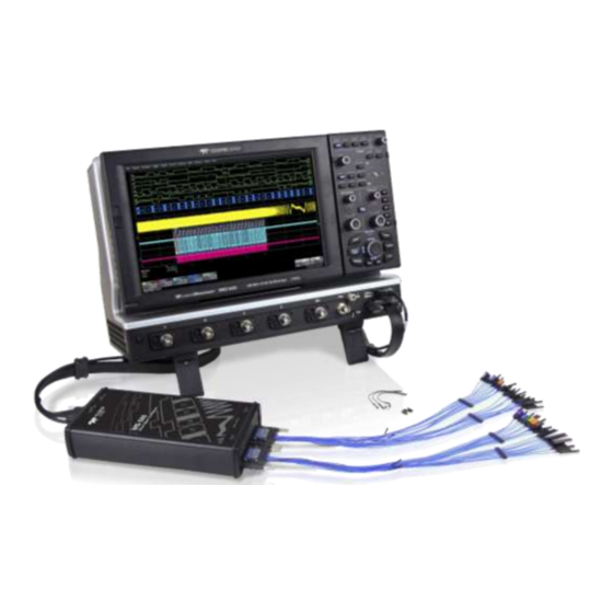
Operator's Manual Contents Introduction ......................1 Technical Overview ....................... 2 Standard Hardware ....................... 3 Accessories ........................5 Connecting the Mixed Signal Device ..............7 Connecting to the Oscilloscope ................... 7 Digital Connections ..................... 10 Digital Setup ...................... 11 Digital Logic Setup ...................... 11 Digital Group Setup ..................... - Page 4 Thank you for purchasing a Teledyne LeCroy MS-500 Mixed Signal Oscilloscope Option. The MS-500 is a powerful solution for the challenge of measuring multiple, mixed signals in a single oscilloscope. An enhancement to Teledyne LeCroy oscilloscopes, the MS-500 extends their testing range by adding 18 or 36 digital channels for display or triggering.
-
Page 5: Introduction
The MS-500 and MS-500-36 are identical except the MS-500-36 standard configuration is for 36 channels. The MS-500-36 can be operated in 36 or 18 channel mode for higher performance. The MS-500 is configured as an 18 channel instrument and can be upgraded with an additional lead set to support 36 channels. -
Page 6: Technical Overview
100 mV. The indeterminate range of 50 mV around the threshold voltage level is the level below which the MS-500 will not operate. However, the MS-500 can support a signal as low as 100 mV only if the input signal’s quality is adequate. -
Page 7: Standard Hardware
The USB2.0 cable provides downloading of trigger conditions from the oscilloscope to the MS-500 and uploading of digital data from the MS-500 to the oscilloscope. Standard Hardware The MS-500 is delivered with the following hardware:... - Page 8 MS-500 Mixed Signal Oscilloscope Option Part Description MS-500 (MS-500-36) Bus Cable 1.3m cable to connect Mixed Signal Accessory to the main oscilloscope unit, includes USB2.0 cable. This connection provides timebase synchronization, cross-triggering and power. 3" Flexible Lead for grounding individual digital inputs...
-
Page 9: Accessories
D0-D17 or D0-D35. This can be useful if you MSO-DLS-36 have more than one device under test and don't wish to disconnect/reconnect leads. MSO-DLS-36 available for MS-500-36 only. Large Gripper PK400-1 Large gripper probe set for 0.10 inch Probe Set (2.54 mm) pin pitch. - Page 10 MS-500 Mixed Signal Oscilloscope Option Accessory Part Number Description Small Gripper PK400-3 Small gripper probe set for 0.008 inch Probe Set (0.2 mm) pin pitch. Includes 10 probes with color-coded leads. Mictor Cable MSO-MICTOR Mictor Connection cable, 16" (40.64 cm),...
-
Page 11: Connecting The Mixed Signal Device
Operator's Manual Connecting the Mixed Signal Device Connecting to the Oscilloscope To connect the Mixed Signal accessory to your oscilloscope: 1. Connect the Bus Cable to the L connector on the oscilloscope. Be sure the head is turned so that the positioning wedge fits into the groove at the top of the connector. - Page 12 MS-500 Mixed Signal Oscilloscope Option Connect the other end of the Bus Cable to the MS-500. Again, be sure to align the wedge and the groove. Fasten the thumb screws. Connect the other end of the USB 2.0 Cable to the MS-500.
- Page 13 Operator's Manual 5. Connect the Digital Leadset to the Digital Inputs D0 – D17 connector on the opposite end of the MS-500 and fasten the thumb screws. For MS-500-36 repeat this step with the leadset labeled D18 – D35. NOTE: Each digital line has a ground connection for optimal performance.
-
Page 14: Digital Connections
The standard terminations on the digital leadset can be pushed directly onto 25-mil pins. MicroGrippers or NanoGrippers may also be used to probe the test circuit’s pins. Teledyne LeCroy provides a selection of small, medium, and large grippers for various pitch sizes. A more complete selection of adapter probes is available for most chips from Emulation Technology Inc., Yamaichi Inc., and other manufacturers. -
Page 15: Digital Setup
Operator's Manual Digital Setup Digital Logic Setup Each lead bank requires a Logic Setup to determine the assignment of a 1 or 0, depending on the measured voltage relative to the Threshold. Threshold Level The threshold level determines how the input signal is interpreted. Input voltages less than the threshold are converted to 0, while input voltages greater than the threshold are converted to 1. - Page 16 The minimum signal swing is 100 mV. The indeterminate range of 50 mV around the threshold voltage level is the level below which the MS-500 will not operate. However, the MS-500 can support a signal as low as 100 mV only if the input signal’s quality is adequate.
-
Page 17: Digital Group Setup
NOTE: Along the bottom of the dialog is an indicator for each line in all the lead banks. On MS-500 options, all 36 possible lines are shown, even if only D0-D18 are available. As add lines to the group, the indicator is checked, so you can always see all the lines currently in the group. -
Page 18: Displaying Digital Traces
MS-500 Mixed Signal Oscilloscope Option Displaying Digital Traces The Trace On checkbox is selected by default, so if you are connected to a live input, you should see digital traces appear as you add lines to the group. To turn off the trace display, clear Trace On. -
Page 19: Renaming Digital Lines
Operator's Manual Digital line traces 1 division high starting at position 4 (top of grid). Digital bus trace 1 division high starting at position 4. Store Display To store the entire group and display setup to an internal memory, touch the Store button at the far right of the dialog. -
Page 20: Digital Triggering
MS-500 Mixed Signal Oscilloscope Option Digital Triggering Setting Up Digital Triggers To access the Trigger setup dialogs, do one of the following: Choose Trigger > Trigger Setup from the menu bar • • Press the front panel Trigger Setup button Touch the Trigger descriptor box •... -
Page 21: Pattern Trigger
Operator's Manual Pattern Trigger Pattern is the default trigger when the Mixed Signal option is connected to the oscilloscope, as these users generally wish to find and trigger upon digital logic patterns. However, a Pattern trigger can also be set on a user-defined pattern of High or Low voltage levels in analog channels (including the External Trigger input), or a combination of digital and analog patterns when Mixed Signal capabilities are available. - Page 22 MS-500 Mixed Signal Oscilloscope Option To apply a digital logic pattern, either: Enter the hexadecimal value of the pattern (in Hex or Value). • Lines will take a logical 1, 0, or X ("Don't Care") according to the pattern. Disabled lines will remain X.
- Page 23 Operator's Manual Analog Pattern 1. To add the analog pattern to the digital pattern, leave your digital pattern as is and skip to step 2. To create an analog-only pattern, touch Set All To... and select Don't Care. This will eliminate any meaningful digital pattern and activate all the Boolean operators.
-
Page 24: Edge Trigger
MS-500 Mixed Signal Oscilloscope Option Edge Trigger Edge triggers upon a achieving a certain voltage level in the positive or negative slope of the waveform. It is the default trigger selection on standard oscilloscopes. On the Trigger dialog, select Edge trigger type to display the controls. -
Page 25: Width Trigger
Operator's Manual Width Trigger Width triggers upon finding a positive- or negative-going pulse width when measured at the specified voltage level. On the Trigger dialog, select Width trigger type to display the controls. 1. Choose the Source input line. 2. Choose the line Polarity on which to trigger. 3. -
Page 26: Glitch Trigger
MS-500 Mixed Signal Oscilloscope Option Glitch Trigger Glitch triggers upon finding a fixed pulse-width time or time range. On the Trigger dialog, select Smart trigger type, then Glitch to display the controls. 1. Choose the Source input line. 2. Choose the Polarity on which to trigger. -
Page 27: Interval Trigger
Operator's Manual Interval Trigger Interval triggers upon finding a specific interval, the time (period) between two consecutive edges of the same polarity: positive to positive or negative to negative. Use the interval trigger to capture intervals that fall short of, or exceed, a specified range. On the Trigger dialog, select Smart trigger type, then Interval to display the controls. -
Page 28: Dropout Trigger
MS-500 Mixed Signal Oscilloscope Option Dropout Trigger Dropout triggers when a signal loss is detected. The trigger is generated at the end of the timeout period following the last edge transition that meets the trigger conditions. It is used primarily in single-shot applications with a pre-trigger delay. -
Page 29: Qualified Trigger
Operator's Manual Qualified Trigger Qualified arms the trigger on the A event, then fires on the B event. In Normal trigger mode, it automatically resets after the B event. The options for the B event depend on the type of A event. You may apply additional Holdoff by time or number of events. -
Page 30: Reference
MS-500 Mixed Signal Oscilloscope Option Reference Returning a Product for Service Contact your local Teledyne LeCroy service center for annual factory calibration or other service. If the product cannot be serviced on location, the service center will give you a Return Material Authorization (RMA) code and instruct you where to ship the product.