Table of Contents
Advertisement
Quick Links
Advertisement
Chapters
Table of Contents
Troubleshooting

Related Manuals for Ricoh BRG-P1w


Summary of Contents for Ricoh BRG-P1w
- Page 1 Model BRG-P1w Machine Code: J034 Field Service Manual 8 January, 2013...
-
Page 3: Responsibilities Of The Customer Engineer
Safety Instructions, Conventions For your safety, please read this manual carefully before you service the machine. Always keep this manual handy for future reference. Safety Information Always obey these safety precautions when using this product. Switches and Symbols Where symbols are used on or near switches on machines for Europe and other areas, the meaning of each symbol conforms with IEC60417. -
Page 4: Before Installation, Maintenance
Before Installation, Maintenance Shipping and Moving the Machine • Work carefully when lifting or moving the machine. If the machine is heavy, two or more customer engineers may be required to move the machine without causing injury (muscle strains, spinal injuries, etc.) or damage to the machine if it is dropped or tipped over. -
Page 5: Special Tools
• Never use your fingers to check moving parts that are causing spurious noise. Never use your fingers to lubricate moving parts while the machine is operating. Special Tools • Use only standard tools approved for machine maintenance. • For special adjustments, use only the special tools and lubricants described in the service manual. Using tools incorrectly, or using tools that could damage parts, could damage the machine or cause injuries. -
Page 6: Organic Cleaners
Organic Cleaners • During cleaning never use any organic cleaners (alcohol, etc.) other than those described in the service manual. • Make sure the room is well ventilated before using any organic cleaner. Always use organic solvents in small amounts to avoid breathing the fumes and becoming nauseous. •... -
Page 7: After Installation Servicing
After Installation Servicing Disposal of Used Items • Ink is flammable. Never attempt to incinerate empty ink cartridges. • Always dispose of used items in accordance with the local laws and regulations regarding the disposal of such items. • To protect the environment, never dispose of this product or any kind of waste from consumables at a household waste collection point. -
Page 8: Safety Instructions For Ink Cartridges
Safety Instructions for Ink Cartridges Accidental Exposure To Ink • If ink gets on the skin, wash the affected area immediately with soap and cold running water. • If ink gets into the eyes, immediately flush the eyes with cold running water. If there are signs of irritation or other problems, seek medical attention. -
Page 9: Conventions Used In This Manual
• Replacing a lithium battery with any type other than the one prescribed for use on the board could lead to an explosion or damage to the PCB. • Never discard used batteries by mixing them with other trash. • Remove used batteries from the work site and dispose of them in accordance with local laws and regulations regarding the disposal of such items. -
Page 10: Machine Name
Throughout this service manual, "SEF" denotes "Short Edge Feed" and "LEF" denotes "Long Edge Feed". Machine Name Printer Name Model No. BRG-P1w J034 • The J034 is equipped with the ZICO controller. • The NIC is mounted on the CTL board. -
Page 11: Trademarks
Trademarks ® ® ® • Microsoft , Windows , and MS-DOS are registered trademarks of Microsoft Corporation in the United States and /or other countries. ® • PostScript is a registered trademark of Adobe Systems, Incorporated. ® • PCL is a registered trademark of Hewlett-Packard Company. ®... -
Page 12: Table Of Contents
TABLE OF CONTENTS Safety Instructions, Conventions........................1 Responsibilities of the Customer Engineer....................1 Before Installation, Maintenance........................2 Shipping and Moving the Machine.....................2 Power..............................2 Installation, Disassembly, and Adjustments..................2 Special Tools............................3 During Maintenance............................3 General..............................3 Safety Devices............................3 Organic Cleaners..........................4 Power Plug and Power Cord........................4 After Installation Servicing..........................5 Disposal of Used Items..........................5 Points to Confirm with Operators......................5 Safety Instructions for Ink Cartridges......................6... - Page 13 Main Machine.............................21 Front View............................21 Left View...............................22 Rear View.............................22 Options.................................23 External Options: J034........................23 Guidance for Differences between J034 and that of the base machine.............24 Ink Tube Stay..............................24 Paper Transport Belt Unit..........................24 Rollers................................24 The Paper Feed Roller.........................25 The Connecting Roller.........................25 2. Installation Preparation...............................27 Environment..............................27 Choosing a Location............................27...
- Page 14 4. Replacement and Adjustment Before Replacing Parts.............................45 Removal Table.............................45 Required Tools.............................47 Common Procedures............................48 Simple Removals............................48 Duplex Unit............................48 Ink Collector Unit..........................49 Covers................................50 Cover Names............................50 Order of Removal Cover........................51 Rear Cover, Top Cover........................51 Right Front Cover..........................53 Right Cover............................54 Port Cover............................56 Left Cover.............................56 Canopy Cover.............................57 Front Cover, Operation Panel Board....................57 Re-assembly............................59...
- Page 15 After Replacement..........................83 Motors................................86 Horizontal Motor............................86 Vertical Motor..............................88 Fan................................91 Clutches................................93 Feed Clutch..............................93 Transport Belt..............................96 Transport Belt, Charge Roller, Pressure Plate, Pressure Rollers..............96 Sensors, Switches............................101 Vertical Encoder Sensor..........................101 Ink Level Sensor............................102 1st Registration Sensor..........................104 2nd Registration Sensor..........................107 Air Purge Detection Switch........................108 Top Cover Switch............................110 Right Front Cover Switch...........................111 Temperature/Humidity Sensor.........................113 Trailing Edge Sensor..........................114...
- Page 16 Preparing for Test Printing.........................138 Nozzle Check............................138 Nozzle Check Pattern........................138 Color Demo Print............................139 Print Head Cleaning..........................140 Print Head Flushing............................141 Adjust Paper Feed.............................141 Head Position.............................143 Registration..............................144 Cleaning.................................146 Maintenance Unit Cleaning........................146 Connecting Rollers Cleaning........................147 Transport Belt Cleaning..........................148 Friction Pad Cleaning..........................150 Horizontal Encoder Strip Cleaning......................151 Cleaning procedure.........................151 Horizontal Encoder Sensor Cleaning (TBA)...................153 Vertical Encoder Wheel Cleaning......................154...
- Page 17 Input Check: Sensors........................164 Input Check: Sensors........................165 Input Check: Temperature and Humidity..................165 Input Check: Air..........................166 Input Check: Ink Cartridge Set Sensors..................166 Input Check: Ink Cartridge Levels....................167 Print an Engine Maintenance Summary..................167 SP7-XXX..............................167 Display Count: Machine Total......................167 Display Count: User Cleaning......................168 Display Count: User Flushing......................168 Date Display SC Log........................168 Display Total Count: SC Log......................169 Display Jam Log..........................169...
- Page 18 Operation Panel Messages........................200 Service Call Conditions..........................206 SC code display patterns and how to clear them................206 Service Call Code Tables.........................207 Jam Codes..............................224 Jam Codes............................224 Jammed paper location........................233 Status Monitor Messages.........................234 7. Energy Saving Energy Save..............................239 Energy Saver Modes..........................239 Timer Settings............................239 Return to Standby Mode........................239 Recommendation..........................240 Paper Save..............................241 Effectiveness of Duplex/Combine Function....................241...
-
Page 19: Product Information
1. Product Information Specifications See "Appendices" for the following information: • Printer Engine • Supported Paper Sizes • Control Boards... -
Page 20: Overview
1. Product Information Overview Before You Begin... What This Manual Contains This Service Manual covers J034 model of this printer series. This is a brief summary of the differences between J034 and that of base machine J028. J028 The NIC is mounted on the CTL board. This model is PCL compatible. -
Page 21: Printer Models And Options
Yes (J314) *1 The NIC is mounted on the CTL board of the J028/J034. Printer Models and Options This manual describes the following printer model and options. Name Ricoh Name J034 BRG-P1w Aficio SG 7100DN(SG 7100DN) J314 Paper Feed Unit... -
Page 22: Print Cartridges
1. Product Information Print Cartridges The following print cartridges can be used with the J034. Name Comments Starter Ink Cartridge (K)* These are the starter cartridges shipped with the Starter Ink Cartridge (C) * machine. These are used to initialize ink supply when Starter Ink Cartridge (M) * the machine is installed and then discarded. -
Page 23: Main Machine
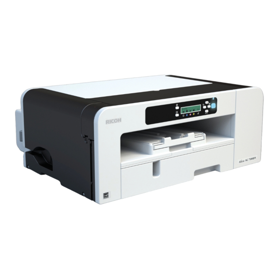
Overview Main Machine Front View 1. Top cover Open to see inside the printer if a jam occurs. 2. Operation panel Operation keys and the 2-line LCD. The operation panel can be raised and set in the upright position if the printer is placed at a height where it is difficult to reach. 3. -
Page 24: Left View
1. Product Information Left View A: Ethernet port The port for the ethernet cable. The NIC is mounted on the controller board. B: USB port This is the connection point for the USB cable from the PC. C: Power inlet The connection point for the power cord. -
Page 25: Options
Overview 3. Bypass tray connection point This is the connection point for an optional multi bypass tray. Options External Options: J034 The Paper Feed Unit TK1190 (J314) [A] is used with the J034 only. Only one paper feed units can be installed. -
Page 26: Guidance For Differences Between J034 And That Of The Base Machine
1. Product Information Guidance for Differences between J034 and that of the base machine Ink Tube Stay The J034 model adds the ink tube support stay [A] between the carriage and the ink supply unit so that the large size papers can be printed smoothly. However, this stay requires no additional steps for the replacement. -
Page 27: The Paper Feed Roller
Guidance for Differences between J034 and that of the base machine The Paper Feed Roller • The two e-rings should be released to remove the pressure rollers that pinch the paper feed roller p.123). The Connecting Roller • The ink level sensor should be removed to pull out the right side of the connecting roller shaft ( 126 "Connecting Rollers") from the main machine. - Page 28 1. Product Information...
-
Page 29: Installation
2. Installation Preparation Environment • White area: Permissible Range • Blue area: Recommended Range Set up the machine in a location that meets these minimum requirements: Temperature Range: 10°C to 32°C (50°F to 89.6°F) Humidity Range: 15% to 80% RH Ambient Illumination: Less than 2,000 Lux (never expose to direct sunlight). - Page 30 2. Installation • Extreme changes from low to high temperature or high to low temperature. • Cold or cool air directly from an air conditioner. • Heat from a space heater. 3. Never install the machine in areas near: • Dust, lint, or corrosive fumes. •...
-
Page 31: Minimum Space Requirements
Preparation Minimum Space Requirements At least 26 cm (10.3 inches) At least 3 cm (1.2 inches) At least 45 cm (17.8 inches) At least 10 cm (4.0 inches) e*1. At least 13 cm (5.2 inches) *1 A clearance of 30 cm (11.9 inches) is necessary if the multi bypass tray is attached. Power Source J034 North America... -
Page 32: Using The Operation Panel
2. Installation Using the Operation Panel Here is a brief description of how to use the keys on the printer operation panel. This information is provided as a quick summary of important information described in the Operating Instructions. Key Summary Table Key/Indicator What It Does Power... - Page 33 Using the Operation Panel Key/Indicator What It Does [ ], [ /Menu]: Increase or decrease values on the display when making settings. /Menu [ /Menu]: When the printer is in standby mode, press [ /Menu] key to enter the user menu. Cartridge Show the ink levels of the print cartridges.
-
Page 34: Printer Display Summary
2. Installation Printer Display Summary Operation Panel: Cartridge replacement indicator The printer shows a multi-level dynamic display that keeps the operator informed about the status of the ink levels in the tanks. The example below for Black (K) shows the progression in the display from full on the left to completely empty on the right. -
Page 35: Operation Panel: Waste Ink Full Indicator
Using the Operation Panel The operator can continue printing by pressing [Form Feed] on the operation panel. The printer will continue to print until the print head ink tank is empty. However, in this operation mode the machine cannot perform print head maintenance. Operation Panel: Waste Ink Full Indicator The amount of waste ink in the ink collector unit is indicated on a six-step scale, namely 0, 20, 40, 60, 80, and 100%. -
Page 36: User Menu Mode
2. Installation User Menu Mode Menu/Menu Item Function Counter Displays or prints the number of pages printed in B&W, full color, and Economy Color. Note: Changing Bit SW 5 modifies the display: • Setting Bit SW 5-6 to "0" switches the Economy Color display off. •... - Page 37 Using the Operation Panel Menu/Menu Item Function Config.Page(*) Prints information that tells you the current configuration of the printer. • System Reference. Lists printer version, attached options, name of print language, amount of ink remaining for each ink cartridge. • Paper Input. Lists the specified Tray Priority setting and the Paper Input menu settings.
- Page 38 2. Installation Menu/Menu Item Function Dry-delay (Exit) To prevent spoiling of printed copies, select a print delivery interval to allow them to dry. The interval must be long enough to allow a sheet to dry. You can specify an interval between 1 and 20 seconds. Default: [Off] Dry-delay (Dup) Pauses printing to allow first side of duplex print to dry before printing second side of same page.
- Page 39 Using the Operation Panel Menu/Menu Item Function Memory Usage Frame Priority, Font Priority Unit of Measure Determines the units of measure ("mm" or "in.") Default: mm Page Size Allows selection of page size. Paper Type Plain Paper, IJ Plain Paper, Glossy Paper, Thick Paper, Postcard, Inkjet Postcard, Envelope Preprinted Ppr.
- Page 40 2. Installation Menu/Menu Item Function Network Setup Use to do the network settings. Setting Default Machine Name Display only Host Name Display only Domain Name Display only IPv4 DNS ServerAddress 1 and 2 0.0.0.0 IPv4 DDNS DHCP IPv4 Address 11.22.33.44 Pv4 Subnet M 0.0.0.0 Network Setup Pv4 Gatewy.
-
Page 41: Access To Menus During An Error
Using the Operation Panel Menu/Menu Item Function Network Setup IPsec MAC Address Display only Ethernet Speed Auto Select Prmt SNMPv3 Com Cleartext Pmt SSL/TLS Com IPv4: Active IPv6: Active Restore Default USB Setting Two settings are available: • USB Speed. •... - Page 42 2. Installation • List/Test Print. No selections are available. Even without computers, you can specify settings, such as the time and date, on the machine's control panel. • Menus could not be accessed while the printer is busy.
-
Page 43: Installation
Installation Installation These machines and all peripherals are installed by the customer. The installation procedures are described in the operating instruction manuals issued to the customer with purchase of the main machine or peripheral unit. -
Page 44: Important Information
2. Installation Important Information Make sure that the customers understand the following points about moving, storing, and using the printer. Checklist Before Moving the Printer 1. Turn the printer off. Disconnect the power cord. • Never disconnect the power cord without first turning off the printer. 2. -
Page 45: Preventive Maintenance
3. Preventive Maintenance PM Table There are no PM Parts in this machine. Service Call Procedures The procedures listed below should be done by the service technician. For more details about how to do these procedures, please refer to "Cleaning Procedures". Description At Service Call, or As Required External Covers... - Page 46 3. Preventive Maintenance...
-
Page 47: Replacement And Adjustment
4. Replacement and Adjustment Before Replacing Parts Removal Table The swap-and-repair system is used for this printer. The table below lists the level of difficulty for replacement of each item. Level 1: No Tools Required Component Comments Duplex Unit Standard. Back of machine End Fence Inside paper cassette Ink Cartridge... - Page 48 4. Replacement and Adjustment Component Difficulty: Low, Medium, High Front Cover High Voltage Power Supply (HVPS) Maintenance Unit OPU (Operation Panel Unit) Vertical Encoder Sensor Vertical Encoder Wheel Vertical Motor Controller Board Medium Cooling Fan Medium Right Ink Sump Medium 2nd Registration Sensor High Carriage Unit...
-
Page 49: Required Tools
Before Replacing Parts Level 3: Require precision adjustment at factory (Not Replaced in this Field) Component Comments None Required Tools This is a list of tools needed to service the machines. These tools are used to keep the print heads from drying out during long periods of storage following machine repair. -
Page 50: Common Procedures
4. Replacement and Adjustment Common Procedures Simple Removals Duplex Unit 1. Push and hold the left and right release tabs [A] together to unlock the duplex unit [B]. 2. Pull the duplex unit out of the machine. Reinstallation • The duplex unit must be installed in the machine at all times. The machine will not operate without the duplex unit installed. -
Page 51: Ink Collector Unit
Common Procedures Ink Collector Unit Before you begin: Never remove the ink collector unit unless it requires replacement. A message will appear and tell you that the ink collector unit needs to be replaced. • You will need a self-sealing plastic bag to hold the ink collector unit. •... -
Page 52: Covers
4. Replacement and Adjustment 5. Push in the ink collector [B] until you hear it snap and lock in place. 6. Close the right front cover. • The ink collector unit has an internal ID chip that automatically resets the counter for the ink collector unit. -
Page 53: Order Of Removal Cover
Common Procedures Paper Cassette Rear Cover Duplex Unit Right Cover Left Cover Port Cover * No screws, tabs only. *1 This picture is a shot that is taken with the port cover opened because of the easily view. Order of Removal Cover It is very important that you understand how to remove and reinstall the covers before doing replacement procedures. - Page 54 4. Replacement and Adjustment Raise the top cover [A]. 3 screws ( x 3).
-
Page 55: Right Front Cover
Common Procedures Press the tabs [A] on the top left and top right of the rear cover to detach the top of the rear cover. Slide the rear cover up to detach its bottom. Disengage the top cover latch [A]. Right Front Cover... -
Page 56: Right Cover
4. Replacement and Adjustment Open the right front cover [A]. Disengage the latch. Remove the right front cover. Right Cover Preparation • Duplex unit ( p.48) • Right front cover (See above) - Page 57 Common Procedures Raise the top cover [A]. 2 screws ( x 2). Pressing the tab [A] on the rear cover, lift the right cover [B] to detach it.
-
Page 58: Port Cover
4. Replacement and Adjustment Port Cover Pressing the tab [A], detach the port cover [B]. When you detach the left cover, detach the port cover in advance. Left Cover Preparation • Duplex unit ( p.48) • Port cover (See above) •... -
Page 59: Canopy Cover
Common Procedures 2 screws ( x2). Holding the cover's center bottom [A], lift the cover [B] to detach it. Canopy Cover Preparation • Duplex unit ( p.48) • Rear cover ( p.51 "Rear Cover, Top Cover") • Top cover ( p.51 "Rear Cover, Top Cover") •... - Page 60 4. Replacement and Adjustment Open the right front cover. Remove the ink cartridges. Remove the screws ( x2). The operation panel board [A] is located behind the front cover.
-
Page 61: Re-Assembly
Common Procedures Release the clip fastening the flexible flat cable (FFC) and detach the cable from the board. Slide the front cover [A] to the left to detach it. Release the tabs and detach the operation panel board [A] ( x1). - Page 62 4. Replacement and Adjustment Operation Panel Make sure that the blue band of the FFC edge connector [A] is facing up. • The blue band must be facing up when you reconnect the FFC to the operation FFC connector. • If the FFC is twisted and connected with the blue band facing down, the printer will not operate.
- Page 63 Common Procedures Right Cover Check that the harness and ink tube are secured. • Be sure to secure the harness with the tabs (at five points). • Be sure to secure the ink tube with the tabs (at three points).
- Page 64 4. Replacement and Adjustment Check the maintenance unit [A]. • If the triangles are not aligned as shown above, this means the print head is locked and ready for operation. You can re-attach the right cover. • If the triangles are aligned tip-to-tip as shown at [A], this means the carrier is unlocked (not ready for operation) and can be moved manually.
- Page 65 Common Procedures Check the connection with the front cover. • As shown above, slide the right cover along the guide rail on the front cover to attach it. • Align the slit on the right cover with the projected part [A] on the machine's frame to secure the cover.
-
Page 66: Unlocking, Moving The Carriage
4. Replacement and Adjustment Rear Cover Engage the tabs on the rear cover in the brim of the machine's frame and attach the rear cover. After attaching the rear cover, check that the tabs [A] on the top left and top right are engaged. - Page 67 Common Procedures 1. The right cover ( p.54) 2. Look at the maintenance unit [A] and locate the two triangles. 3. Insert the tip of a screwdriver into the hole [B] and turn it counter-clockwise to rotate the lower triangle up to the other triangle [C] until they are aligned. 4.
-
Page 68: Maintenance Unit, Right Ink Sump
4. Replacement and Adjustment Maintenance Unit, Right Ink Sump Maintenance Unit Preparation • Duplex unit ( p.48) • Top Cover ( p.51 "Rear Cover, Top Cover") • Canopy Cover ( p.57) • Right Cover ( p.54) • Spread several sheets of thick paper (not cloth) where you can set the unit after it has been removed. - Page 69 Maintenance Unit, Right Ink Sump 2. Open the right front cover and pull out the ink collector [A] about half-way (You do not need to remove it.). 3. Remove screws of maintenance unit [A] ( x 2). 4. Disconnect maintenance unit sensor [A] ( x 1).
- Page 70 4. Replacement and Adjustment 5. Release the lock [A], and then remove the injector. 6. Pull the maintenance unit and injector out of the printer and lay them on some paper. • Handle the maintenance unit carefully. • The bottom of the unit is covered with ink. Place it on a piece of clean paper (not cloth). •...
-
Page 71: Right Ink Sump
Maintenance Unit, Right Ink Sump 1. Re-install the top of the maintenance unit [A] first. 2. Check the tubing [B] between the needle and the bottom of the maintenance unit. 3. Make sure that the line on the tube is straight and not bent. This confirms that the tubing is not twisted. - Page 72 4. Replacement and Adjustment 1. The right ink sump [A] is located below and to the left of the maintenance unit (shown removed in the photo above.) 2. 1 screw ( x 1) 3. Pull the right ink sump aside to expose the ink tubes, and then remove the right ink sump using its handles.
-
Page 73: Encoders
Encoders Encoders Vertical Encoder Wheel Preparation • Duplex unit ( p.48) • Canopy cover ( p.57) • Rear cover ( p.51 "Rear Cover, Top Cover") • Top cover ( p.51 "Rear Cover, Top Cover") • Left cover ( p.56) 1. Remove screw ( x1). - Page 74 4. Replacement and Adjustment 3. The tension spring [A] ( x1). 4. Use a pair of needle-nose pliers to remove C-clip [A] ( x1). 5. Carefully insert the tip of a long, thin screwdriver behind the drive wheel. 6. Nudge the wheel slight to the front and remove the wheel with the vertical encoder attached. 7.
-
Page 75: Horizontal Encoder Strip
Encoders Reinstallation • When reinstalling the vertical encoder wheel [A], turn the wheel slowly while pressing in slightly until it snaps into the correct position. • After attaching the timing belt, move the belt by hand to check that the wheel rotates smoothly. Horizontal Encoder Strip Preparation •... - Page 76 4. Replacement and Adjustment 2. Insert the driver [B] in [A] between the guide rail and carriage, and then lift the carriage unit. This is necessary for engaging the horizontal encoder strip into the sensor's recess without making contact. 3. On the right, pull the right end of the encoder strip [A] and disconnect it. •...
-
Page 77: Reinstallation
Encoders 4. On the left, disconnect the left end of the strip [A]. • If the sensor for reading the horizontal encoder strip is stained, clean the sensor when you replace the strip. Reinstallation • If you have removed the strip or if you are replacing the strip with a new one: •... - Page 78 4. Replacement and Adjustment 2. First, hook the strip's left end to the tab. 3. Next, stretch to straighten the strip and hook the strip's right end to the tab. • Make sure the black triangle is facing up. • You must re-attach the extension bracket [A].
- Page 79 Encoders 4. Pull out the driver [A], and then place the carriage back to its original position. Make sure that the horizontal encoder strip is engaged in the sensor's recess [B].
-
Page 80: Boards
4. Replacement and Adjustment Boards • Always replace a PSU with the PSU designed for the machine. Preparation • Duplex unit ( p.48) • All covers ( p.50) • Fan, Fan bracket ( p.91 "Fan") 1. The PSU [A] is on the left front corner of the printer. 2. -
Page 81: Hvps
Boards • 100V : For NA • 200V : For EU, Aaia HVPS Preparation • Duplex unit ( p.48) • Canopy cover ( p.57) • Top cover ( p.51 "Rear Cover, Top Cover") • Rear Cover ( p.51) • Left Cover ( p.56) •... -
Page 82: Printer Engine Ctl Board
4. Replacement and Adjustment 2. Remove the HVPS from its cover ( x 2, x 1, bayonet x 1). Printer Engine CTL Board Before Replacement Before replacing the control board you should always print Service Summary and an Engine Summary Chart. -
Page 83: Ctl Board Replacement
Boards Do SP5-990-002 (Print SMC). (Printing requires about 2 minutes.) 1. Confirm that paper is loaded in the paper tray. 2. Enter the Service Menu. SYSTEM Ver. nnn Service Menu 3. [ /Menu]> "Engine Main."> [#Enter]. SP No. 5990002 4. Using [ ] or [ /Menu], enter "5990002". - Page 84 4. Replacement and Adjustment 1. The CTL board cover ( x 3, x 2, x 1). • Slide the cover, and then remove it. Make sure that the carriage is in the home position. Otherwise, the cover is blocked by the carriage. 2.
-
Page 85: After Replacement
Boards After Replacement After replacing the CLT board, you need to specify the serial number, PnP code, and destination, and then initialize the VMRAM. Be sure to perform this in the order of (1) specifying the serial number, (2) specifying the PnP code and destination, and (3) initializing the VMRAM. (1) Serial number Switch the machine on. - Page 86 4. Replacement and Adjustment Ricoh LANIER SAVIN Select the PnP code.> [#Enter]> [Escape]> [Escape]. SP No. 5807001 Enter "5807001"> [#Enter]. Japan Select the destination> [#Enter]> [Escape]. Exit the SP mode. (3) Initializing the NVRAM Enter the SP mode. Select "Engine Maint."> [#Enter].
- Page 87 Mar. Time The Number of Times the Final (4 Summer Time Finished or 5) Time to Finish the Summer Time 2:00 AM 1:00 AM 0:00 AM PnP code Settings Ricoh LANIER SAVIN Spec. Value Spec. Spec. Value Value Spec. Value...
-
Page 88: Motors
4. Replacement and Adjustment Motors Horizontal Motor Preparation • Duplex unit ( p.48) • Top cover ( p.51 "Rear Cover, Top Cover") • Canopy cover ( p.57) • Rear cover ( p.51 "Rear Cover, Top Cover") • Left cover ( p.56) •... - Page 89 Motors 2. Remove the screws at the right end ( x 2). 3. Remove the screw at the left end, loosen the belt's tension, and then remove the spring. ( x 1, x 1) 4. Remove the timing belt on the right end.
-
Page 90: Vertical Motor
4. Replacement and Adjustment 5. The horizontal motor ( x 1). Vertical Motor Preparation • Duplex unit ( p.48) • Rear cover ( p.51 "Rear Cover, Top Cover") • Top cover ( p.51 "Rear Cover, Top Cover") • Canopy cover ( p.57) •... - Page 91 Motors 2. Unhook the harness holder [A], and then lift it while sliding it to the right. Make sure to expose the screw holes. 3. Open the AC inlet's bracket as shown ( x 3, grounding screw x 1).
- Page 92 4. Replacement and Adjustment 4. Remove the vertical motor [A] from the AC bracket [B] ( x 1, x 1, x 2). Re-installation (when the motor bracket is removed.): When you attach the parts, attach the motor bracket afterward. 1. As shown, slide the right bottom part in, and then slide the left top part in.
-
Page 93: Fan
Motors 2. After sliding the motor bracket in, slowly adjust the motor position to align the screw holes, and then reassemble the parts. Preparation • Duplex unit ( p.48) • All covers ( p.50) 1. Pressing the tab [A], remove the fan from its bracket ( x 1). - Page 94 4. Replacement and Adjustment...
-
Page 95: Clutches
Clutches Clutches Feed Clutch Preparation • Duplex unit ( p.48) • Vertical encoder wheel ( p.71) • Top cover ( p.51 "Rear Cover, Top Cover") • Canopy cover ( p.57) • Rear cover ( p.51 "Rear Cover, Top Cover") • Left cover ( p.56) 1. - Page 96 4. Replacement and Adjustment • If the connector cannot be removed because it is behind the AC bracket, open the AC bracket. 3. Remove the feed clutch ( x 1). Re-installation...
- Page 97 Clutches 1. Fasten the clutch with the machine's protruding part positioned between the clutch guides.
-
Page 98: Transport Belt
4. Replacement and Adjustment Transport Belt Transport Belt, Charge Roller, Pressure Plate, Pressure Rollers Preparation • Duplex unit ( p.48) • Rear cover ( p.51 "Rear Cover, Top Cover") • Top cover ( p.51 "Rear Cover, Top Cover") • Canopy cover ( p.57) •... - Page 99 Transport Belt 2. Take out the charge roller and the cover ( x 1). 3. Pull the pressure plate [A] out to remove it ( x 4, x 6).
- Page 100 4. Replacement and Adjustment 4. The transport belt screws ( x 2). 5. The harness holders ( x 3, x 1).
- Page 101 Transport Belt 6. Remove the exit guide [A] from the main machine ( x 2). 7. The timing belt [B] ( x 1).
- Page 102 4. Replacement and Adjustment 8. The transport belt [A].
-
Page 103: Sensors, Switches
Sensors, Switches Sensors, Switches Vertical Encoder Sensor Preparation • Duplex unit ( p.48) • Top cover ( p.51 "Rear Cover, Top Cover") • Rear cover ( p.51 "Rear Cover, Top Cover") • Left cover ( p.56) • Canopy cover ( p.57) •... -
Page 104: Ink Level Sensor
4. Replacement and Adjustment Ink Level Sensor Preparation • Duplex unit ( p.48) • Rear cover ( p.51 "Rear Cover, Top Cover") • Top cover ( p.51 "Rear Cover, Top Cover") • Right cover ( p.54) • Maintenance unit ( p.66) •... - Page 105 Sensors, Switches 2. Remove the spring [A], and then remove the air release lever [B] ( x 2). 3. Remove the clamps holding the ink tubes, remove the connector, and then move the ink tubes aside to expose the screw holes ( x 1, x 3).
-
Page 106: 1St Registration Sensor
4. Replacement and Adjustment 4. Remove the screws ( x2). 5. Remove the ink level sensor ( x3). 1st Registration Sensor Preparation... - Page 107 Sensors, Switches • Duplex unit ( p.48) • Rear cover ( p.51 "Rear Cover, Top Cover") • Top cover ( p.51 "Rear Cover, Top Cover") • Right cover ( p.54) • Left cover ( p.56) • Canopy cover ( p.57) •...
- Page 108 4. Replacement and Adjustment 4. Disconnect the ink tubes. Before you disconnect the ink tubes, squeeze their connecting parts with fingers or radio pliers to empty their contents into the print head tanks, so as to prevent the ink from dropping. 5.
-
Page 109: 2Nd Registration Sensor
Sensors, Switches 2nd Registration Sensor Preparation • Duplex unit ( p.48) • Rear cover ( p.51 "Rear Cover, Top Cover") • Top cover ( p.51 "Rear Cover, Top Cover") • Right cover ( p.54) • Left cover ( p.56) 1. The 2nd registration sensor is located on the pressure plate. 2. -
Page 110: Air Purge Detection Switch
4. Replacement and Adjustment 3. Remove the 2nd registration sensor ( x 1, x 3). Air Purge Detection Switch Preparation • Duplex unit ( p.48) • Rear cover ( p.51 "Rear Cover, Top Cover") • Top cover ( p.51 "Rear Cover, Top Cover") •... - Page 111 Sensors, Switches 1. The air purge detection switch is located at the recess of the carriage home position. 2. Push the carriage unit [A] to the center. 3. Remove the air purge detection switch ( x2).
-
Page 112: Top Cover Switch
4. Replacement and Adjustment Top Cover Switch Preparation • Duplex unit ( p.48) • Rear cover ( p.51 "Rear Cover, Top Cover") • Top cover ( p.51 "Rear Cover, Top Cover") • Right cover ( p.54) • Left cover ( p.56) 1. -
Page 113: Right Front Cover Switch
Sensors, Switches Right Front Cover Switch Preparation • Duplex unit ( p.48) • All covers ( p.50) • Maintenance unit ( p.66) • Right ink sump ( p.69) • Pull out all Ink cartridges. 1. Push the carriage to the left side of the machine. 2. - Page 114 4. Replacement and Adjustment 3. Remove the connectors ( x 3, x 1). 4. Unfasten the FFC holder, and then remove the connectors at the bottom of the CTL board ( x 3). 5. Check that all connectors connected to the ink supply unit have been disconnected, and then remove the ink supply unit (it is not necessary to disconnect the ink tubes).
-
Page 115: Temperature/Humidity Sensor
Sensors, Switches 6. The right front cover switch ( x 1, x 2). 7. After re-installing the maintenance unit, execute manual cleaning. Temperature/Humidity Sensor Preparation • Duplex unit ( p.48) • All covers ( p.50) • 2nd registration sensor ( p.107) •... -
Page 116: Trailing Edge Sensor
4. Replacement and Adjustment 1. The temperature/humidity sensor ( x 1, x 4). Trailing Edge Sensor Preparation • Duplex unit ( p.48) • All covers ( p.50) • 2nd registration sensor ( p.107) • Bypass drawer connector ( p.117) • Vertical encoder wheel ( p.71) •... -
Page 117: Paper End Sensor
Sensors, Switches Paper End Sensor Preparation • Duplex unit ( p.48) • All covers ( p.50) • 2nd registration sensor ( p.107) • Bypass drawer connector ( p.117) • Vertical encoder wheel ( p.71) • Transport belt ( p.96) • Feed Clutch ( p.93) •... -
Page 118: Duplex Unit Set/Cover Open Switch
4. Replacement and Adjustment Duplex Unit Set/Cover Open Switch Preparation • Duplex unit ( p.48) • Rear cover ( p.51 "Rear Cover, Top Cover") • Top cover ( p.51 "Rear Cover, Top Cover") • Right cover ( p.54) • Left cover ( p.56) •... -
Page 119: Bypass Drawer Connector
Sensors, Switches 5. Separate the bracket and switch ( x 2). 6. After re-installing the maintenance unit, execute manual cleaning. Bypass Drawer Connector Preparation • Duplex unit ( p.48) • Rear cover ( p.51 "Rear Cover, Top Cover") • Top cover ( p.51 "Rear Cover, Top Cover") •... - Page 120 4. Replacement and Adjustment 1. The bypass drawer connector bracket [A] ( x 1) 2. The CTL board cover ( x 2, x 2). • Slide the cover, and then remove it. Make sure that the carriage is in the home position. Otherwise, the cover is blocked by the carriage.
- Page 121 Sensors, Switches 3. The multi bypass tray connectors ( x 1, x 1). 4. Separate the drawer connector and its bracket ( x 2).
-
Page 122: Drive Switching Module And Ink Supply Unit
4. Replacement and Adjustment Drive Switching Module and Ink Supply Unit The drive motor, drive switching motor, drive switching position sensor, maintenance unit control sensor and ink supply unit are coupled with and mounted in the drive switching module. Preparation •... - Page 123 Drive Switching Module and Ink Supply Unit 3. Unfasten the FFC holder, and then remove the connectors at the bottom of the CTL board ( x 3). 4. Check that all connectors connected to the ink supply unit have been disconnected and then, remove the ink supply unit (Do not disconnect the ink tubes.
- Page 124 4. Replacement and Adjustment 5. Separate the ink supply unit [A] and drive switching module [B] ( x 4).
-
Page 125: Rollers
Rollers Rollers Paper Feed Roller Preparation • Duplex unit ( p.48) • All covers ( p.50) • Feed clutch ( p.93) • Bypass drawer connector ( p.117) • Charge roller ( p.96 "Transport Belt, Charge Roller, Pressure Plate, Pressure Rollers") •... - Page 126 4. Replacement and Adjustment 2. 1 gear [A], 1 E-ring [B], and 1 bushing [C] (Gear x 1, x 1, bushing x 1) 3. Release the press rollers [A] from the feed roller [B] ( x 2).
- Page 127 Rollers 4. Remove 2 E-rings [A] from the right end of feed roller shaft [B] ( x 2). 5. Pull the feed roller shaft [B] out from the right end and remove 1 bushing [C] (Bushing x 1). 6. The paper feed roller [D] has a hook [A] on it. This is locked when the hook is engaged in the rod's groove.
-
Page 128: Connecting Rollers
4. Replacement and Adjustment 8. Pull the paper feed roller shaft [A] out from the left side of main machine and remove the entire paper feed roller [B] and 2 press rollers [C]. Re-installation 1. When you mount the paper feed roller into the shaft, mount the side with the fixing pin's guide first. Connecting Rollers Preparation •... - Page 129 Rollers • Ink level sensor ( p.102) • Pull out the Paper cassette. 1. The guide board [A] ( x 3) 2. Remove the gear [A] and the bushing [B] on the left side ( x 1) 3. Remove the bushing [A] on the opposite side (right side) ( x 1).
- Page 130 4. Replacement and Adjustment 4. Pull the connecting rollers and the shaft [A] out from the right side of main machine and remove it.
-
Page 131: Carriage Unit
Carriage Unit Carriage Unit Replacing the Carriage Unit Accessories Check the items in the carriage replacement kit with the list below. Item Carriage Unit Ink Cartridges Ink Collector Unit Preparation • Turn the machine power off. • All covers ( p.50) •... - Page 132 4. Replacement and Adjustment 1. Push the carriage to the center, and then remove the top cover. 2. Remove the FFC from the board ( x2). 3. Remove the FFC holder [A], and then release the FFC from the carriage.
- Page 133 Carriage Unit 4. Disconnect the ink tubes. • Before you disconnect the ink tubes, squeeze their connecting parts with fingers or radio pliers to empty their contents into the print head tanks, so as to prevent the ink from dropping. •...
- Page 134 4. Replacement and Adjustment 6. Unfasten the carriage unit to make it ready to be removed from the guide rail. 7. Release the carriage from the timing belt. Make sure the top [1] and bottom [2] of the belt are disengaged from the carriage.
-
Page 135: Re-Installation
Carriage Unit 9. Mount the new carriage, and then attach the side cover with ink tubes. • Before you re-assemble the printer, be sure to read through the "Re-installation" tips described in the next section. 10. After re-assembling the printer, do the SP settings for after carriage replacement. (See "After Replacing the Carriage"... - Page 136 4. Replacement and Adjustment There is a clearance between the carriage and belt [A] and the belt protrudes from the tip of the engaged part. Lock the Carriage Make sure the carriage is locked before re-attaching the machine covers. 1. Turn the screwdriver [A] counter-clockwise to rotate the triangle. 2.
- Page 137 Carriage Unit 1. Pass the FFC through the holder's slit. 2. Fold the holder and attach it to the carriage. 3. Pull the FFC out from the other side.
-
Page 138: After Replacing The Carriage
4. Replacement and Adjustment 4. When stored correctly, it will be as shown. After Replacing the Carriage 1. With the machine OFF, open the right front door. • The right front door must be open before you switch the machine on. •... - Page 139 Carriage Unit 14. After you have installed the new ink cartridges and the ink collector unit, close the right front cover. 15. Switch the machine on. 16. Wait for the machine to fill the print head ink tanks. This may take about 7 minutes. After filling the print head ink tanks, check and adjust the carriage unit settings.
-
Page 140: Print Head Cleaning And Adjustment
4. Replacement and Adjustment Print Head Cleaning and Adjustment You can see the image adjustment features on the “Maintenance” menu of the machine operation panel. • The test prints and adjustments described in this section can also be done with the printer driver. For more details about doing these test prints and adjustments with the printer driver, please refer to the User Guide. -
Page 141: Color Demo Print
Print Head Cleaning and Adjustment Color Demo Print The color demo (Test Print) is printed from the printer operation panel to demonstrate the color quality of the printer. 1. At the "Ready" prompt press [ /Menu]> select "List/Test Print"> [#Enter]. 2. -
Page 142: Print Head Cleaning
4. Replacement and Adjustment Print Head Cleaning • Print head cleaning consumes ink. Do this procedure only if you see a problem in the Nozzle Check test pattern. 1. Check the ink level indicator in the printer driver or the operation panel display to determine if the ink cartridge is empty. -
Page 143: Print Head Flushing
Print Head Cleaning and Adjustment Print Head Flushing Flushing the print heads consumes much more ink than print head cleaning. Do not flush the print heads until you have done the print head cleaning procedure (see above) at least three times. 1. - Page 144 4. Replacement and Adjustment • The adjustment value appears to the left of the lightest gray square with straight horizontal lines on both sides. • If this number is "+2", for example, then the adjustment value is "+2". • If horizontal lines beside the gray square are broken, look at where the lines are broken in the opposite direction.
-
Page 145: Head Position
Print Head Cleaning and Adjustment Head Position The print head is out of position if you see these: • Broken vertical lines • Blurred, smeared or streaked colors Do the following procedure to correct these problems. 1. [ /Menu]> "Counter" 2. -
Page 146: Registration
4. Replacement and Adjustment Registration Do this procedure to adjust the print start position. The print start position is the point at the upper left corner of each sheet where printing begins. This procedure can be done for all the paper feed sources: Tray 1 (Standard), Multi-Bypass Tray (Option). - Page 147 Print Head Cleaning and Adjustment • The adjustment value in the Read Direction is the difference between the single vertical line and cross vertical line. • If the difference is one calibration mark on the "+" side, for example, the adjustment is +1.0. 10.
-
Page 148: Cleaning
4. Replacement and Adjustment Cleaning The responsibility of the service technician is limited because this machine is adjusted for optimum performance at the factory before it is shipped. Return the printer to the repair center or replace the machine if a serious problem occurs. There are no parts that require scheduled maintenance or replacement. -
Page 149: Connecting Rollers Cleaning
Cleaning • Right Cover ( p.54) • Spread several sheets of thick paper (not cloth) where you can set the unit after it has been removed. • Unlock the carriage ( p.64 "Unlocking, Moving the Carriage") 1. Wrap the tip of a screwdriver or similar tool with a piece of finely woven cloth which is slightly damp. -
Page 150: Transport Belt Cleaning
4. Replacement and Adjustment 1. Remove the guide board ( x 3). 2. Move the timing belt by hand to rotate the connecting rollers [A] as you wipe it with a dry cloth. Transport Belt Cleaning Preparation • Duplex unit ( p.48) •... - Page 151 Cleaning 1. Open the charge roller cover ( x 2). 2. Take out the charge roller and the cover ( x 1). 3. Move a clean, slightly damp cloth from side to side to clean the transport belt [A]. • Do not use tissue, cotton or any other material that may leave fibers on the surface of the transport belt.
-
Page 152: Friction Pad Cleaning
4. Replacement and Adjustment • Never use alcohol, or any other solvent to clean the belt. 4. Move the timing belt by hand to rotate the wheel far enough to expose the next section of the transport belt. 5. Repeat Steps 4 and 6 until the entire surface of the belt has been wiped clean. Friction Pad Cleaning Preparation •... -
Page 153: Horizontal Encoder Strip Cleaning
Cleaning 3.Use a damp cloth to clean the surface of the friction pad [A]. Horizontal Encoder Strip Cleaning Clean the horizontal encoder strip if the following conditions occur: • Vertical white lines on an image • Double image • Broken vertical lines •... - Page 154 4. Replacement and Adjustment • Rear cover ( p.51 "Rear Cover, Top Cover") • Top cover ( p.51 "Rear Cover, Top Cover") • Canopy cover ( p.57) • Unlock the carriage ( p.64 "Unlocking, Moving the Carriage") 1. Push the carriage to the left side of the printer. 2.
-
Page 155: Horizontal Encoder Sensor Cleaning (Tba)
Cleaning 11. Do "Print Head Flushing" if the pattern is not satisfactory, even after three print head cleanings. 12. Do "Print-Head Flushing" and print another Nozzle Check Pattern. 13. If the Nozzle Check Pattern is still not satisfactory after flushing the print heads, replace the horizontal encoder strip. -
Page 156: Vertical Encoder Wheel Cleaning
4. Replacement and Adjustment 5. Insert the strip with the felt into the horizontal encoder sensor in the carriage. [A] Machine's front [B] Machine's rear [C] Cleaning felt 6. Holding the felt against the front or rear part of the sensor's recess, move the strip back and forth to wipe off the stain. - Page 157 Cleaning 1. Dampen a small piece of clean linen cloth with a small amount of alcohol. • Never use cotton, soft tissue, or any other type of material that could shred and leave fibers on the encoder wheel. 2. Hold the dampened cloth [A] at the edge on both sides of the wheel. 3.
-
Page 158: Refurbishing
4. Replacement and Adjustment Refurbishing Swap and Repair Flow... -
Page 159: Before Shipping From Customer Site To Repair Center
Refurbishing Before Shipping from Customer Site to Repair Center Check Point Comment Keep the box with the top up and bottom down. Do not tilt the box more Box Proper Side Up than 45 degrees from the horizontal. Check the ink collection tank to confirm that it is not leaking. Insert a paper Ink Collection Tank towel between the tank and cover to prevent leakage during transport. -
Page 160: Refurbishing Flow
4. Replacement and Adjustment Refurbishing Flow Purging Cleaning cartridges that contain liquid cleaner will be provided as service parts. These cleaning cartridges will be used in the field to purge ink paths, print head, sub tanks, and nozzles. Do this procedure to clean the print heads before storing the repaired printer for one month or longer. - Page 161 Refurbishing • This procedure should be done at the Repair Center before storing a repaired printer until it can be reused. This procedure is not intended for use at the job site for the customer. Preparation You will need an ink collection tank and four cleaning cartridges. •...
-
Page 162: Clean The Machine
4. Replacement and Adjustment Clean the Machine These are general guidelines for cleaning and maintenance. Item Action External Covers Clean with damp cloth. Paper Feed Rollers, Connecting Rollers Clean with damp cloth. Right Ink Sump Clean with damp cloth. Friction Pad (Paper Trays) Clean with damp cloth. -
Page 163: System Maintenance Reference
5. System Maintenance Reference Service Program Mode See "Appendices" for the following information: • Service Mode • Engine Maintenance SP Mode • Bit Switch Settings • SP Mode Service Tables... -
Page 164: Sp Mode Service Tables
5. System Maintenance Reference SP Mode Service Tables SP Table Key Notation What It Means [range/default/step/units] Example: [-127 to +128/4.5/1/0.1 mm]. -127 to +128 Range Default Screen increments 0.1 mm Unit change for every screen increment. Here is a summary of common terms and abbreviations used in the SP code descriptions. Term What It Means Denotes “Design or Factory Use”. -
Page 165: Sp3-Xxx
SP Mode Service Tables Term What It Means Main Scan This refers to printing horizontally across the width of an SEF (portrait) page. North America Short Edge Feed (paper feeds lengthways with the short edge feeding first) Sub Scan This is printing vertically down the length of an SEF (portrait) page. -
Page 166: Maintenance, Replacement
5. System Maintenance Reference Maintenance, Replacement 3-009-001 WASHING Execute Auto Washing Executes the automatic flushing procedure. 3-009-002 CARRIAGE CHANGE After Carriage Replacement Execute this SP after replacing the carriage unit. SP5-XXX Input Check: Sensors 5-804-004 INPUT:SENSCHK1 Check Input Sensors Use this SP to display the on/off status of each sensor and switch. The status of each sensor (0, 1) is displayed on the 2nd line of the display. -
Page 167: Input Check: Temperature And Humidity
SP Mode Service Tables Input Check: Sensors 5-804-005 INPUT:SENSCHK2 Check Input Sensors Use this SP to display the on/off status of each sensor. The status of each sensor (0, 1) is displayed on the 2nd line of the display. Meaning USB Connection Detection GJ10 Option Detection Not Used... -
Page 168: Input Check: Air
5. System Maintenance Reference Use this SP to display the temperature reading of temperature/humidity sensor. Units: 0.1oC Display Temperature/Humidity Sensor Reading: 5-804-008 INPUT CHK HUMI Humidity Use this SP to display the humidity reading of temperature/humidity sensor. Units: 0.1% Input Check: Air 5-804-009 INPUT CHK AIR1 Tank 1: Analog... -
Page 169: Input Check: Ink Cartridge Levels
SP Mode Service Tables Meaning Meaning C Ink Cartridge Set Y Ink Cartridge Refill C Ink Cartridge New Not Used C Ink Cartridge Refill M Ink Cartridge Set M Ink Cartridge New Input Check: Ink Cartridge Levels 5-804-016 INPUT CHK RES:Y Yellow Ink Cartridge 5-804-017 INPUT CHK RES:M... -
Page 170: Display Count: User Cleaning
5. System Maintenance Reference 7-001-002 LIFE TOTAL CNT Normal Total Counter This total counter starts from "0". Display Count: User Cleaning 7-002-001 USER CL CNT:H1 Print Head 1 (C / K) 7-002-002 USER CL CNT:H2 Print Head 2 (Y / M) Use this SP to display the total number of print head cleanings executed from the printer driver and from the printer operation panel. -
Page 171: Display Total Count: Sc Log
SP Mode Service Tables Display Total Count: SC Log 7-014-008 SC COUNT1 Log 1: Previous 7-014-009 SC COUNT2 Log 2: Previous-1 7-014-010 SC COUNT3 Log 3: Previous-2 7-014-011 SC COUNT4 Log 4: Previous-3 7-014-012 SC COUNT5 Log 5: Previous-4 Use this SP to display the number of times SC codes have been issued. The occurrences of SC codes are stored in the order 1-5. - Page 172 5. System Maintenance Reference 7-014-025 JAM COUNT3 Log 3: Previous-2 7-014-026 JAM COUNT4 Log 4: Previous-3 7-014-027 JAM COUNT5 Log 5: Previous-4 7-014-028 JAM COUNT6 Log 6: Previous-5 7-014-029 JAM COUNT7 Log 7: Previous-6 7-014-030 JAM COUNT8 Log 8: Previous-7 7-014-031 JAM COUNT9 Log 9: Previous-8...
-
Page 173: Status Reports
Status Reports Status Reports Four reports can be printed to tell you what you know to need about the machine for setting and servicing. This section shows you how to print these reports: • Page Counter • Configuration List • Service Summary •... - Page 174 5. System Maintenance Reference Item Report Name Cartridge Use Number Service Summary Manual Maintenance Counter Service Summary FAX No Page Counter Service Summary Paper Input System Summary Service Summary Printer Log Service Summary Serial No. Page Counter Service Menu Service Summary System System Summary Service Summary...
-
Page 175: Page Counter
Status Reports 1. Page Counter The counter lists the number of prints. The print totals do not include the number of test patterns that have been printed. The counter keeps totals for these items: • Date, Time. The date is displayed DD/MM/YY, the time is 24-hour time hh:mm:ss. •... -
Page 176: Config. List
5. System Maintenance Reference 2. Config. List The System Summary lists information about the configuration of the machine. • This report does not show the log data. To see the log data, print Service Summary. To print the Service Summary: 1. -
Page 177: Service Summary
Status Reports 3. Service Summary 1. Enter the Service Menu. 2. [#Enter]> "Bit Switch"> [ ] or [ /Menu]> "Service Summary" 3. [#Enter]> "Press # to Start"> [#Enter] 4. Engine Summary Chart The Engine Summary Chart lists all the current SP code settings. - Page 178 5. System Maintenance Reference To print the Engine Summary Chart: 1. Confirm that paper is loaded in the paper tray. (The report is about 6 pages long.) 2. Enter the Service Menu. SYSTEM Ver. nnn Service Menu 3. [ /Menu]> "Engine Maint." SP No.
- Page 179 Status Reports 7. [#Enter]. • Wait for the report to print (it does not start immediately). • Printing requires about 2 min. 8. Exit the Service Menu, and switch the machine off. 9. [Power] to switch the machine on. Here is a brief summary of what is listed in the Engine Summary Chart. Heading Meaning MODEL...
- Page 180 5. System Maintenance Reference Meaning Meaning Trailing Edge Sensor Right Front Cover Switch Sensor 2: Input Sensors (2 of 2) The status of these sensors are also displayed by SP5-804-005. Meaning USB Connection Detection GJ10 Option Detection Jam Wheel Cover Switch Tray 1 Cover Not Used Not Used...
-
Page 181: Firmware Updates
Firmware Updates Firmware Updates Operating Environment and Other Requirements If the machine is connected to computers by network peer-to-peer or directly via a single USB cable, successful updates are guaranteed. Supported Operating Systems • Windows XP • Windows XP (x64) •... -
Page 182: Firmware Update Operating Instructions
5. System Maintenance Reference Caution 2 During updates, make sure the machine's power is not turned off and the network or USB cable remains connected. Also, during updates, do not print any jobs or run applications that use the printer driver, Status Monitor, or SmartDeviceMonitor. Caution 3 If the machine's power is turned off or the USB or network cable is disconnected during updates, the update will fail and must be performed again. -
Page 183: Bidirectional-Enabled
Firmware Updates Open the properties dialog box for the machine in use and check the port status. • If "bidirectional support" has been enabled in the printer properties dialog box: Update the firmware by following the update procedure shown in "Bidirectional-Enabled". •... - Page 184 5. System Maintenance Reference 3. The following screen appears. Check the displayed details, and then click [Next >]. 4. Select the machine name, and then click [Next >]. 5. Check that the system version for [Update data] is later than the system version for [Printer], and then click [Next >].
-
Page 185: Bidirectional-Disabled
Firmware Updates 6. Click [OK]. 7. Updating starts. 8. Do not switch the machine off while updating. 9. The machine is switched back on automatically. 10. After updating, check the version, and then click [Finish]. Bidirectional-Disabled This section explains how to update the bidirectional-disabled printer driver. To update the firmware when bidirectional communication is disabled, read "Update Cautions", and then check the following: •... - Page 186 5. System Maintenance Reference 1. Double-click [Product Name_VX.XX_g_upd.exe] to start the update. Product Name represents the machine name; VX.XX, the version. 2. Select [English], and then click [OK]. 3. The following screen appears. Check the displayed details, and then click [Next >]. 4.
- Page 187 Firmware Updates 5. After checking the following, click [OK]. • A functional machine has been selected. • The machine is not offline. • The machine is available and not currently inactive. • There are no remaining print jobs displayed on the task bar. •...
- Page 188 5. System Maintenance Reference 9. After the update, check that the new firmware version is displayed. 10. The update is complete.
-
Page 189: Troubleshooting
6. Troubleshooting Troubleshooting Guide See "Appendices" for the following information: • Operation Panel Display • Operation Panel Messages • Service Call Conditions • Jam Codes • Status Monitor Messages... -
Page 190: Image Problems
6. Troubleshooting Image Problems Basic Check Points and Specifications Work environment Is there a problem at the printer location? • Make sure that the printer is level. Place the printer in a location where it will not be subject to shaking or excessive force. •... - Page 191 Image Problems • Check the paper specifications to be sure that the paper is within the range of paper thickness allowed for the printer. • The print heads can abrade extremely thick or thin paper and cause smears and running. Driver settings Is the driver setting correct for the paper size? •...
-
Page 192: Problems And Solutions
6. Troubleshooting Problems and Solutions White lines, horizontal banding 1. Are nozzles clogged? Print out the nozzle check pattern and check if any of the nozzles are clogged. If there is a blockage, start the cleaning procedure for the print head(s) in question. Note: In some cases, this will only solve the problem temporarily. - Page 193 Image Problems 1. No action Due to print head failure, the machine needs to be swapped. It cannot be repaired. Replace the carriage unit. Vertical lines, vertical banding 1. Are all adjustments correct? Check and adjust the head position. 2. If none of the above work The machine needs to be repaired.
- Page 194 6. Troubleshooting 1. Is the envelope lever set forward at the standard position? Pull the lever forward to the standard position. 2. Are the nozzles clogged? Print out the nozzle check pattern and check if any of the nozzles are clogged. If there is a blockage, start the cleaning procedure for the print head(s) in question.
- Page 195 Image Problems 1. Is the enveloper lever set forward at standard position? Set the envelope lever to standard position. 2. Is the paper set correctly? Reset the side fence and end fence. 3. Are all the adjustments correct? Check registration and adjust as necessary. 4.
- Page 196 6. Troubleshooting 1. Is the enveloper lever set forward at standard position? Pull the lever forward to the standard position. 2. Are the ink nozzles clogged? Print out the nozzle check pattern and check if any of the nozzles are clogged. If there is a blockage, start the cleaning procedure for the print head(s) in question.
- Page 197 Image Problems 1. Are the ink nozzles clogged? Print out the nozzle check pattern and check if any of the nozzles are clogged. If there is a blockage, perform the cleaning procedure on the print head(s) in question. If any of the lattice patterns show ink mixing (e.g., yellow ink appears on the lattice pattern for black), perform cleaning on the print head for that lattice pattern.
- Page 198 6. Troubleshooting 1. Is the enveloper lever set forward at standard position? Pull the lever forward to the standard position. 2. Is the paper set correctly? • Adjust the side fences and end fence of the paper cassette • Make sure the edges of the paper are properly aligned •...
- Page 199 Image Problems 1. Check the type and condition of the paper. • Check the paper size. • If the operator is using paper with lines already printed on it, with an image already printed on the rear side, or with holes in the paper, try printing onto blank white paper that does not have holes.
-
Page 200: Error Codes
6. Troubleshooting Error Codes Operation Panel Display Messages follow a priority in keeping the operator informed about the status of the machine. • The LCD [A] and Alert LED [B] are used to indicate errors. • If two or more status messages are issued at the same time, the message with the highest priority is displayed first. - Page 201 Error Codes • There are two types of error display, one uses text messages and another uses numbers. Error Classifications Error Type Description Main Error • Left ink sump near full • Ink collector unit near full The machine can print, but the warning •...
-
Page 202: Operation Panel Messages
6. Troubleshooting Error Type Description Main Error An abnormal condition exists indicating a breakdown that prevents the machine from printing. After the cause of the problem has been removed, the Breakdown or machine must be cycled off/on to See the "Error Code" table. failure error (SC) restore normal operation. - Page 203 Error Codes Message Action Ink being filled. Loading Ink... / WAIT! N "N" indicates time required for this operation. minutes Do not touch any keys during the operation. Processing... Print job is in progress. Ready Machine is ready to print. Waiting...
- Page 204 Use of ink cartridges not approved for Indepdnt.ink set / Replace Ink use with this machine, or attempting to re-fill depleted ink Crtg cartridges, will diminish print quality. Always use new Ricoh --or-- ink cartridges specifically designed for use with these machines.
- Page 205 Error Codes Message Action An unprinted page still remains after recovery from a paper Cannot recover error jam or another problem and re-starting printing. Press [Form page(s) / FormFeed to print Feed] to eject the sheet. Press [Job Reset] to delete any data remaining remaining from the previous job.
- Page 206 6. Troubleshooting Message Action The type and/or size of paper in the selected tray do not match the type and/or size of the paper selected for the job. Replace the paper in the tray with paper of the size/type selected for the job, and then change the paper size/type on the operation panel.
- Page 207 Error Codes Message Action Paper Misfeed Bypass Tray/ Paper has jammed in or failed to feed from the multi bypass Reset Paper tray. Remove the paper from multi bypass tray. Paper Misfeed Tray 2/ Reset Paper has jammed in or failed to feed from Tray 2. Remove Paper the paper from Tray 2.
-
Page 208: Service Call Conditions
6. Troubleshooting Message Action SCXXX-XX Power Off On / An error has occurred. Cycle the machine off/on. If this Call Service if error reoccurs message is displayed again, call for service. Service Call Conditions SC code display patterns and how to clear them How to clear the SC SC call/alarm for customer Pattern... -
Page 209: Service Call Code Tables
Error Codes • However, if an event that requires successive rebooting occurs, the machine will display the SC code without rebooting and perform logging count. If you print the service summary, the events that required successive rebooting will be displayed with asterisks. •... - Page 210 6. Troubleshooting Pattern Error Name / Detection Criteria / Major Cause / Solution Failure to form negative pressure in the maintenance unit (air leak) (Tank 3 error) 20213 Turn the main power switch off and then back on. Pattern Error Name / Detection Criteria / Major Cause / Solution Failure to form negative pressure in the maintenance unit (air leak) (Tank 4 error) 20214...
- Page 211 Error Codes Pattern Error Name / Detection Criteria / Major Cause / Solution Failure to form negative pressure in the maintenance unit (nozzle/filter clogging) (Tank 4 error) 20224 Turn the main power switch off and then back on. Pattern Error Name / Detection Criteria / Major Cause / Solution Failure to form negative pressure in the maintenance unit (insufficient suction) (Tank 1 error) 20231...
- Page 212 6. Troubleshooting Pattern Error Name / Detection Criteria / Major Cause / Solution Failure to form negative pressure in the maintenance unit (failure to release air (due to ink intrusion, etc.)) (Tank 1 error) 20241 Turn the main power switch off and then back on. Pattern Error Name / Detection Criteria / Major Cause / Solution Failure to form negative pressure in the maintenance unit (failure to release air...
- Page 213 Error Codes Pattern Error Name / Detection Criteria / Major Cause / Solution Failure to form negative pressure in the maintenance unit (misalignment (failure to detect by the feeler) / occasional failure to release air) (Tank 2 error) 20252 Turn the main power switch off and then back on. Pattern Error Name / Detection Criteria / Major Cause / Solution Failure to form negative pressure in the maintenance unit (misalignment (failure...
- Page 214 6. Troubleshooting Pattern Error Name / Detection Criteria / Major Cause / Solution Failure to form negative pressure in the ink supply unit (air leak) (Tank 2 error) 20312 Turn the main power switch off and then back on. Pattern Error Name / Detection Criteria / Major Cause / Solution Failure to form negative pressure in the ink supply unit (air leak) (Tank 3 error) 20313...
- Page 215 Error Codes Pattern Error Name / Detection Criteria / Major Cause / Solution Failure to form negative pressure in the ink supply unit (failure send ink by the pump) (Tank 3 error) 20323 Turn the main power switch off and then back on. Pattern Error Name / Detection Criteria / Major Cause / Solution Failure to form negative pressure in the ink supply unit (failure send ink by the...
- Page 216 6. Troubleshooting Pattern Error Name / Detection Criteria / Major Cause / Solution Failure to form negative pressure in the ink supply unit (failure to release air (due to ink intrusion, etc.)) (Tank 4 error) 20334 Turn the main power switch off and then back on. Pattern Error Name / Detection Criteria / Major Cause / Solution Failure to form negative pressure in the ink supply unit (misalignment (failure to...
- Page 217 Error Codes Pattern Error Name / Detection Criteria / Major Cause / Solution The drive switching motor is not in the home position. 20400 Turn the main power switch off and then back on. Pattern Error Name / Detection Criteria / Major Cause / Solution Drive motor error (error in the motor drive period) [during maintenance operation] 20501...
- Page 218 6. Troubleshooting Pattern Error Name / Detection Criteria / Major Cause / Solution Drive motor error (error in the motor output) [during ink supply] 20602 Turn the main power switch off and then back on. Pattern Error Name / Detection Criteria / Major Cause / Solution Drive motor error (error in the motor's direction of rotation) [during ink supply] 20603 Turn the main power switch off and then back on.
- Page 219 Error Codes Pattern Error Name / Detection Criteria / Major Cause / Solution Horizontal encoder error 21100 Turn the main power switch off and then back on. Pattern Error Name / Detection Criteria / Major Cause / Solution Air sensor error 28000 Turn the main power switch off and then back on.
- Page 220 6. Troubleshooting Pattern Error Name / Detection Criteria / Major Cause / Solution Air detection frequency error (Print Head 1 error) 28221 Turn the main power switch off and then back on. Pattern Error Name / Detection Criteria / Major Cause / Solution Air detection frequency error (Print Head 2 error) 28222 Turn the main power switch off and then back on.
- Page 221 Error Codes Pattern Error Name / Detection Criteria / Major Cause / Solution Vertical motor error 52000 Turn the main power switch off and then back on. Pattern Error Name / Detection Criteria / Major Cause / Solution Error: charge leak 57000 Turn the main power switch off and then back on.
- Page 222 6. Troubleshooting Pattern Error Name / Detection Criteria / Major Cause / Solution Thermal sensor error 57301 Turn the main power switch off and then back on. Pattern Error Name / Detection Criteria / Major Cause / Solution Power harness error 57302 Turn the main power switch off and then back on.
- Page 223 Error Codes Pattern Error Name / Detection Criteria / Major Cause / Solution IF Tracking information error The machine asserts the tracking information of the interface. 63702 Interface failure CTL board error Turn the main power switch off and then back on. Replace the CTL board. Pattern Error Name / Detection Criteria / Major Cause / Solution Self-diagnostic error: NIC...
- Page 224 6. Troubleshooting Pattern Error Name / Detection Criteria / Major Cause / Solution IEEE802 No Card Error The machine can not recognize the inserted Bluetooth device properly. The Bluetooth device is connected improperly or failed. 85300 CTL board error Turn the main power switch off and then back on. Insert the Bluetooth device properly.
- Page 225 Error Codes Pattern Error Name / Detection Criteria / Major Cause / Solution Software performance error If the processing program shows abnormal performance and the program is abnormally ended, this SC is issued. CTL board defective 89900 Software defective Turn the main power switch off and then back on. Update the firmware on the CTL board.
-
Page 226: Jam Codes
6. Troubleshooting Pattern Error Name / Detection Criteria / Major Cause / Solution HRB version not matching 93400 Turn the main power switch off and then back on. Pattern Error Name / Detection Criteria / Major Cause / Solution The maximum number of sheets that can be printed by the prototype control board has been exceeded. - Page 227 Error Codes • Check how paper is loaded in the tray. • Remove paper, fan paper to remove static cling, and re-load. • Reduce or increase the amount of paper loaded. • Check and reset the position of the end fence. Action 1 •...
- Page 228 6. Troubleshooting Cause Ink has wrinkled or curled the paper The trailing edge sensor failed to detect the trailing edge of the paper after it was fed Details to the duplex unit for duplex/inverted printing within the prescribed time. • Remove the duplex unit Action 1 •...
- Page 229 Error Codes • Replace inverter guide. Action 2 • Replace trailing edge sensor. • Replace CTL board. Jam 6 Paper Feed Jam (Bypass Tray) Paper Misfeed Message Remove Bypass Tray and reset the paper. If there is any paper that is jammed remove •...
- Page 230 6. Troubleshooting • Clean transport belt. Action 2 • Replace TE sensor. • Replace Tray 2. Jam 8 Not Used Jam 9 Registration Late Jam: Tray 1 Paper Misfeeed Message Press the Form Feed button. • Paper feed rollers slipped, could not feed paper Cause •...
- Page 231 Error Codes Jam 11 Registration Late Jam: Duplex Unit Paper Misfeeed Message Press the Form Feed button. • Paper feed rollers slipped, could not feed paper Cause • Paper caught, warped in paper feed path. After the paper fed from the tray, or when the paper was inverted for duplexing, after Details the trailing edge sensor went ON, the registration sensor failed to detect within the prescribed time.
- Page 232 6. Troubleshooting • Clean the horizontal encoder strip. • Replace horizontal encoder strip. Action 2 • Replace the horizontal encoder sensor. • Check maintenance unit, replace if necessary. • Replace carriage unit. Jam 15 Not Used Jam 16 Carriage Unit Homing Failure Paper Misfeed Open the Top Cover and press the Form Feed key to remove the paper.
- Page 233 Error Codes Paper Misfeed Open the Top Cover and press the Form Feed key to remove the paper. Message If this does not work or pieces of paper still remain then manually remove it from the top of the machine. Also check paper is set correctly in all the paper source trays.
- Page 234 6. Troubleshooting Jam 19 TE Sensor (Main Unit) Paper Late Jam (Tray 2) Paper Misfeed Message Remove the Duplex Unit or the Rear Cover of the machine, and remove the paper. Or, open the Tray 2 Rear Cover and remove the paper. Cause The paper was wrinkled or caught in the paper feed path.
-
Page 235: Jammed Paper Location
Error Codes Details The relay sensor of Tray 2 went ON while the jammed paper was being removed. • Remove the rear unit of Tray 2 and remove any paper inside the tray. Action 1 • Make sure that the paper is stacked correctly in Tray 2 and Tray 3. •... -
Page 236: Status Monitor Messages
6. Troubleshooting C: Tray 1 F: Trailing edge sensor (TE) ON: Paper jam detected --- : Paper jam not detected Sensor Branch Jammed paper location Paper is jammed between the Tray 2 relay sensor and trailing edge sensor. If the paper was fed from Tray 2, its trailing edge is remaining in Tray 2. - Page 237 An ink tank cartridge unapproved for use with this machine has been installed. Use of ink cartridges not approved for use with this machine, or attempting to re-fill depleted ink cartridges, will diminish print quality. Always use new Ricoh ink cartridges specifically designed for use with these machines.
- Page 238 6. Troubleshooting 1. Load bypass tray, 2. Press [#Enter] No Paper/Tray Not Detected Any of the following paper trays has run out of paper or is not mounted correctly. • Tray 1 • Tray 2 1. Pull out the paper cassette. 2.
- Page 239 Error Codes Paper Type Mismatch The type of paper in the selected tray does not match the size of the paper selected for the job Follow the procedure below: • Check the paper cassette and make sure that the paper type matches the settings selected in the printer driver.
- Page 240 6. Troubleshooting Used Cartridge The installed print cartridge is empty. Printing cannot continue. Replace the ink cartridge with a new one. Used Ink Collector Unit A used ink collector unit has been installed. Remove it an replace it with a new one.
-
Page 241: Energy Saving
7. Energy Saving Energy Save Energy Saver Modes The customer should use the energy saver mode correctly to save energy and protect the environment. The area shaded grey in this diagram represents the amount of energy that is saved. Timer Settings The user can set the energy saver timer: 1. -
Page 242: Recommendation
7. Energy Saving Recommendation We recommend that the default settings should be kept. If the customer requests that these settings should be changed, please explain that their energy costs could increase, and that they should consider the effects on the environment of extra energy use. -
Page 243: Paper Save
Paper Save Paper Save Effectiveness of Duplex/Combine Function Duplexing and the combine functions reduce the amount of paper used. This means that less energy overall is used for paper production, which improves the environment. 1. Duplex: Reduce paper volume in half! 2. -
Page 244: Recommendation
7. Energy Saving To check the paper consumption, look at the total counter and the duplex counter. The total counter counts all pages printed. • For one duplex page, the total counter goes up by 2. • For a duplex job of a three-page original, the total counter goes up by 3. The duplex counter counts pages that have images on both sides. - Page 245 Paper Save Simplex Sheet Duplex Sheets Paper Originals Total counter Duplex counter used used Saved If combine mode is used, the total and duplex counters work in the same way as explained previously. The following table shows paper savings and how the counters increase for some simple examples of duplex/combine jobs.
- Page 246 7. Energy Saving Simplex Sheet Duplex Sheets Paper Originals Total counter Duplex counter used used Saved...
- Page 247 Model BRG-P1w Machine Code: J034 Appendices 8 January, 2013...
- Page 248 TABLE OF CONTENTS 1. Appendix: Specifications Specifications..............................7 Printer Engine..............................7 Quick Comparison with the base machine..................7 Basic Specifications..........................8 Options Available..........................10 Ink Cartridge Yield (Target)........................10 Print Volume, Service Life........................11 Operating Environment........................11 Transportation and Storage.......................13 Multi Bypass Tray BY1050 (J315) Option..................13 Paper Feed Unit TK1190 (J314) Option..................14 Supported Paper Sizes (J034)........................15 Operation Specifications..........................17 Printing Operation..........................17...
- Page 249 Sub Scan Registration.........................33 Carriage...............................35 Main Scan Registration........................35 Charge Width Setting Mj1,2 : Simplex (DFU)..................37 Charge Width Setting Mj3,4,5 : Simplex (DFU)................37 Charge Width Setting Mj1,2 : Duplex (DFU)...................38 Charge Width Setting Mj3,4 : Duplex (DFU)...................38 Calibrate Humidity/Temperature for Duplex (DFU)................39 Set Charge Area..........................39 Set Charge for Target Market......................40 SP2-XXX................................41...
- Page 250 Set Init Value............................50 USB POWER MODE..........................50 Installation Date / Printing Installation Date..................51 Print an Engine Maintenance Summary....................51 SP6-XXX................................51 SP7-XXX................................51 Display Count: Machine Total......................51 Display Count: User Cleaning......................51 Display Count: User Flushing......................52 Display Count: Air Purges/Re-fillings After SC990.................52 Display Count: Air Purges/Re-fillings After Ink End.................52 Display Count: Air Purges/Re-fillings after Excessive Ink Consumption.........52 Display Count: Additional Air Purges/Re-fillings after Detecting Air..........53 Display Count: Air Purges/Re-fillings after Detecting Air..............53...
- Page 251 Display Count: Paper Dust Counter for Automatic Cleaning............58 Display Count: Cap Off Time for Automatic Print Head Cleaning..........58 Display Humidity Reading Before Automatic Print Head Cleaning..........58 Display Count: Ink Circulation Starting Time..................58 Display Count: Pump Suspension Starting Time................58 Display Count: Time Length of Feed Pump Suspension with the Power On........59 Display Count: Uncapped Time Length ....................59 Display Count: Need for Ink Circulation Sequence.................59 Display: Print Head Temperature during the Last Air-Purge/Ink Re-filling........60...
- Page 252 Display Count: Number of Drive Cleanings..................67 Display Count: Ink Supply Time Up....................68 Display Count: Ink Discharge for Maintenance at the Right............68 Emergency Mode..........................68 Display Count: Emergency Mode......................68 Display Emergency Mode Log......................69 Display Count: Emergency mode print....................69 Display: Emergency mode period stop threshold................69 SP8-XXX................................69 SP9-XXX................................69 3.
-
Page 254: Appendix: Specifications
1. Appendix: Specifications Specifications Printer Engine The following terms are used in the tables below. • J1. This refers to the "JEITA J1 Chart", A4/LT size normal paper with 2% BW coverage. • J6. This refers to the "JEITA J6 Chart", A4/LT size normal paper with 3.5% COLOR coverage. •... -
Page 255: Basic Specifications
1. Appendix: Specifications Bypass Units J315/J313 are optional. Paper Feed Units J314/J312 are optional. J034 can only one PFU (J314) installed for a maximum paper capacity of 250 sheets. Duplex unit is standard for J034 and J028. The NIC is mounted on the CTL board. Basic Specifications Configuration Desktop... - Page 256 Specifications J034 Stand alone 529 x 509 x 212.5 mm (20.8 x 20 x 8.4 in.) With Bypass Tray only 399 x 571 × 329 mm (15.8 × 22.5 ×13.0 in.) With PFU only 399 x 436.5 × 300 mm (15.8 ×17.2 ×...
-
Page 257: Options Available
1. Appendix: Specifications Paper Weight Standard 60 to 163 g/m (16 LB. BOND-42 LB. INDEX) Tray Multi 60 to 256 g/m (16 LB. BOND-68 LB. INDEX) Bypass 60 to 105 g/m (16 LB. BOND-28 LB. BOND) Power Supply 100 to 120V 60 Hz EU/Asia 220 to 240V 50/60 Hz Power... -
Page 258: Print Volume, Service Life
Specifications Print Volume, Service Life J034 Duty 10K prints Monthly Volume Ave. 600 prints Max.: 2,500 Estimated Service Life 5 years, or 150K prints Operating Environment Area Safety Regulation UL60950-1 CAN/CSA C22.2 No 60950-1 (c-UL) Canada EN60950-1 (CE marking) (TUV) EU, China, IEC60950-1 (CB certificate) Oceania... - Page 259 1. Appendix: Specifications Area Environmental Regulation RoHS Directive REACH Regulation EuP Directive (Lot6) EU Battery Directive (2006/66/EC) EU Packaging and Packaging Waste Directive (94/62/EC) WEEE Directive Denmark Cadmium Prohibition Denmark Turkey RoHS Turkey California Perchlorate Best Management Practices Vermont Mercury Regulations Model Toxics in Packaging Legislation New York City Local Law California Proposition 65...
-
Page 260: Transportation And Storage
Specifications Transportation and Storage Storage Transportation J034 -30 to 43°C -30 to 50°C (-54 to 109°F) (-54 to 122°F) 15% to 80% RH 15% to 90% RH Storage max.: 540 days Multi Bypass Tray (J315) -30 to 43°C -30 to 50°C (-54 to 109°F) (-54 to 122°F) 15% to 80% RH... -
Page 261: Paper Feed Unit Tk1190 (J314) Option
1. Appendix: Specifications Weight Less than 3.0 kg (6.6 lb.) Paper Feed Unit TK1190 (J314) Option The PFU is an option for the J034 only (it cannot be used with the other machines.) Paper Size A3 SEF, B4 SEF, A4 SEF, B5 SEF, B6 SEF*1, A5 SEF*1, A5 LEF, A6 SEF, B6 SEF, LT SEF, LG SEF, DLT SEF, HLT SEF, Executive SEF, 8 1/2"x13"... -
Page 262: Supported Paper Sizes (J034)
Specifications Supported Paper Sizes (J034) Type Name Feed Size F-up Dplx Plain A3 W 12" x 18" Paper 297 x 420 mm 257 x 364 mm 210 x 297 mm 297 x 210 mm 182 x 257 mm 257 x 182 mm 148 x 210 mm 210 x 148 mm 125 x 176 mm... - Page 263 1. Appendix: Specifications Type Name Feed Size F-up Dplx Plain 11" x 17" Paper " x 14" 81/2" x 11" 11" x 8 " " x 8 " " x 5 " " x 10 " " x 7 " 8"...
- Page 264 Specifications This table shows the smallest and largest paper sizes that can be loaded in the standard tray and options. Custom Size Range Min./Max Width Min./Max. Length Standard Tray 88 to 297 3.5 to 11.7 139.7 to 432 5.5 to 17 Bypass Tray 55 to 330* 2.17 to 13...
-
Page 265: Print Speed And Resolution
J034: Mono Paper Type Print Mode Simplex (A4) RPCS Diver High Speed More than 28.5 300 x 150 (with Ricoh original chart) More than18.5 High Speed 300 x 150 Plain Paper Mode More than 10.5 Speed Priority 600 x 300... -
Page 266: Control Boards
Specifications J034 RPCR Mono More than 29.0 ppm More than 29.0 ppm Speed Priority J034 RPCR Mono More than 17.0 ppm More than 17.0 ppm Control Boards J034 (ZICO) Controller SH2A ZICO SDRAM: 32MB Program ROM On Board: 4MB Font ROM None EEPROM Optional EEPROM slot... - Page 267 1. Appendix: Specifications MIB Support Private: Ricoh Original Standard: RFC1213(MIB-II) RFC1514/RFC2970(Host Resource MIB) RFC1759(Printer MIB) RFC3412(MPD-MIB) RFC3413(Target-MIB, Norification-MIB) RCF3414(USM-MIB) RFC3415(VACM-MIB) RFC3584(COMMUNITY-MIB) Printer Working Group Candidate Standard 5107.1-2005 (Printer Port Monitor MIB 1.0) Networking Operating Systems • Microsoft Windows XP/Vista/Windows 7 •...
-
Page 268: Interface Specifications
Specifications Drivers RPCS Raster 1.English, 2.German, 3.French, 4.Italian, 5.Spanish, 6.Dutch, 7.Swedish, 8.Danish, 9.Norwegian, 10.Portuguese, 11.Russian, (EU model) 12.Finnish, 13.Czech, 14.Hungarian, 15.Polish RPCS Raster 1.English, 2.French, 3.Italian, 4.Spanish, 5.Dutch, 6.Swedish, 7.Danish, 8.Norwegian, 9.Portuguese, 10.Russian, 11.Finnish, (NA model) 12.Czech, 13.Hungarian, 14.Polish Test Pages NA 1.English, 2.German, 3.French, 4.Italian, 5.Spanish, 6.Dutch, 7.Swedish, 8.Danish, 9.Norwegian, 10.Portuguese, 11.Finnish, 12.Czech, 13.Hungarian, 14.Polish... - Page 269 1. Appendix: Specifications Optional • Remote Communication Gate S Pro • Smart Device Monitor for Admin Accounting Report Package • Desk Top Binder Lt...
-
Page 270: Appendix: Sp Mode Tables
2. Appendix: SP Mode Tables Service Mode, Engine Maintenance There are two service modes for this machine: • Service Mode. This mode is menu driven and includes important items for some adjustments as well as other important functions such as displaying the firmware version number, clearing the memory, printing reports, and so on. - Page 271 2. Appendix: SP Mode Tables If you changed a setting the machine may switch off. Press [Power] to switch the machine on again. This enables the new setting(s). These items are available on the Service Menu. Item Function Bit Switch Bit switches 1 to 8.
-
Page 272: Engine Maintenance (Sp) Mode
Service Mode, Engine Maintenance Item Function This is the same as "Maintenance" in the user menu. You can Maintenance access it also from the service menu. • WLAN Enable You can enable/disable the wireless LAN. Wireless LAN (J029 only) • Destination Specify the territory in which the machine will be used. -
Page 273: Using Sp Mode Menus
2. Appendix: SP Mode Tables Using SP Mode Menus Entering an Engine SP Code Directly Do this procedure to enter an SP code directly if you know the number. 1. In the service tables of this section look up the number and name of the SP code to set. Example: Set SP1-001-003 FDLEN:OFFSET for -2.5mm "Adjust Amount of LF Offset in Sub Scan Direction"... -
Page 274: Bit Switch Settings
Service Mode, Engine Maintenance 13. [#Enter] x2 times> "-020"> [#Enter] To enter "2" at the 2nd zero, cursor moves to 3rd "0". 14. [ ] x5 times> "-025"> [#Enter] FDLEN:OFFSET -025 15. [#Enter] To save the setting. SP No. 1001003 16. - Page 275 2. Appendix: SP Mode Tables Function Default Details Pulling back envelopes You can prevent the banding caused by vibration of the envelope when its trailing edge passes through the 1st pressure rollers during printing. The machine first feeds the envelope until its trailing edge passes through the 1st pressure roller, pulls it back to the position to start printing, and then starts printing.
- Page 276 Service Mode, Engine Maintenance Bit SW 2: Not used. Do not change these settings. Bit SW 3: Emulation Function Default Details Not Used Not Used PCL5e/5c Makes the printer compatible with old HP PCL printer drivers (HP4000, HP8000, etc.) Not Used Not Used Not Used Not Used...
- Page 277 2. Appendix: SP Mode Tables Function Default Details Counter Display Switches the counter display on/off. 0: Counter not displayed. 1: Counter is displayed Color Level Display Switches the Level Color display on/off. 0: Color level not displayed 1: Color level displays Not Used Bit SW 6.
- Page 278 Service Mode, Engine Maintenance Bit SW 7. Not Used Bit SW 8: GW Bit Switch Function Default Details Not Used Design Waveform Switching Designates waveform switch 0: For product 1: For design Speed Mode Priority Operation Control Mode After Printer Idle Maintenance Mode Recycled Paper Menu This switch sets whether the recycled paper charge...
-
Page 279: Sp Mode Service Tables
2. Appendix: SP Mode Tables SP Mode Service Tables SP Table Key Notation What It Means [range/default/step/units] Example: [-127 to +128/4.5/1/0.1 mm]. -127 to +128 Range Default Screen increments 0.1 mm Unit change for every screen increment. Here is a summary of common terms and abbreviations used in the SP code descriptions. Term What It Means Denotes “Design or Factory Use”. -
Page 280: Sp1-Xxx
SP Mode Service Tables Term What It Means Main Scan This refers to printing horizontally across the width of an SEF (portrait) page. North America Short Edge Feed (paper feeds lengthways with the short edge feeding first) Sub Scan This is printing vertically down the length of an SEF (portrait) page. - Page 281 2. Appendix: SP Mode Tables Use this SP code to adjust writing in the sub scan registration for normal paper loaded in Tray 1. Do this setting when it is necessary to fine adjust the line feed position. [-128 to +127/FA/1/0.1mm] 1-001-006 REG:FD:GLOS:F (FA) Adjust Sub Scan Registration (Glossy Paper)
-
Page 282: Carriage
SP Mode Service Tables Use this SP code to adjust writing in the sub scan registration for glossy paper loaded in Tray 2. Do this setting when it is necessary to fine adjust the line feed position. [-128 to +127/FA/1/0.1mm] 1001-016 REG:FD3:GLOS:F (FA) Adjust Sub Scan Registration (Glossy Paper:... - Page 283 2. Appendix: SP Mode Tables 1-002-004 REG:TR2:NORM:F (FA) Adjust Main Scan Registration (Normal Paper: Tray 2) 1-002-005 REG:TR2:NORM:U Use this SP code to adjust writing in the main scan direction for normal paper loaded in Tray 2. Do this setting when registration does not match the image start position on the user image adjustment menu.
-
Page 284: Charge Width Setting Mj1,2 : Simplex (Dfu)
SP Mode Service Tables 1-002-014 REG:TR3:GROS:F (FA) Adjust Main Scan Registration (Glossy Paper: Tray 3) 1-002-015 REG:TR3:GROS:U Use this SP code to adjust writing in the main scan direction for glossy paper loaded in Tray 3. Do this setting when registration does not match the image start position on the user image adjustment menu. -
Page 285: Charge Width Setting Mj1,2 : Duplex (Dfu)
2. Appendix: SP Mode Tables 1-010-012 CHG:W1:MIDL:10 MIDLL: Mj3,4,5: ID2 1-010-013 CHG:W1:EDGE:11 LE/TE: Mj3,4,5: ID3 1-010-014 CHG:W1:MIDL:11 MIDL: Mj3,4,5: ID3 1-010-015 CHG:W1:EDGE:11 LE/TE: Mj3,4,5: ID4 1-010-016 CHG:W1:MIDL:12 MIDL: Mj3,4,5: ID4 Charge Width Setting Mj1,2 : Duplex (DFU) 1-011-001 CHG:W2:EDGE:1 LE/TE: Mj1,2: ID1 1-011-002 CHG:W2:MIDL:1 MIDLL: Mj1,2: ID1... -
Page 286: Calibrate Humidity/Temperature For Duplex (Dfu)
SP Mode Service Tables Calibrate Humidity/Temperature for Duplex (DFU) 1-012-001 CHG:TEMP:B Calibrate Humidity Setting for Duplex 1-012-002 CHG:HUMI:B Calibrate Temperature Setting for Duplex Set Charge Area 1-012-003 CHG:AREA:EDGE:F Set Charge of Area for LE/TE: Simplex Use this SP to set the size of the leading and trailing edges for the 1st side of paper. Do this setting when you want to adjust pitch amount of the charge applied to the leading and trailing edges for printing. -
Page 287: Set Charge For Target Market
2. Appendix: SP Mode Tables Set Charge for Target Market 1-012-007 CHG:REGION Set Charge for Geographic Region... -
Page 288: Sp2-Xxx
SP Mode Service Tables Use the SP to set the charge for the areas listed below. 0: Enable geographical area setting 1: Japan 2: NA (North America) 3: Europe 4: China (Mainland) 5: China (Taiwan) "5" and "4" refer to same pitch table. 6: Asia. -
Page 289: Set Print Head Rank (Wave)
2. Appendix: SP Mode Tables 3-001-015 GAP:MJ2:C:F (FA) Drive Waveform: Mj2, Print Head: C 3-001-016 GAP:MJ2:C:U 3-001-021 GAP:MJ3:A:F (FA) Drive Waveform: Mj3, Print Head: A 3-001-022 GAP:MJ3:A:U 3-001-023 GAP:MJ3:B:F (FA) Drive Waveform: Mj3, Print Head: B 3-001-024 GAP:MJ3:B:U 3-001-025 GAP:MJ3:C:F (FA) Drive Waveform: Mj3, Print Head: C 3-001-026 GAP:MJ3:C:U... -
Page 290: Set Print Head Rank (Voltage)
SP Mode Service Tables Set Print Head Rank (Voltage) 3-002-005 HRANK:H1:V Print Head 1 3-002-006 HRANK:H2:V Print Head 2 Use this SP to set the print head rank (voltage rank) [0 to 7/FA/1/---] DAC Adjustment Value 3-004-001 DAC:Y1:B Y1 Down Position 3-004-002 DAC:Y1:T Y1 Up Position... -
Page 291: Margin For Detecting If The Print Cartridge Has Run Out Of Ink
2. Appendix: SP Mode Tables Margin for Detecting if the Print Cartridge Has Run out of Ink 3-006-001 C:ENDMARGINE:K K (Black) 3-006-002 C:ENDMARGINE:C C (Cyan) 3-006-003 C:ENDMARGINE:M M (Magenta) 3-006-004 C:ENDMARGINE:Y Y (Yellow) DNA This Series (J027/J028/J029) Set Threshold for Near-Full Alert 3-007-001 TH:WASTE:R Software Count : Ink Collector Unit Near Full... -
Page 292: Reset And Restoration Settings
SP Mode Service Tables Use this SP to set the threshold value of the firmware counter to trigger the full alert for the right ink sump. Reset and Restoration Settings RST:INIT CNT:F Reset Initial Tank Fill Count to Manufacturing 3-008-001 Operation Count Resets the initial fill counter to the initial factory setting (-2). -
Page 293: Sp5-Xxx
2. Appendix: SP Mode Tables SP5-XXX Plotter Settings 5-804-001 PLOTTER NUMBER Plotter Machine Number Setting Use this SP to specify the plotter's machine number (11 digits). 5-804-002 PL0TTER SW1 SW1(7-0bit) 5-804-003 PL0TTER SW2 SW2(15-8bit) Input Check: Sensors 5-804-004 INPUT:SENSCHK1 Check Input Sensors Use this SP to display the on/off status of each sensor and switch. -
Page 294: Input Check: Temperature And Humidity
SP Mode Service Tables Meaning Meaning Trailing Edge Sensor Right Front Cover Switch Input Check: Sensors 5-804-005 INPUT:SENSCHK2 Check Input Sensors Use this SP to display the on/off status of each sensor. The status of each sensor (0, 1) is displayed on the 2nd line of the display. Meaning USB Connection Detection GJ10 Option Detection... -
Page 295: Input Check: Air
2. Appendix: SP Mode Tables Display Temperature/Humidity Sensor Reading: 5-804-007 INPUT CHK HUTMP Temperature Use this SP to display the temperature reading of temperature/humidity sensor. Units: 0.1oC Display Temperature/Humidity Sensor Reading: 5-804-008 INPUT CHK HUMI Humidity Use this SP to display the humidity reading of temperature/humidity sensor. Units: 0.1% Input Check: Air 5-804-009... -
Page 296: Input Check: Ink Cartridge Levels
SP Mode Service Tables Meaning Meaning K Ink Cartridge New Y Ink Cartridge Set K Ink Cartridge Refill Y Ink Cartridge New C Ink Cartridge Set Y Ink Cartridge Refill C Ink Cartridge New Not Used C Ink Cartridge Refill M Ink Cartridge Set M Ink Cartridge New Input Check: Ink Cartridge Levels... -
Page 297: Area Selection
2. Appendix: SP Mode Tables Displays the temperature reading of the temperature sensor in the DRV board circuits. Units: 0.1oC 5-804-023 INPUT CHK RCWS Right Ink Sump Set Status This SP code checks the current status of the right ink sump. Displays "1" if set correctly. -
Page 298: Print An Engine Maintenance Summary
SP Mode Service Tables Installation Date / Printing Installation Date 5-849-001 Install Date The date of the initial operation by the user is displayed as the installation date. 5-849-002 InstallDate Prnt Specify whether to print the installation date on the page counter and system summary. -
Page 299: Display Count: User Flushing
2. Appendix: SP Mode Tables 7-002-002 USER CL CNT:H2 Print Head 2 (Y / M) Use this SP to display the total number of print head cleanings executed from the printer driver and from the printer operation panel. Display Count: User Flushing 7-002-005 USER RF CNT:H1 Print Head 1 (C / K) -
Page 300: Display Count: Additional Air Purges/Re-Fillings After Detecting Air
SP Mode Service Tables Display Count: Additional Air Purges/Re-fillings after Detecting Air 7-002-021 AOFL CNT:A:H1 Print Head 1 (C / K) 7-002-022 AOFL CNT:A:H2 Print Head 2 (Y / M) Use this SP to display the number of air-purge/ink tank re-fillings performed after air is detected in the head tank and the problem remains even after ink re-fillings. -
Page 301: Display Count: Ink Circulation Sequence After Humidity Change
2. Appendix: SP Mode Tables 7-002-038 SND LQD TUP:H2 Print Head 2 (Y / M) Use this SP to display the number of ink circulation sequence performed. Display Count: Ink Circulation Sequence after Humidity Change 7-002-041 SND LQD TUP:H:H1 Print Head 1 (C / K) 7-002-042 SND LQD TUP:H:H2 Print Head 2 (Y / M) -
Page 302: Display Count: Automatic Cleanings Between Page Prints
SP Mode Service Tables 7-002-057 AIRLEAKCHKCNT:H1 Print Head 1 (C / K) 7-002-058 AIRLEAKCHKCNT:H2 Print Head 2 (Y / M) -055: Use this SP to specify the threshold for displaying SC282-11-13 (The default is to 17). -056: Use this SP to specify the period over which to count the number of air detection (The default is 10 days). -
Page 303: Display Count: Time Length After The Last Automatic Maintenance
2. Appendix: SP Mode Tables Display Count: Time Length after the Last Automatic Maintenance 7-002-073 ALNMNT CNT:TM1 Idle Time 1 7-002-074 ALNMNT CNT:TM2 Idle Time 2 7-002-075 ALNMNT CNT:TM3 Idle Time 3 7-002-076 ALNMNT CNT:TM4 Idle Time 4 DNA This Series (J027/J028/J029) Display Count: Ink Discharge for Maintenance after Idle Time (Small/Large) 7-002-077 ALNSPURG CNT:H1... -
Page 304: Display Count: Ink Circulation Sequence After Idle Time
SP Mode Service Tables Display Count: Ink Circulation Sequence after Idle Time 7-002-093 ALNSNDLQD CNT:H1 Print Head 1 (C / K) 7-002-094 ALNSNDLQD CNT:H2 Print Head 2 (Y / M) Use this SP to display the number of ink circulation sequence performed after the machine is left idle for 45 or more days. -
Page 305: Display Count: Paper Dust Counter For Automatic Cleaning
2. Appendix: SP Mode Tables Use this SP to display the number of times that the swing plate of the left Ink Collector unit has made contact with the carriage. Display Count: Paper Dust Counter for Automatic Cleaning 7-003-009 FEED CNT:H1 Print Head 1 (C / K) 7-003-010 FEED CNT:H2... -
Page 306: Display Count: Time Length Of Feed Pump Suspension With The Power On
SP Mode Service Tables 7-004-006 START:PM STOP:T2 Print Head Tank 2 (Black) 7-004-007 START:PM STOP:T3 Print Head Tank 3 (Yellow) 7-004-008 START:PM STOP:T4 Print Head Tank 4 (Magenta) DNA This Series (J027/J028/J029) Display Count: Time Length of Feed Pump Suspension with the Power On 7-005-001 STOP:PON PUMP:T1 Print Head Tank 1 (Cyan) -
Page 307: Display: Print Head Temperature During The Last Air-Purge/Ink Re-Filling
2. Appendix: SP Mode Tables Display: Print Head Temperature during the Last Air-Purge/Ink Re-filling 7-008-001 TEMP:DIFF POS:H1 Print Head 1 (C / K) 7-008-002 TEMP:DIFF POS:H2 Print Head 2 (Y / M) Use this SP to display the print head temperature during the last time air-purge/ink tank re-filling was performed. -
Page 308: Display Count: Ink Discharge For Maintenance After Idle Time (Small Or Large)
SP Mode Service Tables Display Count: Ink Discharge for Maintenance after Idle Time (Small or Large) 7-012-003 PURGE CNT:C2:H1 Print Head 1 (C / K) 7-012-004 PURGE CNT:C2:H2 Print Head 2 (Y / M) Display Count: Ink Cartridge Replacements 7-013-001 CART CHG CNT:K K (Black) 7-013-002... -
Page 309: Display Standby Time
2. Appendix: SP Mode Tables Display Standby Time 7-014-001 PWAIT:DATE YY:MM:DD Display the total time the printer has remained in standby mode. Date Standard: 2000 Display Operation Start Date 7-014-002 START:DATE YY:MM:DD Display the total time the printer has remained in full operation. Date Standard: 2000 Date Display SC Log 7-014-003... -
Page 310: Display Jam Log
SP Mode Service Tables 7-014-012 SC COUNT5 Log 5: Previous-4 Use this SP to display the number of times SC codes have been issued. The occurrences of SC codes are stored in the order 1-5. Display Jam Log 7-014-013 JAM CODE1 Log 1: Previous 7-014-014 JAM CODE2... -
Page 311: Display Total Count: Ink Fill Log
2. Appendix: SP Mode Tables 7-014-030 JAM COUNT8 Log 8: Previous-7 7-014-031 JAM COUNT9 Log 9: Previous-8 7-014-032 JAM COUNT10 Log 10: Previous-9 Use this SP to display the number of times jam codes have been issued. The occurrences of jam codes are stored in the order 1-10. Display Total Count: Ink Fill Log 7-014-033 FILL PROGRESS1... -
Page 312: Display Maintenance Log: Total Count
SP Mode Service Tables 6 Maintenance idle operation 7 Auto print head cleaning after idle time elapsed 8 Maintenance air detection 9 ink collector unit filling before maintenance page 10 ink collector unit filling between maintenance pages 11 ink collector unit filling before maintenance capping 12 Maintenance cartridge replacement 13 Cleaning between maintenance pages 14 Cleanings before maintenance capping... -
Page 313: Display: Sc Sub Code History
2. Appendix: SP Mode Tables Display: SC Sub Code History 7-014-051 SC SUB CODE1 Log 1: Previous 7-014-052 SC SUB CODE2 Log 2: Previous-1 7-014-053 SC SUB CODE3 Log 3: Previous-2 7-014-054 SC SUB CODE4 Log 4: Previous-3 7-014-055 SC SUB CODE5 Log 5: Previous-4 Use this SP to display SC sub code histories. -
Page 314: Display Position Of Tank Full Feeler For Each Print Head Tank After Air Purge
SP Mode Service Tables Display Position of Tank Full Feeler for Each Print Head Tank After Air Purge 7-015-001 INIT POS:T1 Print Head Tank 1 (Cyan) 7-015-002 INIT POS:T2 Print Head Tank 2 (Black) 7-015-003 INIT POS:T3 Print Head Tank 3 (Yellow) 7-015-004 INIT POS:T4 Print Head Tank 4 (Magenta) -
Page 315: Display Count: Ink Supply Time Up
2. Appendix: SP Mode Tables 7-015-020 DCL CNT:H2 Print Head 2 (Y / M) Use this SP to display the number of automatic print head cleanings done during printing Display Count: Ink Supply Time Up 7-015-023 DCL CNT:T1 Print Head Tank 1 (Cyan) 7-015-024 DCL CNT:T2 Print Head Tank 2 (Black) -
Page 316: Display Emergency Mode Log
SP Mode Service Tables Display Emergency Mode Log 7-016-005 EMERG:STP:TIM Emergency mode period stop number 7-016-006 EMERG:STP:NUM Emergency mode count stop number 7-016-007 EMERG:STP:AIR Emergency mode air leak stop number 7-016-008 EMERG:STP:INKEND Emergency mode ink end stop number Display Count: Emergency mode print 7-016-009 EMERG:PRINT CNT Emergency mode print count... - Page 317 2. Appendix: SP Mode Tables...
-
Page 318: Appendix: Troubleshooting Guide
3. Appendix: Troubleshooting Guide Error Codes Operation Panel Display Messages follow a priority in keeping the operator informed about the status of the machine. • The LCD [A] and Alert LED [B] are used to indicate errors. • If two or more status messages are issued at the same time, the message with the highest priority is displayed first. - Page 319 3. Appendix: Troubleshooting Guide Priority Error Type Alarm LED LCD Display (Red) Operator Call Lighting Message Display Warning Condition Blinking Normal Status Diagnostic Error Blinking • There are two types of error display, one uses text messages and another uses numbers. Error Classifications Error Type Description...
- Page 320 Error Codes Error Type Description Main Error • Ink cartridge empty (printing possible) • Ink cartridge empty (printing not possible) • Ink end print error • Used ink cartridge • Ink collector unit full An abnormal condition exists that • Used ink collector unit prevents the machine from printing.
-
Page 321: Operation Panel Messages
3. Appendix: Troubleshooting Guide Error Type Description Main Error • Parallel interface error The machine fails to operate due to a Diagnostic Error problem with the CTL board or a • Memory error controller option. • Flash memory error Temperature Range Errors Once the machine has entered the usable temperature range that At power on, the printer is ready to... - Page 322 Error Codes Message Action Setting Change... Print settings are being updated. Wait a few moments. Panel Locked You have pressed a locked key on the operation panel, so release the lock. Cannot use Print head cleaning or flushing is in progress. Wait for print Maintenance in Process…...
- Page 323 Use of ink cartridges not approved for Indepdnt.ink set / Replace Ink use with this machine, or attempting to re-fill depleted ink Crtg cartridges, will diminish print quality. Always use new Ricoh --or-- ink cartridges specifically designed for use with these machines.
- Page 324 Error Codes Message Action Machine temperature is high and has exceeded the high Cannot use High Temp./ temperature range for normal operation. Re-locate the Power Off On machine to a location within the temperature range and wait for the machine to acquire room temperature. Machine temperature is low and has fallen below the low Cannot use Low Temp./Power temperature range for normal operation.
- Page 325 3. Appendix: Troubleshooting Guide Message Action When using Auto Tray Select, the type and/or size of the paper in any of the paper trays does not match the type and/or size of the paper selected for the job. Replace the paper in the tray with paper of the size/type selected for the job, and then change the paper size/type on the operation Load Paper or Form Feed/...
- Page 326 Error Codes Message Action Paper Misfeed Remove Duplex Paper has jammed in or failed to feed from the duplex unit or or/ Tray2 Rear Cover remove feed unit of Tray 2. Remove the paper. misfeed Remove Misfeed Duplex Unit/ Paper has jammed in or failed to feed from the duplex unit. Remove Misfeed from Duplex Remove the paper from the duplex unit.
-
Page 327: Service Call Conditions
3. Appendix: Troubleshooting Guide Service Call Conditions SC code display patterns and how to clear them How to clear the SC SC call/alarm for customer Pattern Display/Description code support The service engineer An SC code appears on must reset the the control panel and the machine. -
Page 328: Service Call Code Tables
Error Codes Service Call Code Tables Pattern Error Name / Detection Criteria / Major Cause / Solution The maintenance motor is not in the home position. 20000 Turn the main power switch off and then back on. Pattern Error Name / Detection Criteria / Major Cause / Solution Failure to form negative pressure in the maintenance unit (while assessing the negative pressure in the tank) 20200... - Page 329 3. Appendix: Troubleshooting Guide Pattern Error Name / Detection Criteria / Major Cause / Solution Failure to form negative pressure in the maintenance unit (air leak) (Tank 4 error) 20214 Turn the main power switch off and then back on. Pattern Error Name / Detection Criteria / Major Cause / Solution Failure to form negative pressure in the maintenance unit (nozzle/filter...
- Page 330 Error Codes Pattern Error Name / Detection Criteria / Major Cause / Solution Failure to form negative pressure in the maintenance unit (insufficient suction) (Tank 1 error) 20231 Turn the main power switch off and then back on. Pattern Error Name / Detection Criteria / Major Cause / Solution Failure to form negative pressure in the maintenance unit (insufficient suction) (Tank 2 error) 20232...
- Page 331 3. Appendix: Troubleshooting Guide Pattern Error Name / Detection Criteria / Major Cause / Solution Failure to form negative pressure in the maintenance unit (failure to release air (due to ink intrusion, etc.)) (Tank 2 error) 20242 Turn the main power switch off and then back on. Pattern Error Name / Detection Criteria / Major Cause / Solution Failure to form negative pressure in the maintenance unit (failure to release air...
- Page 332 Error Codes Pattern Error Name / Detection Criteria / Major Cause / Solution Failure to form negative pressure in the maintenance unit (misalignment (failure to detect by the feeler) / occasional failure to release air) (Tank 3 error) 20253 Turn the main power switch off and then back on. Pattern Error Name / Detection Criteria / Major Cause / Solution Failure to form negative pressure in the maintenance unit (misalignment (failure...
- Page 333 3. Appendix: Troubleshooting Guide Pattern Error Name / Detection Criteria / Major Cause / Solution Failure to form negative pressure in the ink supply unit (air leak) (Tank 3 error) 20313 Turn the main power switch off and then back on. Pattern Error Name / Detection Criteria / Major Cause / Solution Failure to form negative pressure in the ink supply unit (air leak) (Tank 4 error)
- Page 334 Error Codes Pattern Error Name / Detection Criteria / Major Cause / Solution Failure to form negative pressure in the ink supply unit (failure send ink by the pump) (Tank 4 error) 20324 Turn the main power switch off and then back on. Pattern Error Name / Detection Criteria / Major Cause / Solution Failure to form negative pressure in the ink supply unit (failure to release air...
- Page 335 3. Appendix: Troubleshooting Guide Pattern Error Name / Detection Criteria / Major Cause / Solution Failure to form negative pressure in the ink supply unit (misalignment (failure to detect by the feeler) / occasional failure to release air) (Tank 1 error) 20351 Turn the main power switch off and then back on.
- Page 336 Error Codes Pattern Error Name / Detection Criteria / Major Cause / Solution Drive motor error (error in the motor drive period) [during maintenance operation] 20501 Turn the main power switch off and then back on. Pattern Error Name / Detection Criteria / Major Cause / Solution Drive motor error (error in the motor output) [during maintenance operation] 20502 Turn the main power switch off and then back on.
- Page 337 3. Appendix: Troubleshooting Guide Pattern Error Name / Detection Criteria / Major Cause / Solution Drive motor error (error in the motor's direction of rotation) [during ink supply] 20603 Turn the main power switch off and then back on. Pattern Error Name / Detection Criteria / Major Cause / Solution Drive motor error (error in the motor drive period) [during air release] 20701...
- Page 338 Error Codes Pattern Error Name / Detection Criteria / Major Cause / Solution Air sensor error 28000 Turn the main power switch off and then back on. Pattern Error Name / Detection Criteria / Major Cause / Solution Ink supply timeout error (Tank 1 error) 28111 Turn the main power switch off and then back on.
- Page 339 3. Appendix: Troubleshooting Guide Pattern Error Name / Detection Criteria / Major Cause / Solution Air detection frequency error (Print Head 2 error) 28222 Turn the main power switch off and then back on. Pattern Error Name / Detection Criteria / Major Cause / Solution Air detection frequency error (Print Head 1, 2 error) 28223 Turn the main power switch off and then back on.
- Page 340 Error Codes Pattern Error Name / Detection Criteria / Major Cause / Solution Error: charge leak 57000 Turn the main power switch off and then back on. Pattern Error Name / Detection Criteria / Major Cause / Solution Power Pack failure The machine detects the power pack (PSU or HVPS) error.
- Page 341 3. Appendix: Troubleshooting Guide Pattern Error Name / Detection Criteria / Major Cause / Solution Power harness error 57302 Turn the main power switch off and then back on. Pattern Error Name / Detection Criteria / Major Cause / Solution KAKA correction error 57400 Turn the main power switch off and then back on.
- Page 342 Error Codes Pattern Error Name / Detection Criteria / Major Cause / Solution IF Tracking information error The machine asserts the tracking information of the interface. 63702 Interface failure CTL board error Turn the main power switch off and then back on. Replace the CTL board. Pattern Error Name / Detection Criteria / Major Cause / Solution Self-diagnostic error: NIC...
- Page 343 3. Appendix: Troubleshooting Guide Pattern Error Name / Detection Criteria / Major Cause / Solution IEEE802 No Card Error The machine can not recognize the inserted Bluetooth device properly. The Bluetooth device is connected improperly or failed. 85300 CTL board error Turn the main power switch off and then back on.
- Page 344 Error Codes Pattern Error Name / Detection Criteria / Major Cause / Solution Software performance error If the processing program shows abnormal performance and the program is abnormally ended, this SC is issued. CTL board defective 89900 Software defective Turn the main power switch off and then back on. Update the firmware on the CTL board.
-
Page 345: Jam Codes
3. Appendix: Troubleshooting Guide Pattern Error Name / Detection Criteria / Major Cause / Solution HRB version not matching 93400 Turn the main power switch off and then back on. Pattern Error Name / Detection Criteria / Major Cause / Solution The maximum number of sheets that can be printed by the prototype control board has been exceeded. - Page 346 Error Codes • Check how paper is loaded in the tray. • Remove paper, fan paper to remove static cling, and re-load. • Reduce or increase the amount of paper loaded. • Check and reset the position of the end fence. Action 1 •...
- Page 347 3. Appendix: Troubleshooting Guide Cause Ink has wrinkled or curled the paper The trailing edge sensor failed to detect the trailing edge of the paper after it was fed Details to the duplex unit for duplex/inverted printing within the prescribed time. •...
- Page 348 Error Codes • Replace inverter guide. Action 2 • Replace trailing edge sensor. • Replace CTL board. Jam 6 Paper Feed Jam (Bypass Tray) Paper Misfeed Message Remove Bypass Tray and reset the paper. If there is any paper that is jammed remove •...
- Page 349 3. Appendix: Troubleshooting Guide • Clean transport belt. Action 2 • Replace TE sensor. • Replace Tray 2. Jam 8 Not Used Jam 9 Registration Late Jam: Tray 1 Paper Misfeeed Message Press the Form Feed button. • Paper feed rollers slipped, could not feed paper Cause •...
- Page 350 Error Codes Jam 11 Registration Late Jam: Duplex Unit Paper Misfeeed Message Press the Form Feed button. • Paper feed rollers slipped, could not feed paper Cause • Paper caught, warped in paper feed path. After the paper fed from the tray, or when the paper was inverted for duplexing, after Details the trailing edge sensor went ON, the registration sensor failed to detect within the prescribed time.
- Page 351 3. Appendix: Troubleshooting Guide • Clean the horizontal encoder strip. • Replace horizontal encoder strip. Action 2 • Replace the horizontal encoder sensor. • Check maintenance unit, replace if necessary. • Replace carriage unit. Jam 15 Not Used Jam 16 Carriage Unit Homing Failure Paper Misfeed Open the Top Cover and press the Form Feed key to remove the paper.
- Page 352 Error Codes Paper Misfeed Open the Top Cover and press the Form Feed key to remove the paper. Message If this does not work or pieces of paper still remain then manually remove it from the top of the machine. Also check paper is set correctly in all the paper source trays.
- Page 353 3. Appendix: Troubleshooting Guide Jam 19 TE Sensor (Main Unit) Paper Late Jam (Tray 2) Paper Misfeed Message Remove the Duplex Unit or the Rear Cover of the machine, and remove the paper. Or, open the Tray 2 Rear Cover and remove the paper. Cause The paper was wrinkled or caught in the paper feed path.
-
Page 354: Jammed Paper Location
Error Codes Details The relay sensor of Tray 2 went ON while the jammed paper was being removed. • Remove the rear unit of Tray 2 and remove any paper inside the tray. Action 1 • Make sure that the paper is stacked correctly in Tray 2 and Tray 3. •... -
Page 355: Status Monitor Messages
3. Appendix: Troubleshooting Guide C: Tray 1 F: Trailing edge sensor (TE) ON: Paper jam detected --- : Paper jam not detected Sensor Branch Jammed paper location Paper is jammed between the Tray 2 relay sensor and trailing edge sensor. If the paper was fed from Tray 2, its trailing edge is remaining in Tray 2. - Page 356 An ink tank cartridge unapproved for use with this machine has been installed. Use of ink cartridges not approved for use with this machine, or attempting to re-fill depleted ink cartridges, will diminish print quality. Always use new Ricoh ink cartridges specifically designed for use with these machines.
- Page 357 3. Appendix: Troubleshooting Guide 1. Load bypass tray, 2. Press [#Enter] No Paper/Tray Not Detected Any of the following paper trays has run out of paper or is not mounted correctly. • Tray 1 • Tray 2 1. Pull out the paper cassette. 2.
- Page 358 Error Codes Paper Type Mismatch The type of paper in the selected tray does not match the size of the paper selected for the job Follow the procedure below: • Check the paper cassette and make sure that the paper type matches the settings selected in the printer driver.
- Page 359 3. Appendix: Troubleshooting Guide Used Cartridge The installed print cartridge is empty. Printing cannot continue. Replace the ink cartridge with a new one. Used Ink Collector Unit A used ink collector unit has been installed. Remove it an replace it with a new one.