
Related Manuals for Vaisala HMDW110


Summary of Contents for Vaisala HMDW110
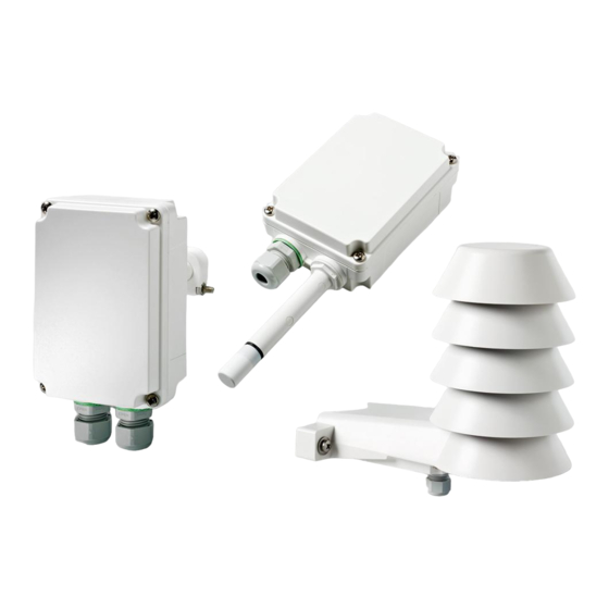
- Page 1 M211726EN-D User Guide Vaisala Humidity and Temperature Transmitter Series HMDW110...
- Page 2 Vaisala Oyj Vanha Nurmijärventie 21, FI-01670 Vantaa, Finland P.O. Box 26, FI-00421 Helsinki, Finland +358 9 8949 1 Visit our Internet pages at www.vaisala.com. © Vaisala Oyj 2019 with the local rules and No part of this document may be...
-
Page 3: Table Of Contents
Wiring Both Current Loops With a Single Power Supply....25 3.5.2 HMDW110 Power Supply Requirements..........25 3.5.3 Wiring HMDW110 With RDP100 Remote Display Panel..... 26 Wiring Devices With Modbus Output............27 Modbus Communication................28 Vaisala Insight Software................29 Connecting to Insight Software..............30 Using Service Port With Terminal Application .........31... - Page 4 HMDW110 User Guide M211726EN-D Serial Line Output and Communication............39 6.6.1 Measurement Output................39 6.6.2 Measurement Output Format..............41 6.6.3 Serial Line Communication..............43 Analog Output....................46 Calibration and Adjustment Commands............. 48 Other Commands................... 52 Maintenance....................54 Cleaning......................54 Calibration and Adjustment................54 7.2.1 Adjustment Types................... 55 7.2.2...
- Page 5 Table of Contents Recycling......................87...
- Page 6 Figure 9 HMDW110 Wiring With Single Power Supply........... 25 Figure 10 HMDW110 Supply Voltage Operating Region.......... 25 Figure 11 HMDW110 Wiring With RDP100 Remote Display Panel......26 Figure 12 HMDW110 Wiring, Modbus Output..............27 Figure 13 PuTTY Terminal Application................32 Figure 14 HMS110/112 Dimensions..................
- Page 7 List of Tables List of Tables Table Document Versions (English)................7 Table 2 Related Manuals....................7 Table 3 HMDW110 Series Output Parameters............9 Table 4 Default Modbus Serial Communication Settings........28 Table 5 HMDW110 Serial Commands................34 Table 6 ? Command......................35 Table 7 Errs Command....................36...
- Page 8 HMDW110 User Guide M211726EN-D Table 46 Mechanical Specifications................74 Table 47 Inputs and Outputs...................74 Table 48 Spare Parts and Accessories................76 Table 49 Default Modbus Serial Communication Settings........78 Table 50 Modbus Function Codes................. 78 Table 51 Modbus Measurement Data Registers (Read-Only)....... 79 Table 52 Modbus Status Registers (Read-Only)............80...
-
Page 9: About This Document
Chapter 1 – About This Document 1. About This Document 1.1 Version Information This document provides information for installing, operating, and maintaining HMDW110 series transmitters. Table 1 Document Versions (English) Document Code Description M211726EN-D January 2019. This document. Added information about transmitters with Modbus protocol. -
Page 10: Trademarks
Lists tools needed to perform the task. Indicates that you need to take some notes during the task. 1.4 Trademarks Vaisalaâ and HUMICAPâ are registered trademarks of Vaisala Oyj. Windowsâ is either a registered trademark or trademark of Microsoft Corporation in the United States and other countries. -
Page 11: Product Overview
When used as loop powered current output transmitters, HMDW110 series transmitters can be connected to Vaisala Remote Display Panel RDP100 for real-time viewing of the measurements. HMDW110 series can also supply the operating power to the display using only the loop power from the outputs. -
Page 12: Hmd110/112 Parts
HMDW110 User Guide M211726EN-D Parameter Symbol Units Description Enthalpy kJ/kg Sum of the internal energy of a thermodynamic system. BTU/lb Wet bulb °C The minimum temperature that can be reached by temperature evaporative cooling in the current conditions. °F Check the type label on your transmitter to verify its output parameters and scaling of the output channels. -
Page 13: Hmw110/112 Parts
Chapter 2 – Product Overview 2.4 HMW110/112 Parts Figure 2 HMW110/112 Parts Screw holes for mounting (2 pcs) Cable gland for 4 ... 8 mm diameter cable Sensors for humidity and temperature Porous PTFE filter (DRW239993SP) Type label Component board Probe Transmitter cover with captive screws More Information ‣... -
Page 14: Hms110/112 Parts
HMDW110 User Guide M211726EN-D 2.5 HMS110/112 Parts Figure 3 HMS110/112 Parts... -
Page 15: Component Board
Cable gland. Suitable for 4 ... 8 mm diameter cable. 2.6 Component Board All HMDW110 transmitter models use the same component board, which has 2 output types: Modbus mode (RS-485) and analog mode (current output). The output type is selected when ordering the device. -
Page 16: Analog Output Overrange Behavior
Analog Output (page 46). 2.8 Safety The Vaisala HMDW110 series transmitter delivered to you has been tested for safety and approved as shipped from the factory. Note the following precautions: CAUTION! Do not modify the unit or use it in ways not described in the documentation. -
Page 17: Regulatory Compliances
ESD-sensitive components. • Hold component boards by the edges and avoid touching component contacts. 2.9 Regulatory Compliances The Vaisala HMDW110 series is in conformity with the following directives: • RoHS-Directive • EMC-Directive Conformity is shown by compliance with the following standards: •... -
Page 18: Installation
HMDW110 User Guide M211726EN-D 3. Installation 3.1 Selecting Location When mounting duct model transmitters: • Avoid installing in a location where condensation may fall on the sensor inside the duct. • Position the sensor in the center of the duct. • Select a site where the transmitter can be installed horizontally, onto the side of the duct. -
Page 19: Figure 5 Hmd110/112 Installation
Chapter 3 – Installation Ø ≥13 Figure 5 HMD110/112 Installation 1. Remove the yellow transport protection cap and separate the fastening flange from the transmitter. 2. Use the flange to mark the location and size of the installation holes on the side of the duct. -
Page 20: Hmw110/112 Installation
HMDW110 User Guide M211726EN-D 5. Secure the transmitter to the flange by tightening the screw on the flange that holds the probe in place. 6. Open the transmitter cover, and route the cables through the cable glands. Connect the wires to the screw terminals according to the wiring instructions. -
Page 21: Figure 7 Hmw110/112 Installation
Chapter 3 – Installation ≥ 10 mm 88 mm ≤ 8 mm ≤ 3.5 mm Ø 4 ... 8 mm Figure 7 HMW110/112 Installation 1. Open the transmitter cover and use two screws (not included) to attach the transmitter to the wall. The probe and cable gland should point down. 2. -
Page 22: Hms110/112 Installation
HMDW110 User Guide M211726EN-D 3.4 HMS110/112 Installation • Medium size crosshead screwdriver (Pozidriv) • Small slotted screwdriver for screw terminals • Tools for cutting and stripping wires • 19 mm open-end wrench for tightening the cable gland Additional tools for pole installation: •... - Page 23 Chapter 3 – Installation 3. Adjust the length of cable between the cable gland and the terminal blocks. Make the cable short enough to close the cover without leaving a cable loop in the transmitter. 4. Disconnect the wired screw terminal blocks by pulling them off from the component board.
- Page 24 HMDW110 User Guide M211726EN-D 5. Mount the transmitter according to the type of the installation site: • Pole installation 1. Use the supplied clamp and screws to mount the transmitter on a pole. 2. To prevent the transmitter from turning on the pole, tighten the set screw on the center hole of the clamp.
- Page 25 Chapter 3 – Installation 3. Mount the transmitter using two screws of sufficient length. 100 mm Ø 5.5 mm...
-
Page 26: Wiring Devices With Analog Output
3.5 Wiring Devices With Analog Output With HMDW110 transmitters ordered with analog output, you must always connect the humidity measurement current loop (HUM, terminals 5 and 6) to power the transmitter. Connecting the temperature measurement current loop (terminals 7 and 8) is optional. -
Page 27: Wiring Both Current Loops With A Single Power Supply
Figure 9 HMDW110 Wiring With Single Power Supply 3.5.2 HMDW110 Power Supply Requirements HMDW110 series transmitters are designed for a supply voltage range of 10 ... 28 VDC. The minimum required voltage depends on the loop resistance (0 ... 600 Ω) as shown below. -
Page 28: Wiring Hmdw110 With Rdp100 Remote Display Panel
Connecting the temperature measurement current loop (terminals 7 and 8) is optional. Connect the RDP100 remote display panel using terminals 1 ... 4. The HMDW110 series transmitter provides both power and data to the RDP100. Terminals 1 ... 4 shall be used only for connecting the RDP100 (optional) when using the analog outputs. -
Page 29: Wiring Devices With Modbus Output
Chapter 3 – Installation When using the RDP100 with HMDW110 series transmitters, do not connect the Extpwr jumper to the RDP100 component board. 3.6 Wiring Devices With Modbus Output Use terminals 1 ... 4 for supply power and Modbus output. In addition to RS-485 data wires, the common wire (ground reference) must be connected between the RS-485 host and the HMDW110 transmitter. -
Page 30: Modbus Communication
19200 Parity Number of data bits Number of stop bits Modbus device address Serial delay Communication mode Modbus RTU Use Vaisala Insight software to change the Modbus serial communication settings if needed. More Information ‣ Vaisala Insight Software (page 29) -
Page 31: Vaisala Insight Software
Chapter 5 – Vaisala Insight Software 5. Vaisala Insight Software Vaisala Insight PC software can be used to check, configure, and adjust HMDW110 series transmitters intuitively without typing any serial commands. The transmitter can be connected to Vaisala Insight software using a Vaisala USB cable for computer connection (219690). -
Page 32: Connecting To Insight Software
3. Connect the USB cable to the service port of the transmitter. 4. Wait for Insight software to detect the transmitter. If the transmitter is not detected, disconnect and reconnect the Vaisala USB cable to the service port connector of the transmitter. -
Page 33: Using Service Port With Terminal Application
RDP100 remote display panel from interfering with your connection. 6.2 Terminal Application Settings You need a terminal application to be able to use the service port commands of the HMDW110 series transmitter. You can download the PuTTY terminal application from http:// www.vaisala.com/en/search/download... -
Page 34: Figure 13 Putty Terminal Application
• Eight data bits • One stop bit • Number of the virtual COM port that has been created for your cable by the Vaisala USB driver. You can check which port the USB cable is using with the Vaisala USB Device Finder application that has been installed in the Windows Start menu. -
Page 35: Accessing Service Port Command Interface In Devices With Modbus Output
Follow the steps below to connect to the serial line with a transmitter with Modbus output. You can also use the procedure to retrieve the communication settings of your device, if you do not know them. You must use the Vaisala USB cable (Vaisala order code: 219690) for the connection. -
Page 36: Table 5 Hmdw110 Serial Commands
HMDW110 User Guide M211726EN-D Table 5 HMDW110 Serial Commands Command Description Device Information and Status Show device information. Show device information (will respond in poll mode). errs Show active errors. help Show list of serial commands. system Show firmware information. time Show transmitter uptime (time since last reset). -
Page 37: Device Information And Status
Chapter 6 – Using Service Port With Terminal Application Command Description ctclr Clear user calibration for temperature measurement. Factory calibration remains. ctext Show or set adjustment information text. fcrh Two-point calibration after humidity sensor change. Show adjustment offset and gain. Set adjustment offset and gain. -
Page 38: Table 7 Errs Command
HMDW110 User Guide M211726EN-D Syntax Description Example: HMDW110 / 1.0.6 Serial number : H0134007 Batch number : H0130002 Sensor number : H0090003 Sensor model : Humicap 180R Order code : HMD1102A1VA1 Cal. date : 20140619 Cal. info : VAISALA/HEL Time... -
Page 39: Table 9 Help Command
Chapter 6 – Using Service Port With Terminal Application ERRS Command Response Corresponding Error Ambient temperature error Ambient temperature out of range. [48] Program flash check sum error Firmware checksum mismatch. [49] Parameter flash check sum error Device settings corrupted. [50] INFOA check sum error Additional configuration settings corrupted. -
Page 40: Table 10 System Command
HMDW110 User Guide M211726EN-D Syntax Description Example: help ADDR AERR AMODE AOVER ASEL ATEST CDATE CLOSE CRHCLR CTCLR CTEXT ERRS FCRH FILT FORM FRESTORE HELP INTV OPEN RESET SDELAY SEND SERI SMODE SYSTEM TIME UNIT Table 10 System Command Syntax Description system<cr>... -
Page 41: Serial Line Output And Communication
Chapter 6 – Using Service Port With Terminal Application Syntax Description Example: system Device Name : HMDW110 Copyright : Copyright (c) Vaisala Oyj 2017. All rights reserved. SW Name : HMP113 SW date : 2018-01-03 SW version : 2.2.3 HMDW HW version Table 11 Time Command... -
Page 42: Table 13 R Command
HMDW110 User Guide M211726EN-D Table 13 R Command Syntax Description r<cr> Start the continuous outputting of measurement values as an ASCII text string to the serial line. Example (measurement message in default format): T= 22.8 'C RH= 39.5 %RH Td= 8.3 'C Tw= 14.5 'C h= 40.4 kJ/kg T= 22.8 'C RH= 39.5 %RH Td= 8.3 'C Tw= 14.5 'C h= 40.4 kJ/kg... -
Page 43: Measurement Output Format
Chapter 6 – Using Service Port With Terminal Application Syntax Description Example: intv 5 s Output interval: 5 S 6.6.2 Measurement Output Format Table 16 Unit Command Syntax Description unit<cr> Show current setting of the unit command. unit [m|n]<cr> Set types of units used on the serial line. m = metric units, for example, Celsius n = non-metric units, for example, Fahrenheit Example (set units to non-metric):... -
Page 44: Table 18 Output Parameters For Form Command
HMDW110 User Guide M211726EN-D Syntax Description Example: set output format as RH and T, with start of text (ASCII character 002) and end of text (003) ASCII codes, and without line feed and carriage return at the end: form #002 3.1 "RH=" RH U4 3.1 "T=" T " " U3 #003... -
Page 45: Serial Line Communication
Open a connection to a device at the specified address. Required when device is in poll mode. Address range 0 ... 255. Example: open 5 HMDW110 5 line opened for operator commands Table 21 Close Command Syntax Description close<cr> Close the connection that was opened with the open command. -
Page 46: Table 23 Seri Command
HMDW110 User Guide M211726EN-D Syntax Description Example (shows 0 as current address, enter 5 as the new address): addr Address : 0 ? 5 Table 23 Seri Command Syntax Description seri<cr> Show current serial line settings. seri [baud p d s]<cr>... -
Page 47: Table 25 Smode Command
Chapter 6 – Using Service Port With Terminal Application Syntax Description Example (set serial line delay to 200 milliseconds): sdelay 50 Serial delay : 50 Table 25 Smode Command Syntax Description smode<cr> Show current start-up operating mode of the serial line, and prompt to enter new mode. New mode is taken into use when the device is reset or powered up. -
Page 48: Analog Output
HMDW110 User Guide M211726EN-D 6.7 Analog Output Table 26 Aerr Command Syntax Description aerr ?<cr> Show currently set analog output error level for both channels. aerr<cr> Show currently set analog output error levels, prompt to enter new values. aerr [ch1] [ch2]<cr> Set error level for both channels without prompting. -
Page 49: Table 29 Asel Command
Chapter 6 – Using Service Port With Terminal Application Syntax Description Example (enable 10 % overrange for analog outputs): aover on AOVER : ON Table 29 Asel Command Syntax Description asel ?<cr> Show currently set analog output parameters and scaling. asel<cr> Show currently set analog output parameters and scaling, prompt to enter new scaling values. -
Page 50: Calibration And Adjustment Commands
HMDW110 User Guide M211726EN-D 6.8 Calibration and Adjustment Commands CAUTION! Before using the calibration and adjustment commands, read through Calibration and Adjustment (page 54). Table 30 Cdate Command Syntax Description cdate<cr> Show currently stored calibration date. cdate [yyyymmdd]<cr> Set a new calibration date. -
Page 51: Table 32 Crhclr Command
Chapter 6 – Using Service Port With Terminal Application Table 32 Crhclr Command Syntax Description crhclr<cr> Clear the current user adjustment for humidity. Factory calibration remains. Example: crhclr Table 33 Ct Command Syntax Description ct<cr> Start the two-point temperature calibration and adjustment sequence. For a full adjustment procedure, see Two-Point Temperature Calibration and Adjustment Using Computer... -
Page 52: Table 35 Ctext Command
HMDW110 User Guide M211726EN-D Table 35 Ctext Command Syntax Description ctext<cr> Show currently stored calibration text. ctext [sss]<cr> Set a new calibration text. sss = Text string, maximum length 24 characters. Example (set calibration text to Lab1/John): ctext Lab1/John Cal. info : Lab1/John Table 36 Fcrh Command... -
Page 53: Table 38 Li Command
Chapter 6 – Using Service Port With Terminal Application Syntax Description Example (shows default state without user adjustments - offset is 0 and gain is 1 for both humidity (Cp offset and gain) and temperature): Cp offset : 0.00000000E+00 Cp gain : 1.00000000E+00 T offset : 0.00000000E+00 T gain : 1.00000000E+00 Table 38 Li Command... -
Page 54: Other Commands
HMDW110 User Guide M211726EN-D 6.9 Other Commands Table 39 Filt Command Syntax Description filt [f.fff]<cr> Set the speed at which the latest measurement result is integrated into the humidity and temperature readings. The command affects both analog output and serial line output. -
Page 55: Table 41 Reset Command
Chapter 6 – Using Service Port With Terminal Application Table 41 Reset Command Syntax Description reset<cr> Resets the device. Example: reset HMDW110 / 2.2.3... -
Page 56: Maintenance
HMDW110 series transmitters are fully calibrated as shipped from the factory. You can use the service port to calibrate and adjust the humidity and temperature measurement of the transmitter as needed. -
Page 57: Adjustment Types
Chapter 7 – Maintenance 7.2.1 Adjustment Types You can perform a one-point calibration and adjustment with Vaisala handheld meters that utilize the MI70 measurement indicator (for example, HM70). Connecting to the service port using a computer and a terminal program allows you to perform calibration and adjustment tasks using serial commands. -
Page 58: Calibration And Adjustment Using Handheld Meter And Reference Probe
• Connection cable for HM70 handheld meter (219980SP) • Medium size cross-head screwdriver (Pozidriv). 1. Insert the reference probe in the same environment as the probe of the HMDW110 series transmitter. You can also perform this procedure in the ambient environment, as long as it is reasonably stable. - Page 59 HMDW110 series transmitter and the reference probe. Depending on the result, proceed as follows: • If the HMDW110 series transmitter is within its accuracy specification, there is no need to proceed with the adjustment. Select Back > Exit to leave the adjustment mode.
-
Page 60: One-Point Humidity Calibration And Adjustment Using Handheld Meter And Hmk15 Humidity Calibrator
RDP100 remote display panel from interfering with your connection. 2. Plug in the connection cable 219980SP to the service port of the HMDW110 series transmitter, and the other end to port I of the MI70 indicator. If any other probes are connected to the MI70, disconnect them. -
Page 61: Two-Point Humidity Calibration And Adjustment Using Computer And Hmk15 Humidity Calibrator
• Driver for Vaisala USB cable installed • Vaisala USB cable for computer connection (219690) • Vaisala HMK15 Humidity Calibrator with LiCl (11 %RH) and NaCl (75 %RH) salt solutions prepared. Other solutions may be used, but the difference between the two points must be ≥... - Page 62 RDP100 remote display panel from interfering with your connection. 2. Plug in connection cable 219690 to the service port of the HMDW110 series transmitter, and the other end to a free USB port on your computer.
- Page 63 Chapter 7 – Maintenance 9. Give the crh command to start the calibration and adjustment sequence. The transmitter shows the measured RH value and prompts you to enter the real humidity of the first reference point. RH : 11.5378 1. ref ? 10.
-
Page 64: Two-Point Temperature Calibration And Adjustment Using Computer
18. Disconnect the connection cable from the service port. 19. Reconnect the terminal blocks and close the cover. 7.6 Two-Point Temperature Calibration and Adjustment Using Computer You can also use Vaisala Insight software for performing calibration and adjustment. See Vaisala Insight Software (page 29). - Page 65 RDP100 remote display panel from interfering with your connection. 2. Plug in connection cable 219690 to the service port of the HMDW110 series transmitter, and the other end to a free USB port on your computer.
- Page 66 HMDW110 User Guide M211726EN-D 8. Give the ct command to start the calibration and adjustment sequence. The transmitter shows the measured T value and prompts you to enter the real temperature of the first reference point. T : 22.9424 1. ref ? 9.
-
Page 67: Replacing Humicap Sensor On Hmd110/112 And Hmw110/112
Chapter 7 – Maintenance 15. Update the calibration date and calibration information on the transmitter using the cdate and ctext commands. Example: Set calibration date to 2018-07-04 and calibration info text to "Lab2/Mike". cdate 20180704 Cal. date : 20180704 ctext Lab2/Mike Cal. - Page 68 HMDW110 User Guide M211726EN-D 3. Remove the filter to access the sensors. Vaisala HUMICAPâ sensor. Handle by the plastic frame. Temperature sensor. Do not touch or attempt to remove. Sensor socket. Transmitter probe. 4. Pull out the old HUMICAPâ sensor, and insert the new one.
-
Page 69: Replacing Humicap Sensor On Hms110/112
Chapter 7 – Maintenance 7.8 Replacing HUMICAP Sensor on HMS110/112 • New HUMICAPâ humidity sensor (HUMICAP180R or HUMICAP180V) • New filter (always recommended when replacing the sensor) • Medium size crosshead screwdriver (Pozidriv) • Flat-head screwdriver • 3 mm hex key (Allen key) for opening the radiation shield screws You will need to remove the radiation shield to access the sensor, and this is difficult to do while the transmitter remains mounted on a pole or wall. -
Page 70: Filter Selection
When replacing the filter, note that there are two alternative filter options depending on the probe model: • HMS and HMD products use the membrane filter (Vaisala order code ASM210856SP) • HMW products use the porous PTFE filter (Vaisala order code DRW239993SP) -
Page 71: Troubleshooting
If you experience problems when using the transmitter, check the following table before contacting Vaisala. If the problem you have is not listed in the table, or if the proposed solution does not fix the problem, contact a Vaisala Service Center. For contact information, see Technical Support (page 87). -
Page 72: Error Messages In Insight Software
Temperature Temperature sensor is Check that the legs of the temperature sensor measurement error. short circuited, are not short circuited. Contact a Vaisala Service [44] damaged, or missing. Center if the temperature sensor is damaged. Humidity Humidity sensor is wet. Wait for the humidity sensor to dry, or remove measurement error. -
Page 73: Error Codes In Mi70 Handheld Meter
[57] Calibration certificate checksum mismatch. [58] In case of constant error, contact a Vaisala Service Center. More Information ‣ Technical Support (page 87) 8.3 Error Codes in MI70 Handheld Meter If several errors are active at the same time, the MI70 shows the sum of currently active error codes. -
Page 74: Unknown Serial Settings
You can check the current serial settings of your transmitter by connecting to the serial line, or with Vaisala Insight software. More Information ‣ Vaisala Insight Software (page 29) ‣ Accessing Service Port Command Interface in Devices With Modbus Output (page 33) -
Page 75: Technical Data
-40 ... -20 °C (-40 ... -4 °F) 0 ... 100 %RH ±4 %RH Stability in typical HVAC applications ±0.5 %RH/year Humidity sensor Vaisala HUMICAPâ 180R Temperature Measurement range -40 ... +60 °C (-40 ... +140 °F) Accuracy at +20 °C (+68 °F) ±0.2 °C (±0.36 °F) Temperature dependence ±0.01 °C/°C... -
Page 76: Table 45 Operating Environment (All Models)
HMDW110 User Guide M211726EN-D Parameter Description/Value Wet bulb temperature ±0.5 °C (0.9 °F) Enthalpy ±1.6 kJ/kg (0.7 BTU/lb) Factory calibration uncertainty at 20 °C (+68 °F) ±1.5 %RH/±0.2 °C Table 45 Operating Environment (All Models) Property Description/Value Operating temperature -40 ... +60 °C (-40 ... +140 °F) Operating humidity 0 ... -
Page 77: Dimensions
Chapter 9 – Technical Data 9.1 Dimensions Ø5.5 Ø4...8 121.5 264.2 Figure 14 HMS110/112 Dimensions 290.8 40.6 250.2 244.5 Ø12 Ø3.5 Ø12 Ø4...8 Ø4...8 Figure 15 HMD110/112 Dimensions... -
Page 78: Spare Parts And Accessories
HMDW110 User Guide M211726EN-D 40.6 Ø10 Ø3.5 Ø3.5 Ø10 Ø12 Ø4...8 Figure 16 HMW110/112 Dimensions 9.2 Spare Parts and Accessories Table 48 Spare Parts and Accessories Item Order Code Remote Display Panel RDP100 Conduit fitting + O-ring (M16x1.5 / NPT1/2 Inch) 210675SP Conduit fitting + O-ring (M16x1.5 / PG9, RE-MS) - Page 79 Chapter 9 – Technical Data Item Order Code HUMICAPâ 180R sensor HUMICAP180R Catalytic HUMICAPâ sensor HUMICAP180V...
-
Page 80: Appendix A: Modbus Reference
HMDW110 User Guide M211726EN-D Appendix A. Modbus Reference A.1 Default Communication Settings The following table lists the default Modbus serial settings of devices ordered with the Modbus configuration option. Table 49 Default Modbus Serial Communication Settings Description Default Value Serial bit rate 19200... -
Page 81: Modbus Registers
Appendix A – Modbus Reference Despite the specification, some Modbus masters may expect "big-endian" word order (most significant word first). In such case, you must select "word-swapped" floating point format in your Modbus master for the Modbus registers of the device. Reading the measurement data registers with incorrect floating point format setting may occasionally result in correct-looking values. -
Page 82: Status Registers
HMDW110 User Guide M211726EN-D A.4.2 Status Registers Table 52 Modbus Status Registers (Read-Only) Register Address Register Description Data Notes Number (Hexadecimal) Format (Decimal) 0200 Device status 16-bit 1 = No errors integer 0203 Error code 32-bit field 0205 Security hash 32-bit Security hash changes on... -
Page 83: Configuration Registers
Appendix A – Modbus Reference A.4.3 Configuration Registers Table 54 Modbus Configuration Data Registers (Writable) Register Address Register Description Data Unit / Valid Range Number (Hexadecimal) Format (Decimal) Filtering 0310 Filtering factor 32-bit float 0.001 (maximum filtering) ... 1.000 (no filtering) Communication 1537 0600 Modbus address... -
Page 84: Test Value Registers
HMDW110 User Guide M211726EN-D A.4.4 Test Value Registers Read the known test values from the test registers to verify the functionality of your Modbus implementation. Table 55 Modbus Test Registers (Read-Only) Register Address Register Description Data Test Value Number (Hexadecimal) Format (Decimal) -
Page 85: Modbus Communication Examples
Appendix A – Modbus Reference A.5 Modbus Communication Examples Reading Relative Humidity Value Device address used in the following examples is 240 (F0 The values returned by the device differ depending on the ambient conditions and/or device settings. Your device might not return exactly same values. Request Response Bytes on the Line... - Page 86 HMDW110 User Guide M211726EN-D Writing Filtering Factor Value Request Response Bytes on the Line Description Bytes on the Line Description (Hexadecimal) (Hexadecimal) (silence for 3.5 bytes) Start of Modbus RTU (silence for 3.5 bytes) Start of Modbus RTU frame frame...
- Page 87 Appendix A – Modbus Reference...
- Page 88 HMDW110 User Guide M211726EN-D...
-
Page 89: Warranty
Please see the applicable supply contract or Conditions of Sale for details of the warranty for each product. Technical Support Contact Vaisala technical support at helpdesk@vaisala.com. Provide at least the following supporting information: • Product name, model, and serial number •... - Page 90 HMDW110 User Guide M211726EN-D...
- Page 92 www. v aisala.com...